Rotary Position Control System for Hydraulic Cylinder Project

Verified

Added on  2022/01/03

|15
|1198
|18
Project
AI Summary
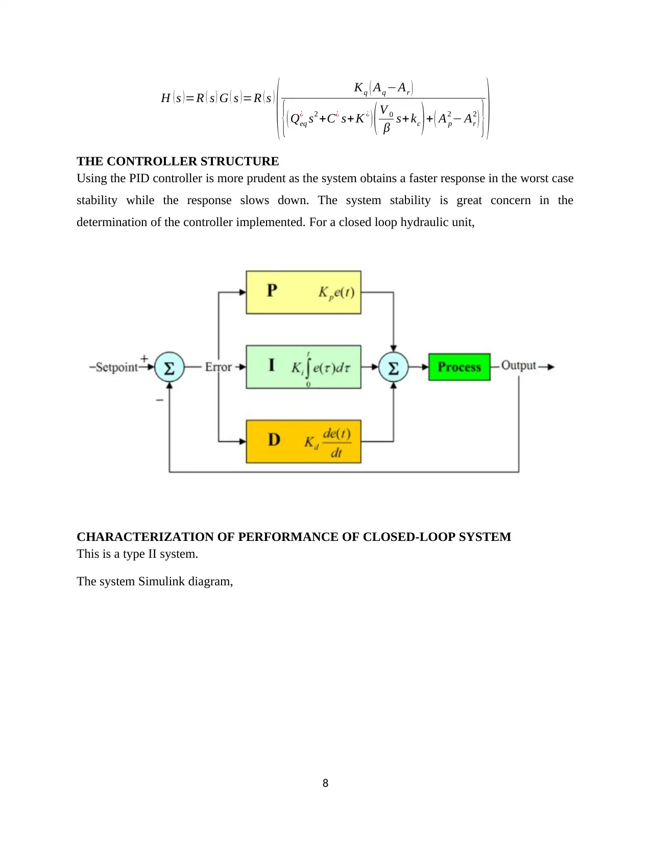
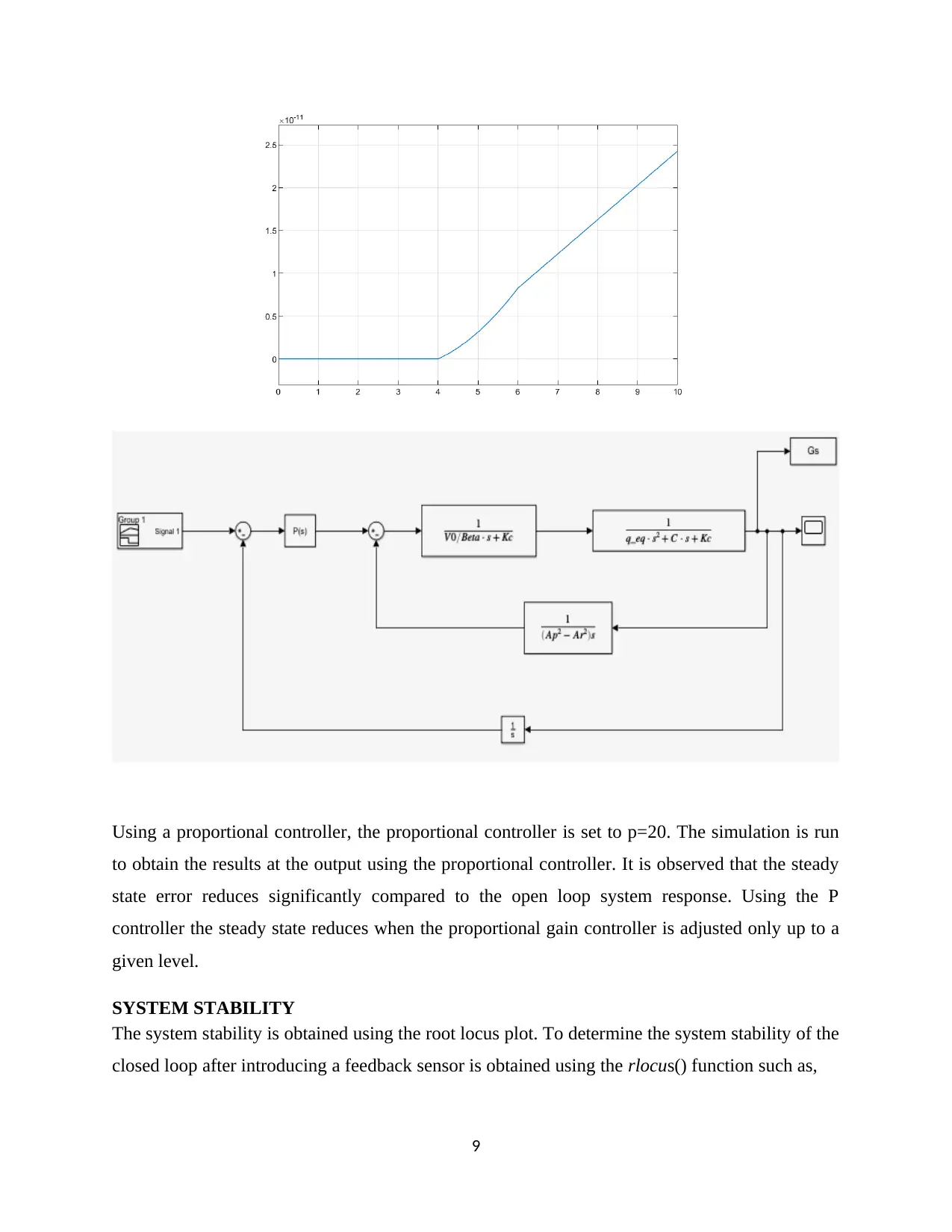
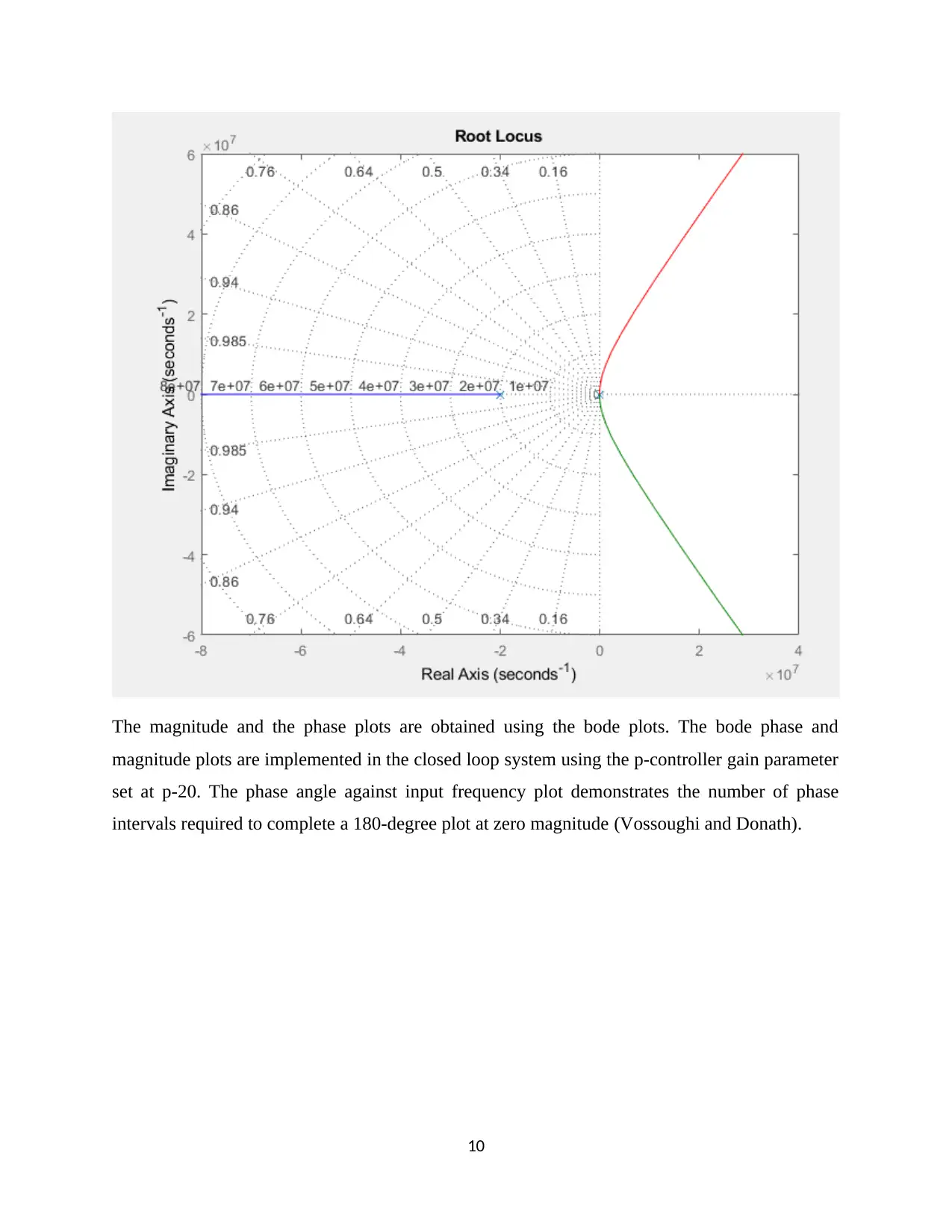
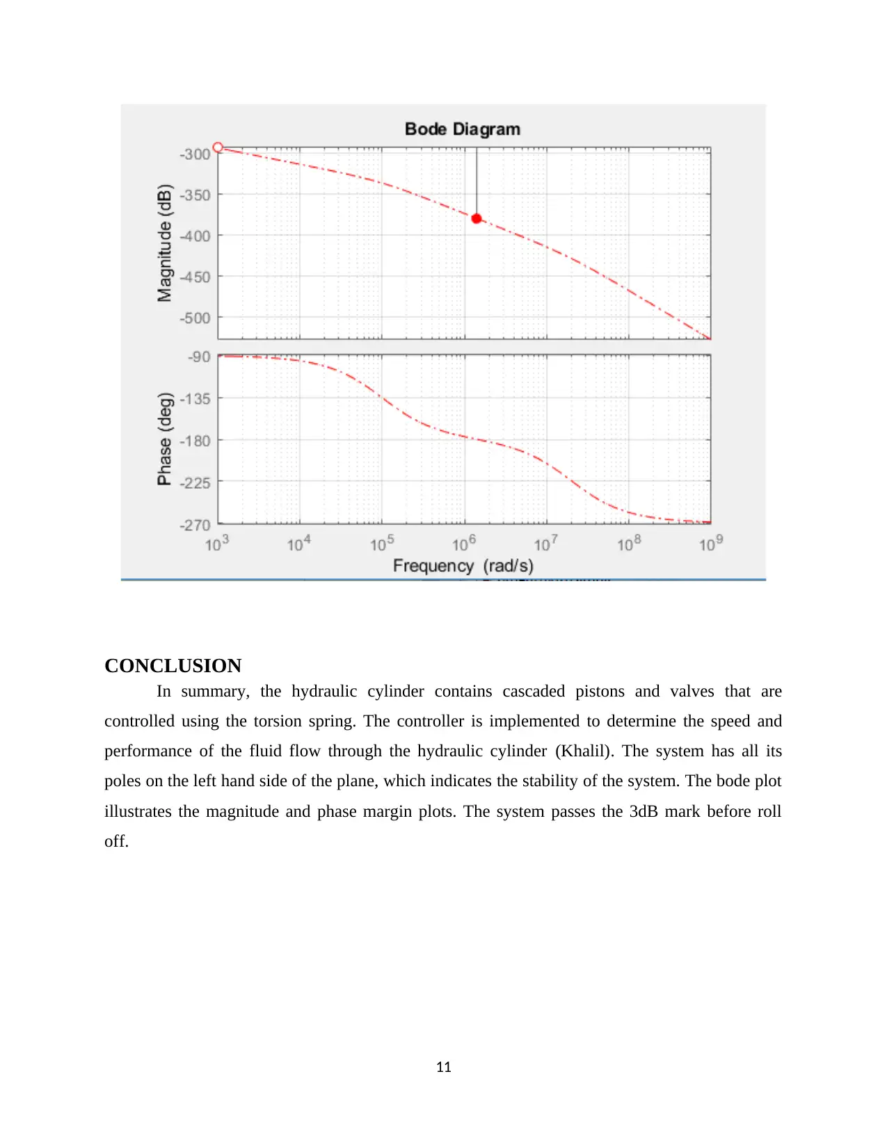
This project analyzes a hydraulic cylinder control system, focusing on its rotary position control with a torsion spring. The assignment begins with an introduction to hydraulic systems and their applications, followed by a detailed explanation of system parameters and dynamic modeling. The core of the project involves developing a block diagram and transfer function to represent the system's behavior. The student then explores the design and implementation of a PID controller to enhance system performance, discussing the characterization of the closed-loop system. System stability is evaluated using root locus and Bode plots, providing insights into the system's response. The project concludes with a summary of findings and a reference list. The appendix includes MATLAB code for simulations and analysis, demonstrating the practical application of the theoretical concepts discussed.
Document Page
Control System
Hydraulic Cylinder:
Rotary Position System with Torsion Spring
Student Name
Student ID Number
Instructor
Institutional Affiliation
Date of Submission
tabler-icon-diamond-filled.svg

Paraphrase This Document

Need a fresh take? Get an instant paraphrase of this document with our AI Paraphraser
Document Page
TABLE OF CONTENTS
INTRODUCTION...........................................................................................................................2
SYSTEM PARAMETERS..............................................................................................................2
DYNAMIC MODELING............................................................................................................2
BLOCK DIAGRAM SHOWING THE DYNAMICS OF THE CLOSED LOOP SYSTEM
AND THE CONTROLLER.........................................................................................................6
TRANSFER FUNCTION............................................................................................................7
THE CONTROLLER STRUCTURE..........................................................................................8
CHARACTERIZATION OF PERFORMANCE OF CLOSED-LOOP SYSTEM.....................8
SYSTEM STABILITY................................................................................................................9
CONCLUSION..............................................................................................................................11
REFERENCES..............................................................................................................................12
APPENDIX....................................................................................................................................13
1
Document Page
INTRODUCTION
The hydraulic systems are implemented in the actuation technology for systems that
require the substantial power amplification. Hydraulic actuators are used in large cranes to full
motion bases for aircraft flight control simulators (Chase, Li and Li). The hydraulic actuator acts
as a position control system and a rotary inertial load is attached to the output of the system.
SYSTEM PARAMETERS
Parameter Symbol Value
1. Hydraulic power
piston area
A 0.003 m2
2. Net hydraulic pressure
on piston
P N/m2
3. Inertia of load JL 10 N-m-sec2
4. Load damping
coefficient
BL 1.0N-m-sec
DYNAMIC MODELING
For rotary motion, the work done is given as a function of torque,
W = τdθ
P= dW
dt
P=τω
2
Document Page
The moment of inertia for the hydraulic piston is given as,
Ji=M L2=r2 dm Ldistance ¿ point ¿ axisof rotation
To determine the rotational stiffness where the hydraulic cylinder pistons are associated with
torsional spring on a shaft (Zahe and Backe),
τ =K θ
In the case scenario, the hydraulic cylinder is connected to the torsional spring. For the two
bodies to rotate about the same axis, the torque exerted by one element on another is
accompanied by a reaction torque of equal magnitude and opposite direction (Rannow and Tu).
The D’Alembert’s law is implemented such that,
Ji ¨θ+b ˙θ+ =τ
T =J i ¨θ
Figure 1 Bolton, Mechatronics PowerPoint, 4th Edition [Pearson Education Limited, 2008]
I ( d2 θ
d t2 )+ c
dt +=T
The fluid system and the hydraulic system for the piston,
F=P1 AP2 Ab ˙x=m ¨x
3
tabler-icon-diamond-filled.svg

Paraphrase This Document

Need a fresh take? Get an instant paraphrase of this document with our AI Paraphraser
Document Page
Considering the hydraulic fluid in the piston area is greater than that of steel, the bulk modulus is
obtained as,
β=V ( p
V )= p ( p
V ) 2109 N /m2
The constitutive equation is given as,
rh=Qp= d
dt ( V 0 ρ )=V 0

dt
= ρ
β dp
Q= V 0
β
dp
dt ; V 0
β Cf
Q=Cf
dp
dt
m ˙x =f m
Cf ˙p1=Q1 ;Cf ˙p2 =Q2
Q1 x=Rx ps p1 lx
To obtain the hydraulic capacitance,
q1q2= dV
dt ; V = Ah
q1q2=A dh
dt
q1q2= A
pg
dp
dt
A
pg =C q1q2=C dp
dt
pA ( r ) kl QBl ˙QJ i ¨Q=0
Using the Lagrange’s equations of motion for a second order system,
4
Document Page
¿
[ ( x l1 cos ( β ) ) c1
0 +l1 sin β c2
0
x c1
0l2 cos β c1
0 +l2 sin β c2
0
x l2 cos β c1
0 +l2 sin β c2
0 ]
The equations of motion are resolved to
d
dt ( dT
d ˙q ) dT
dq + dV
dq =Qnc
T
( q2q1 ) ¨x +q2 l1 sin β ¨β+ m2 l1 cos β ˙β2=F1F2 sin (θ)
( J i+q2 l1
2 ) ¨β +q2 l1 ¨x sin β+q2 g l1 cos β=F2 l2 cos(β +θ)
The matrix representation is given as,
Q ( l ) ¨x + H ( q , ˙q ) =S ( l ) T
[ q1 +q2 q2 l1 sin( β )
q2 l1 sin ( β ) q2 l1
2 + Ji ] ¨x + [ q2 l1 cos β ¨β2
q2 g l1 cos β ] =
[ 1 sin (θ)
0 l2 cos (θ+ β ) ] [ F1
F2 ]
The flow equation shows the relationship between the pressure and the total flow of the bulk
cavity node method (Yao, Bu and Tu),
P= E0
V Qi dt
The flow equation of the rodless cavity,
d pw
dt = βe
V w 0 + Aw x ( Qhsv Qx Aw ˙x )
d p y
dt = βe
V y 0 + A y x ( Qx+ A y ˙xQout )
Qx=kc ( p y pw )
5
Document Page
BLOCK DIAGRAM SHOWING THE DYNAMICS OF THE CLOSED LOOP SYSTEM
AND THE CONTROLLER
The continuity flow for the cylinder
Linearizing the system,
qeq ¨x+ De ˙x+ Ke=Se F
Qp= A p ˙y + V 0
β
d P p
dt + A p
β
d P p
dt
Qr = Ar ˙y + V 0
β
d Pr
dt + Ar
β
d Pr
dt
6
tabler-icon-diamond-filled.svg

Paraphrase This Document

Need a fresh take? Get an instant paraphrase of this document with our AI Paraphraser
Document Page
Qp +Qr = ( Ap + Ar ) ˙y+ V 0
β ( d Pr
dt d Ppr
dt ) + y
β ( A p
d Pp
dt + Ar
d Pr
dt )
Qp +Qr = ( Ap + Ar ) ˙y+ V 0
β ( d Pp
dt d Ppr
dt )
d Pp
dt d Ppr
dt = ˙PL
Qp +Qr = ( Ap + Ar ) ˙y+ V o
β ( d P p
dt d Ppr
dt )
TRANSFER FUNCTION
A second order model can be obtained by linking the two sections, fluid system, and torsion
rotary system. There are two motions in the x and y directions. The y direction affects the piston
by closing the outlet when y is adjusted. Using the Laplace transform,
V o
β s PL ( s ) +K c PL ( s ) =Kq X ( s ) ( A p + Ar ) sY ( s )
The Laplace transform of the equation of motion are:
qeq s2 Y ( s ) =PL ( s ) ( Ap Ar )
The transfer function is given as,
G( s)= Y ( s )
X ( s )
PL ( s )= Kq X ( s )
V 0
β s +kc
Ap + Ar
V 0
β s+kc
sY ( s )
Considering the damping and the torsion stiffness in the hydraulic modeling,
G ( s )= Kq ( Aq Ar )
{( Qeq
¿ s2 +C¿ s+ K ¿ ) ( V 0
β s+ kc )+ ( Ap
2 Ar
2 ) }
For a closed loop, the transfer function is given as,
7
Document Page
H ( s ) =R ( s ) G ( s ) =R ( s )
( Kq ( Aq Ar )
{( Qeq
¿ s2 +C¿ s+K ¿
) ( V 0
β s+ kc ) + ( A p
2 Ar
2
) } )
THE CONTROLLER STRUCTURE
Using the PID controller is more prudent as the system obtains a faster response in the worst case
stability while the response slows down. The system stability is great concern in the
determination of the controller implemented. For a closed loop hydraulic unit,
CHARACTERIZATION OF PERFORMANCE OF CLOSED-LOOP SYSTEM
This is a type II system.
The system Simulink diagram,
8
Document Page
Using a proportional controller, the proportional controller is set to p=20. The simulation is run
to obtain the results at the output using the proportional controller. It is observed that the steady
state error reduces significantly compared to the open loop system response. Using the P
controller the steady state reduces when the proportional gain controller is adjusted only up to a
given level.
SYSTEM STABILITY
The system stability is obtained using the root locus plot. To determine the system stability of the
closed loop after introducing a feedback sensor is obtained using the rlocus() function such as,
9
tabler-icon-diamond-filled.svg

Paraphrase This Document

Need a fresh take? Get an instant paraphrase of this document with our AI Paraphraser
Document Page
The magnitude and the phase plots are obtained using the bode plots. The bode phase and
magnitude plots are implemented in the closed loop system using the p-controller gain parameter
set at p-20. The phase angle against input frequency plot demonstrates the number of phase
intervals required to complete a 180-degree plot at zero magnitude (Vossoughi and Donath).
10
Document Page
CONCLUSION
In summary, the hydraulic cylinder contains cascaded pistons and valves that are
controlled using the torsion spring. The controller is implemented to determine the speed and
performance of the fluid flow through the hydraulic cylinder (Khalil). The system has all its
poles on the left hand side of the plane, which indicates the stability of the system. The bode plot
illustrates the magnitude and phase margin plots. The system passes the 3dB mark before roll
off.
11
chevron_up_icon
1 out of 15
circle_padding
hide_on_mobile
zoom_out_icon
[object Object]