MET230L Hydraulic and Pneumatic Systems Lab: Unit 5 Project Part 3

Verified

Added on  2022/08/27

|9
|366
|14
Project
AI Summary
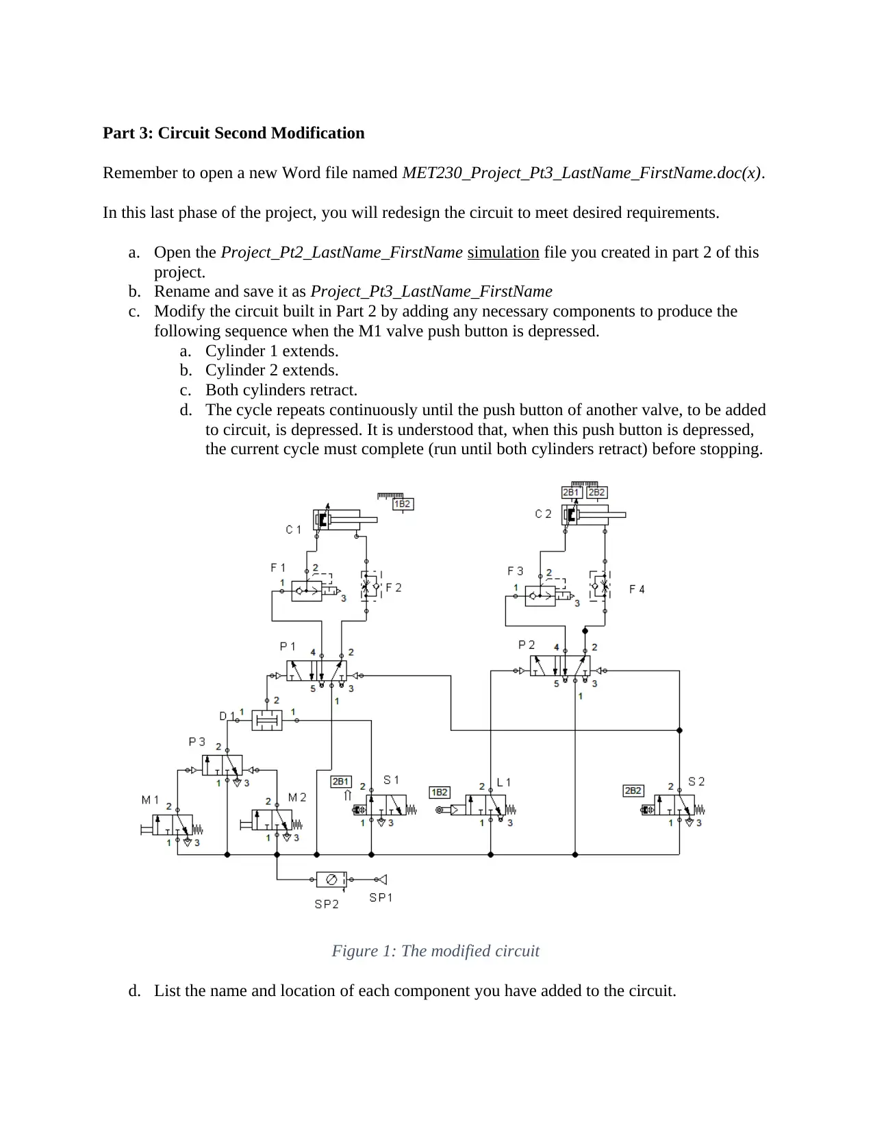
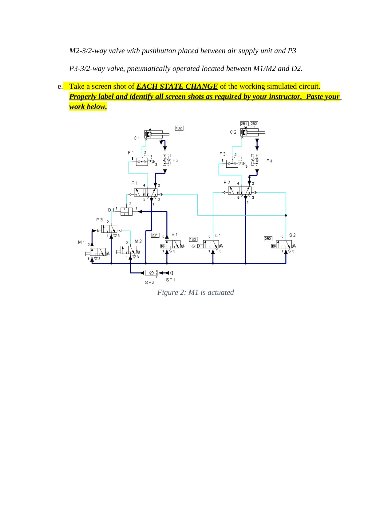
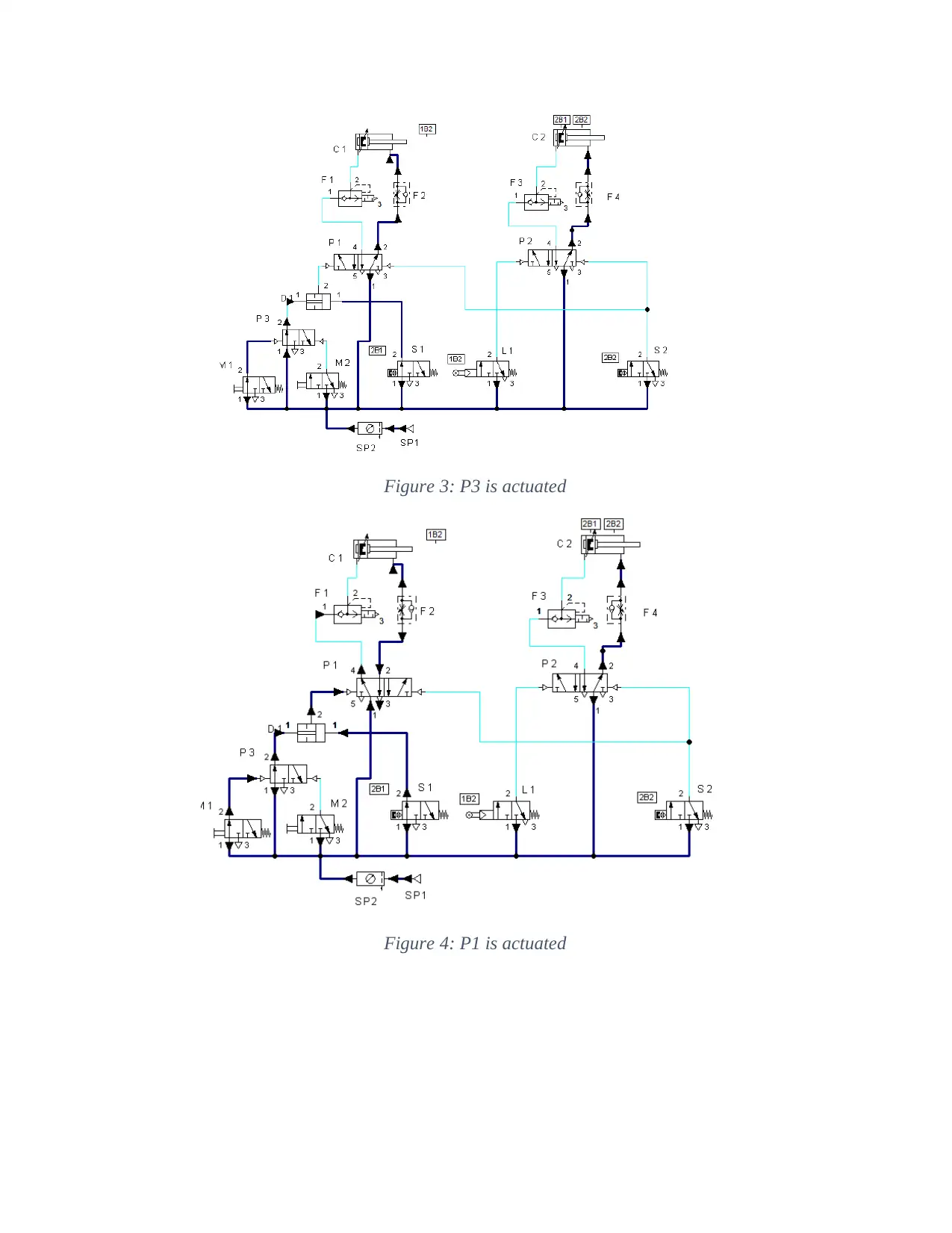
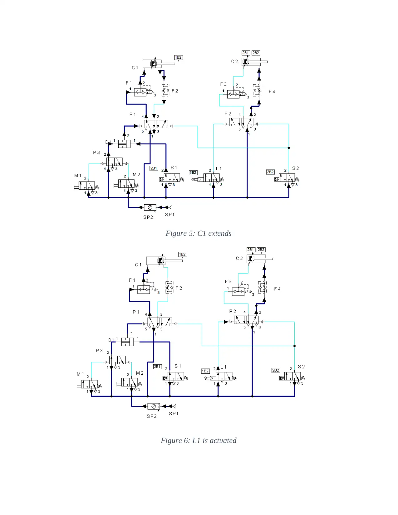
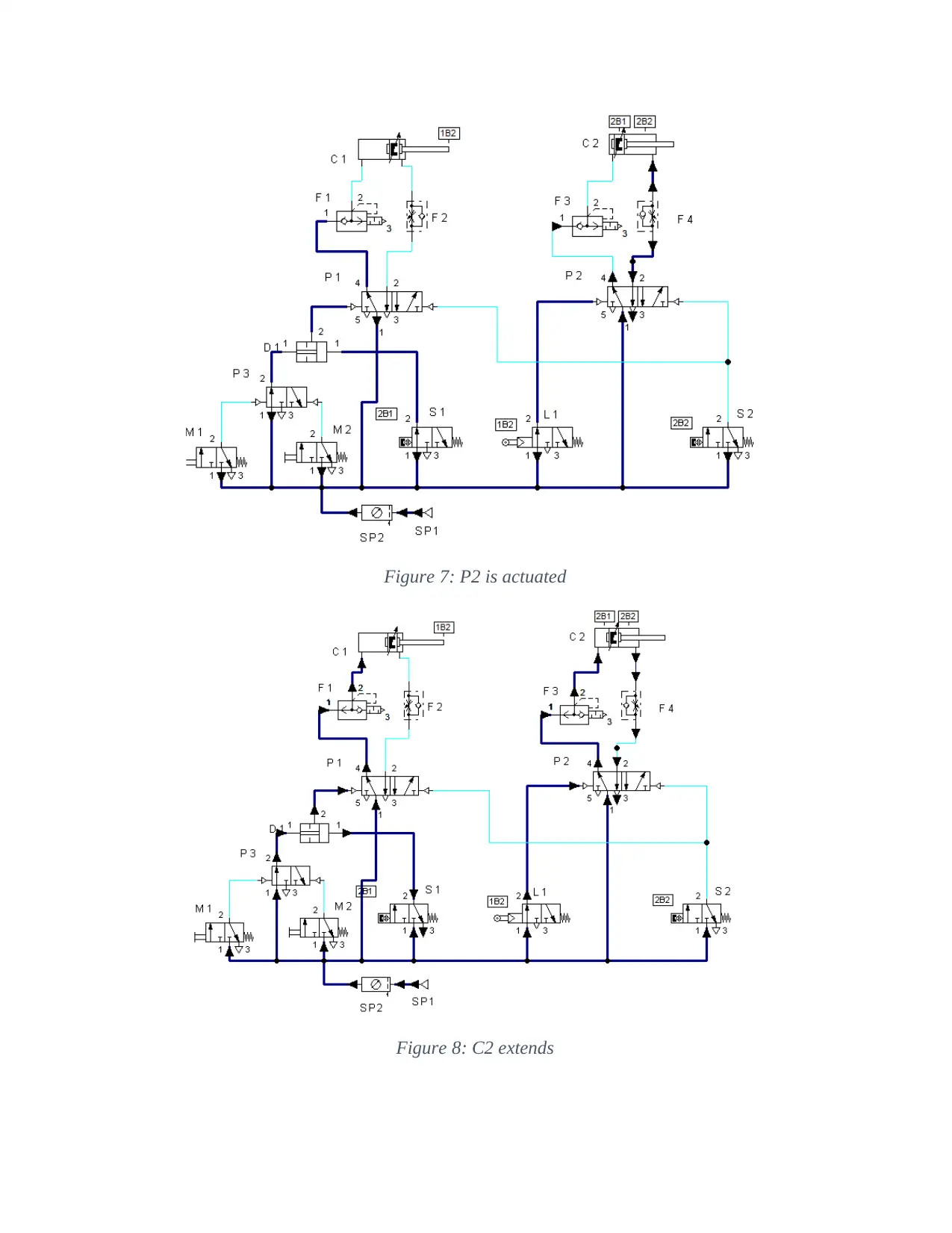
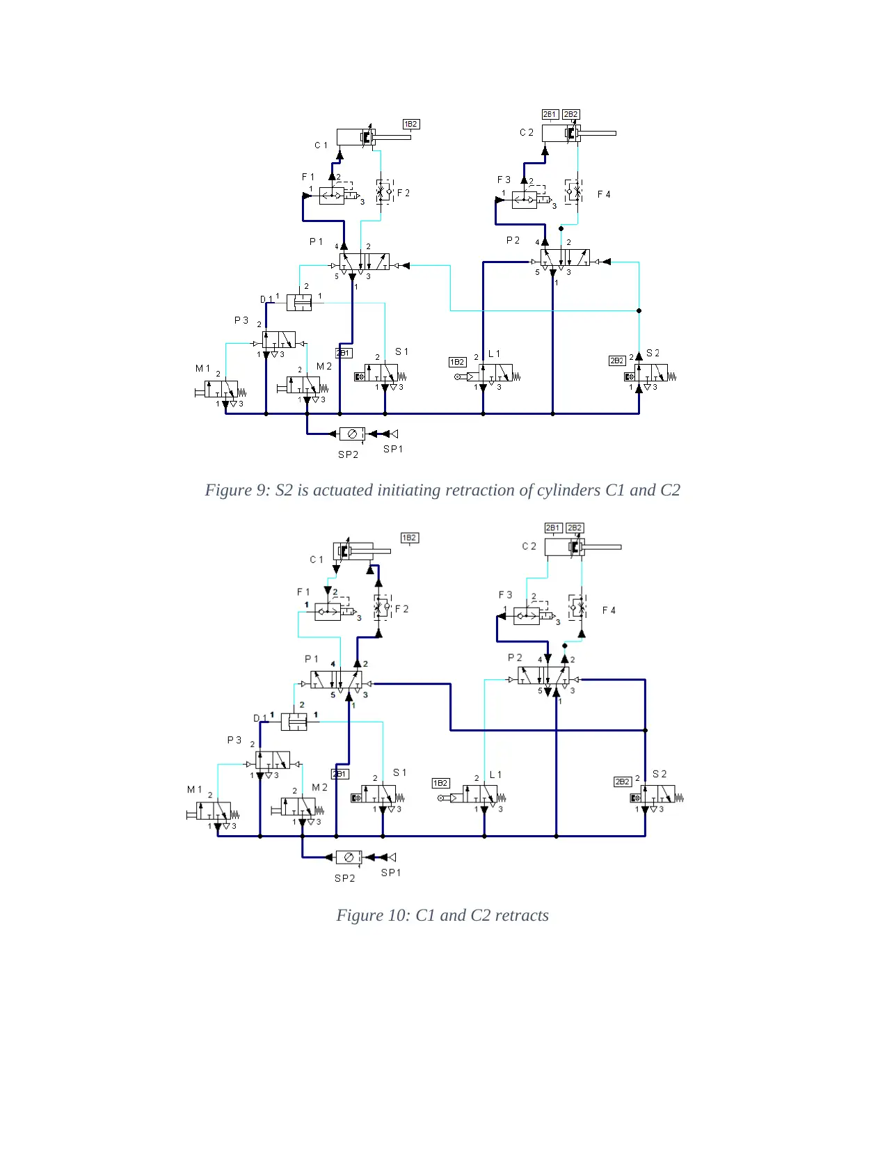
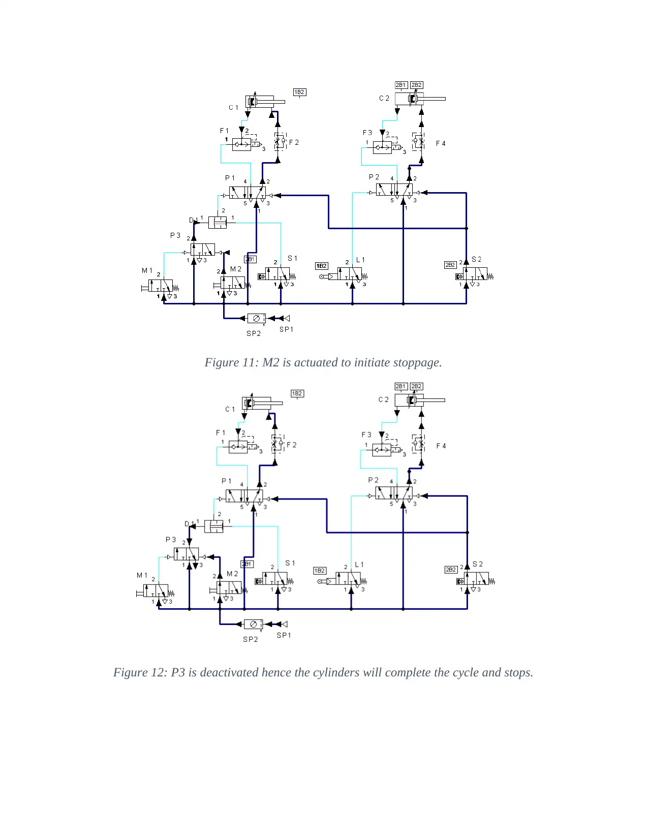
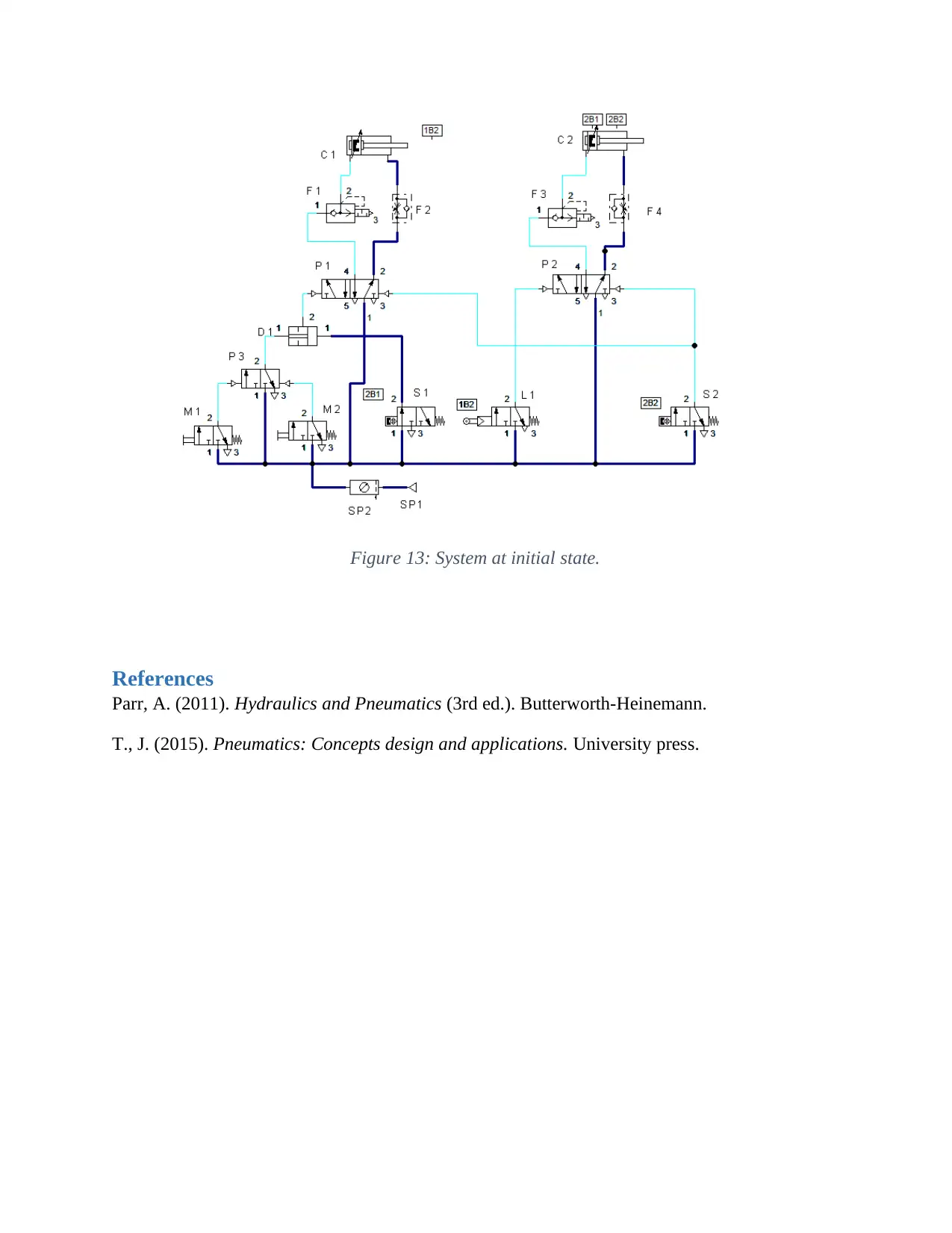
This document presents the solution for the MET230L Hydraulic and Pneumatic Systems Lab Unit 5 Course Project Part 3 assignment. The project involves modifying a pneumatic circuit to achieve a specific cylinder sequence: Cylinder 1 extends, Cylinder 2 extends, and both retract. The solution includes adding components such as a 3/2-way valve with a pushbutton (M2) and a pneumatically operated 3/2-way valve (P3) to the existing circuit. The solution provides a list of added components and their locations within the circuit. The solution also includes a series of screenshots that illustrate each state change of the circuit during simulation, properly labeled and identified, demonstrating the functionality of the redesigned circuit. The cycle is designed to run continuously until a push button of another valve is depressed. Upon actuation of this valve, the current cycle completes before stopping. References for the project include "Hydraulics and Pneumatics" by Parr and "Pneumatics: Concepts design and applications" by T., J.
Document Page
MET230L Hydraulic and Pneumatic Systems Lab
Instructor: Calvin Cox
Unit 5 – Course Project Part 3
tabler-icon-diamond-filled.svg

Paraphrase This Document

Need a fresh take? Get an instant paraphrase of this document with our AI Paraphraser
Document Page
Part 3: Circuit Second Modification
Remember to open a new Word file named MET230_Project_Pt3_LastName_FirstName.doc(x).
In this last phase of the project, you will redesign the circuit to meet desired requirements.
a. Open the Project_Pt2_LastName_FirstName simulation file you created in part 2 of this
project.
b. Rename and save it as Project_Pt3_LastName_FirstName
c. Modify the circuit built in Part 2 by adding any necessary components to produce the
following sequence when the M1 valve push button is depressed.
a. Cylinder 1 extends.
b. Cylinder 2 extends.
c. Both cylinders retract.
d. The cycle repeats continuously until the push button of another valve, to be added
to circuit, is depressed. It is understood that, when this push button is depressed,
the current cycle must complete (run until both cylinders retract) before stopping.
Figure 1: The modified circuit
d. List the name and location of each component you have added to the circuit.
Document Page
M2-3/2-way valve with pushbutton placed between air supply unit and P3
P3-3/2-way valve, pneumatically operated located between M1/M2 and D2.
e. Take a screen shot of EACH STATE CHANGE of the working simulated circuit.
Properly label and identify all screen shots as required by your instructor. Paste your
work below.
Figure 2: M1 is actuated
Document Page
Figure 3: P3 is actuated
Figure 4: P1 is actuated
tabler-icon-diamond-filled.svg

Paraphrase This Document

Need a fresh take? Get an instant paraphrase of this document with our AI Paraphraser
Document Page
Figure 5: C1 extends
Figure 6: L1 is actuated
Document Page
Figure 7: P2 is actuated
Figure 8: C2 extends
Document Page
Figure 9: S2 is actuated initiating retraction of cylinders C1 and C2
Figure 10: C1 and C2 retracts
tabler-icon-diamond-filled.svg

Paraphrase This Document

Need a fresh take? Get an instant paraphrase of this document with our AI Paraphraser
Document Page
Figure 11: M2 is actuated to initiate stoppage.
Figure 12: P3 is deactivated hence the cylinders will complete the cycle and stops.
Document Page
Figure 13: System at initial state.
References
Parr, A. (2011). Hydraulics and Pneumatics (3rd ed.). Butterworth-Heinemann.
T., J. (2015). Pneumatics: Concepts design and applications. University press.
chevron_up_icon
1 out of 9
circle_padding
hide_on_mobile
zoom_out_icon
[object Object]