MET230L: Hydraulic and Pneumatic Systems - Unit 4 Project Modification

Verified

Added on  2022/08/27

|8
|330
|27
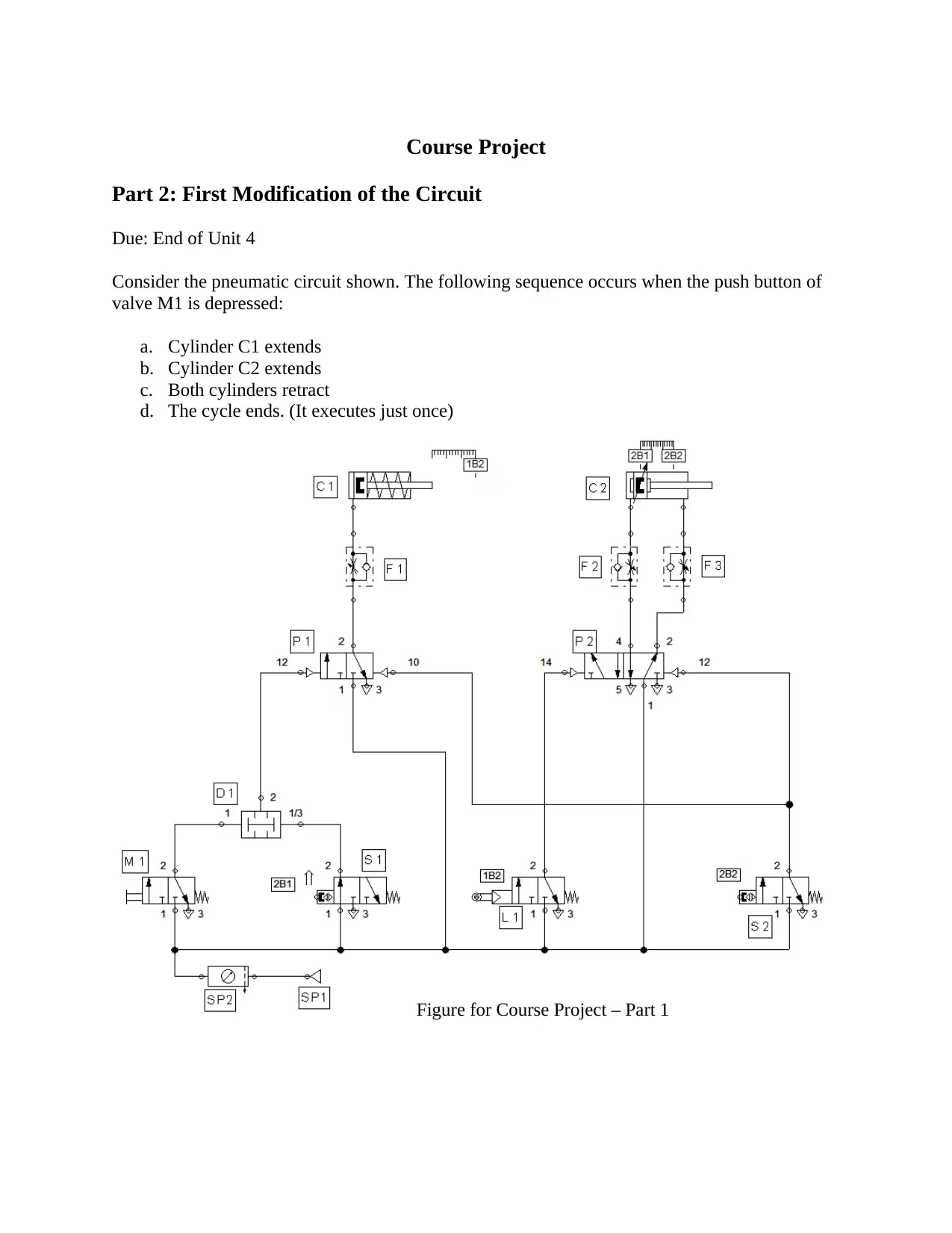
Practical Assignment
AI Summary
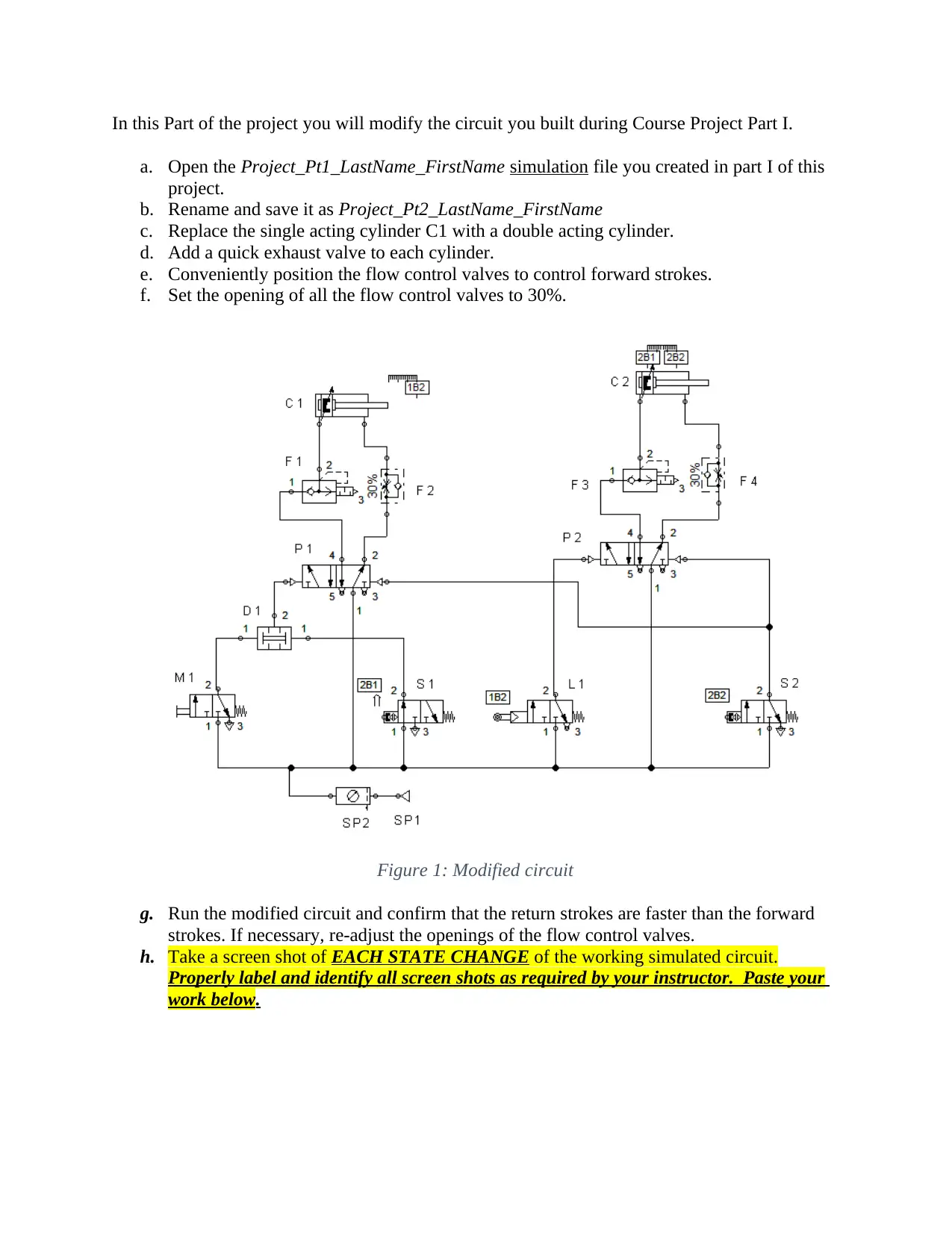
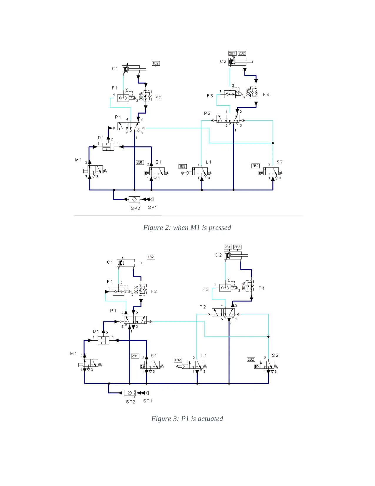
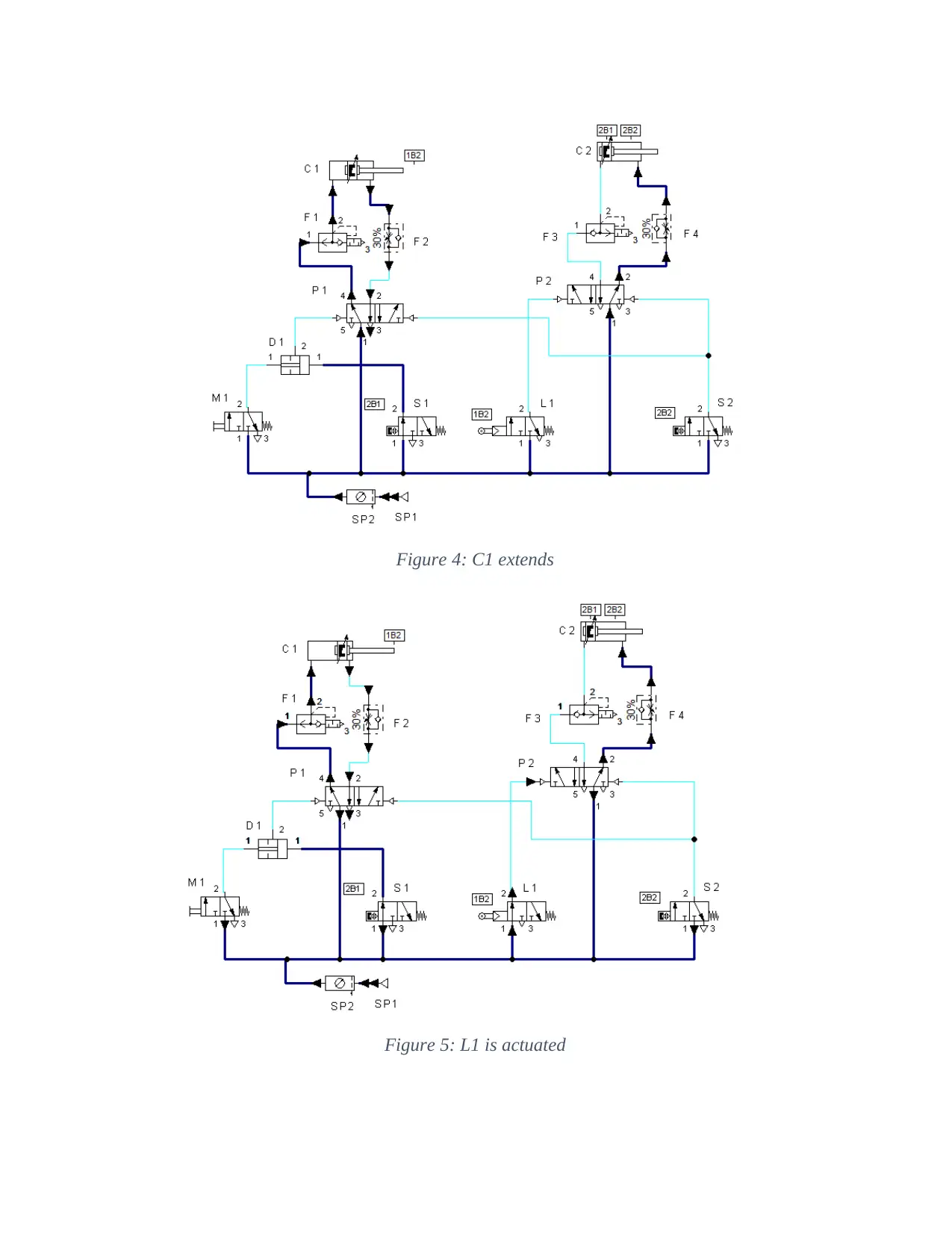
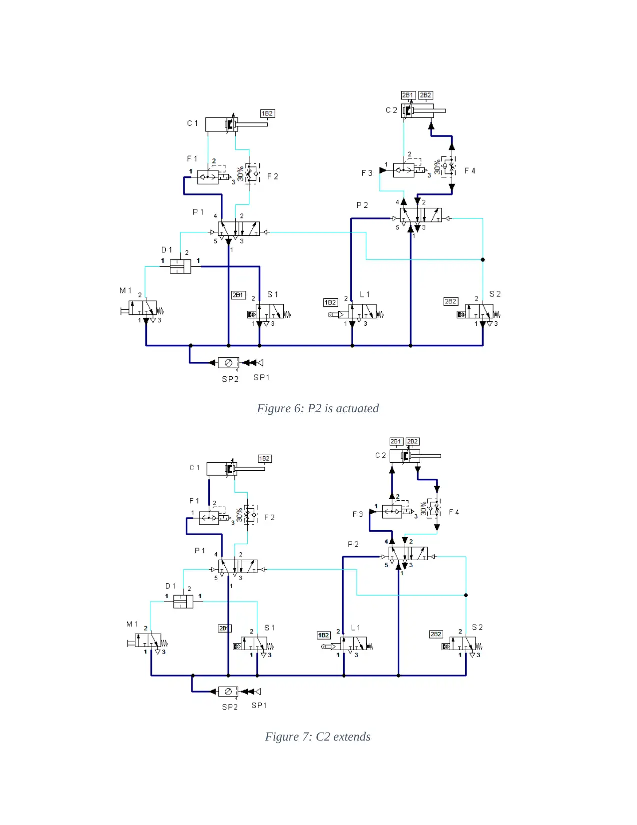
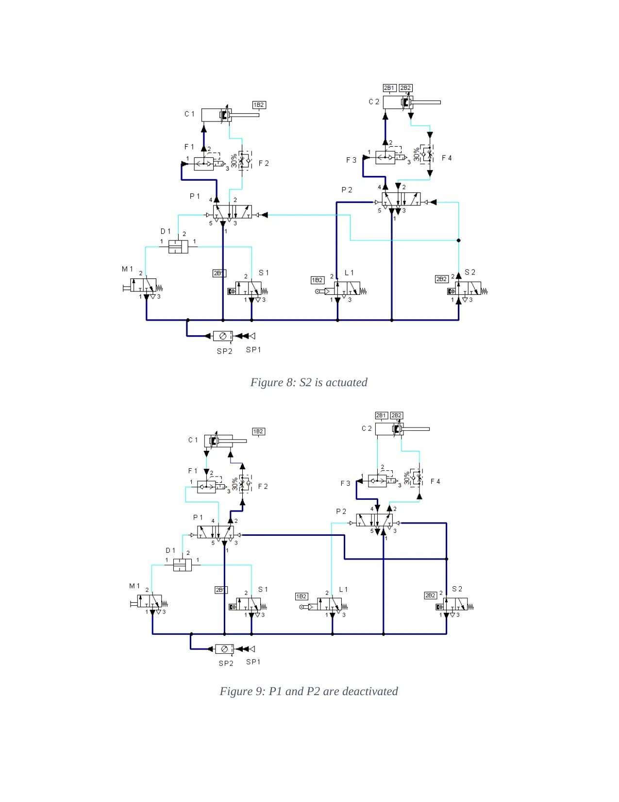
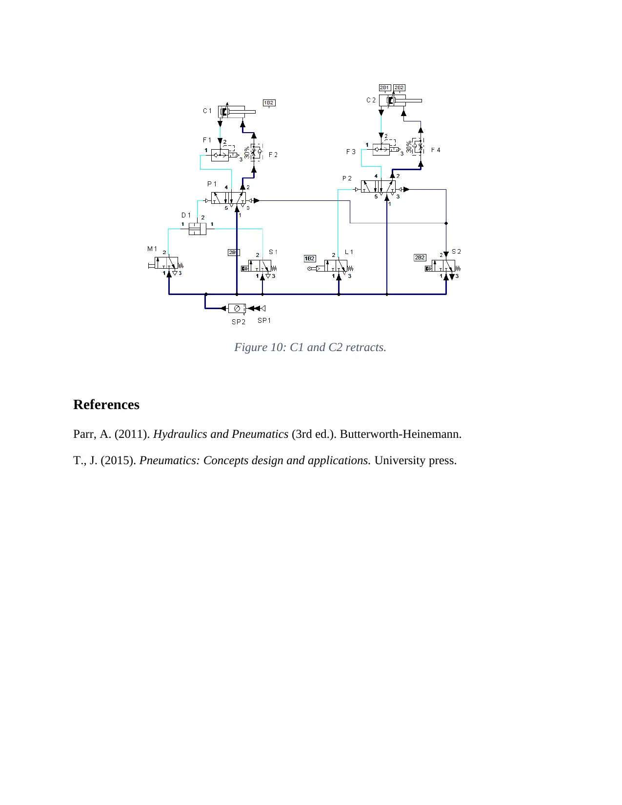
This assignment presents the solution to a mechanical engineering lab project (MET230L) focused on hydraulic and pneumatic systems. The project requires modifying a given pneumatic circuit. The initial circuit, which controls the extension and retraction of two cylinders, is modified by replacing a single-acting cylinder with a double-acting cylinder and adding quick exhaust valves to each cylinder. Flow control valves are strategically positioned to regulate the forward strokes of the cylinders. The student then simulates the modified circuit, adjusting flow control valve openings to achieve faster return strokes. The solution includes screenshots of each state change in the circuit, illustrating the sequence of operations when a push button is depressed, causing the cylinders to extend and retract. The assignment demonstrates practical application of pneumatic components and circuit design principles.
Document Page
MET230L Hydraulic and Pneumatic Systems Lab
Instructor: Calvin Cox
Unit 4 Course Project – Part 2
tabler-icon-diamond-filled.svg

Paraphrase This Document

Need a fresh take? Get an instant paraphrase of this document with our AI Paraphraser
Document Page
Course Project
Part 2: First Modification of the Circuit
Due: End of Unit 4
Consider the pneumatic circuit shown. The following sequence occurs when the push button of
valve M1 is depressed:
a. Cylinder C1 extends
b. Cylinder C2 extends
c. Both cylinders retract
d. The cycle ends. (It executes just once)
Figure for Course Project – Part 1
Document Page
In this Part of the project you will modify the circuit you built during Course Project Part I.
a. Open the Project_Pt1_LastName_FirstName simulation file you created in part I of this
project.
b. Rename and save it as Project_Pt2_LastName_FirstName
c. Replace the single acting cylinder C1 with a double acting cylinder.
d. Add a quick exhaust valve to each cylinder.
e. Conveniently position the flow control valves to control forward strokes.
f. Set the opening of all the flow control valves to 30%.
Figure 1: Modified circuit
g. Run the modified circuit and confirm that the return strokes are faster than the forward
strokes. If necessary, re-adjust the openings of the flow control valves.
h. Take a screen shot of EACH STATE CHANGE of the working simulated circuit.
Properly label and identify all screen shots as required by your instructor. Paste your
work below.
Document Page
Figure 2: when M1 is pressed
Figure 3: P1 is actuated
tabler-icon-diamond-filled.svg

Paraphrase This Document

Need a fresh take? Get an instant paraphrase of this document with our AI Paraphraser
Document Page
Figure 4: C1 extends
Figure 5: L1 is actuated
Document Page
Figure 6: P2 is actuated
Figure 7: C2 extends
Document Page
Figure 8: S2 is actuated
Figure 9: P1 and P2 are deactivated
tabler-icon-diamond-filled.svg

Paraphrase This Document

Need a fresh take? Get an instant paraphrase of this document with our AI Paraphraser
Document Page
Figure 10: C1 and C2 retracts.
References
Parr, A. (2011). Hydraulics and Pneumatics (3rd ed.). Butterworth-Heinemann.
T., J. (2015). Pneumatics: Concepts design and applications. University press.
chevron_up_icon
1 out of 8
circle_padding
hide_on_mobile
zoom_out_icon
[object Object]