MET230L Hydraulic and Pneumatic Systems Lab - Unit 3 Project

Verified

Added on  2022/08/27

|8
|560
|24
Project
AI Summary
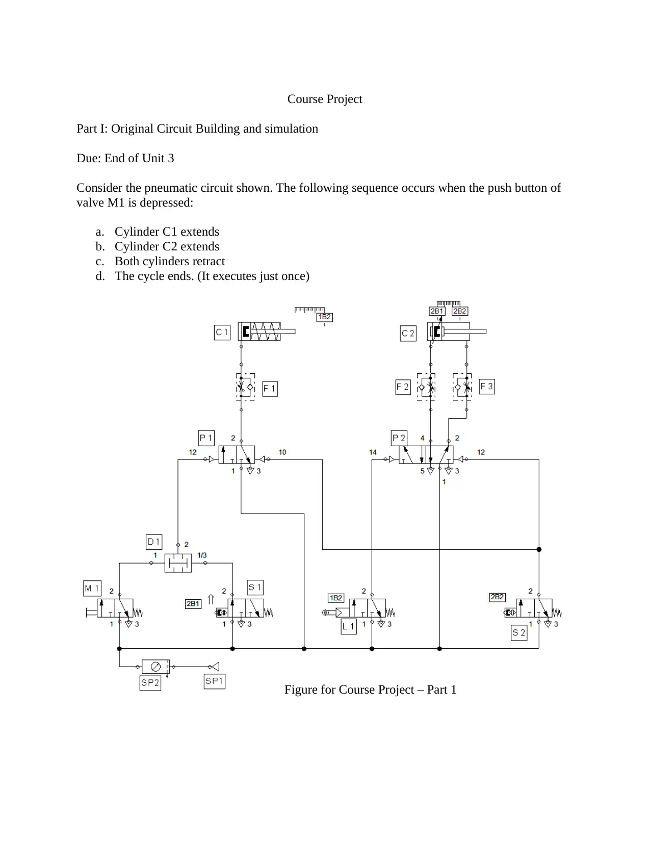
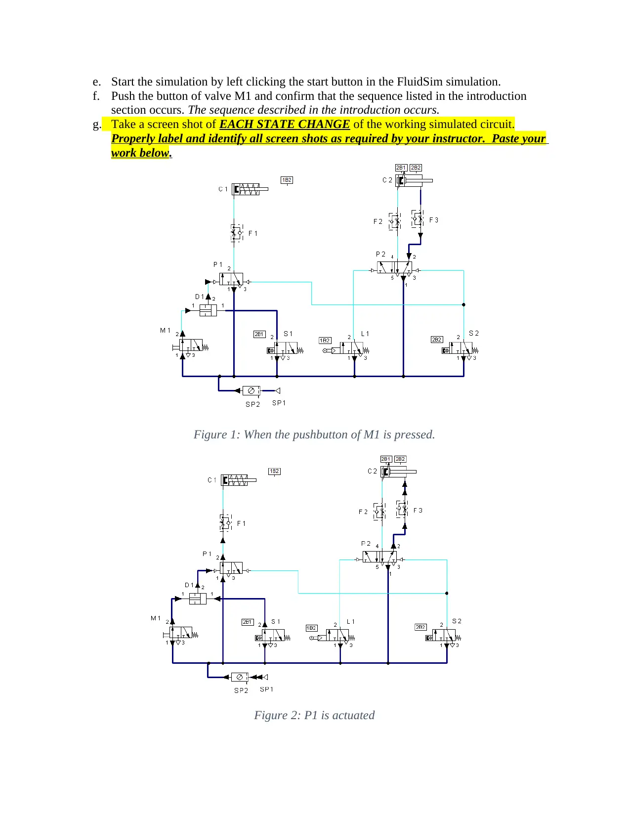
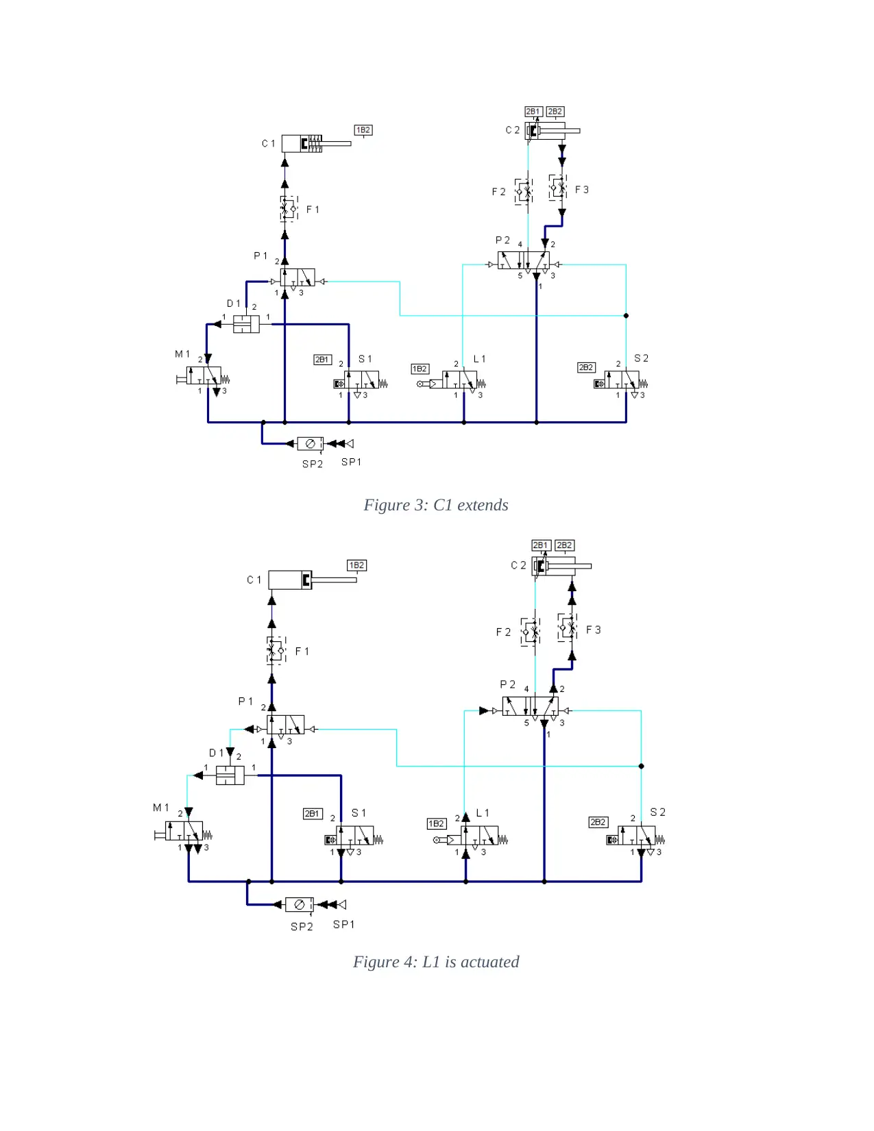
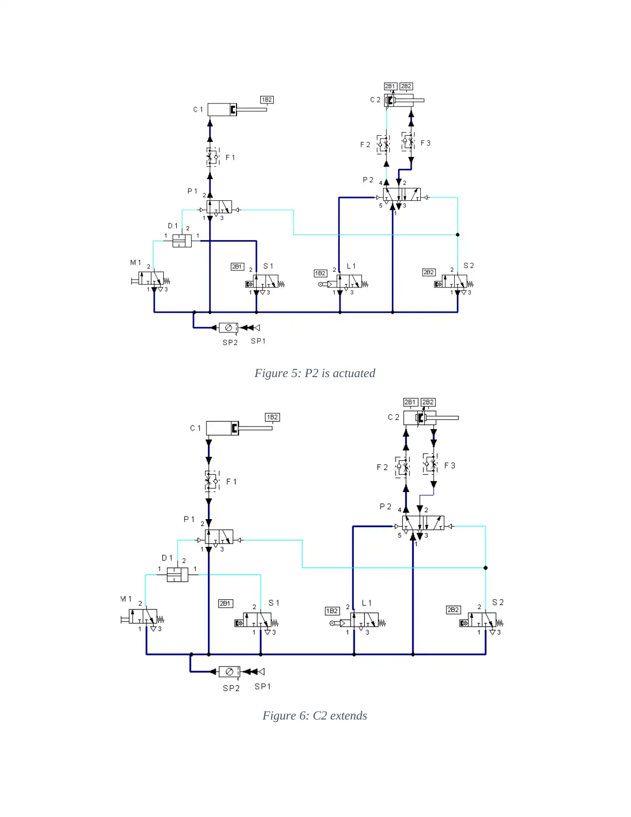
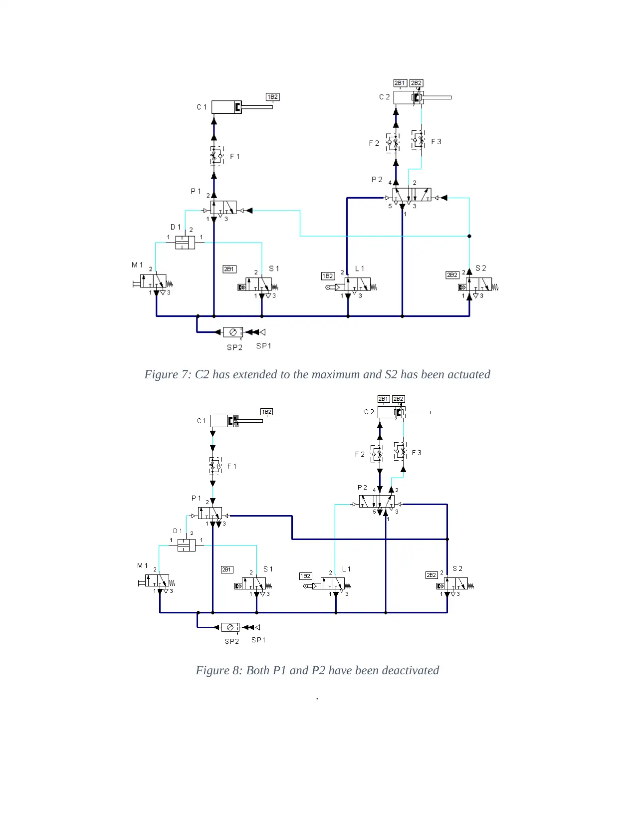
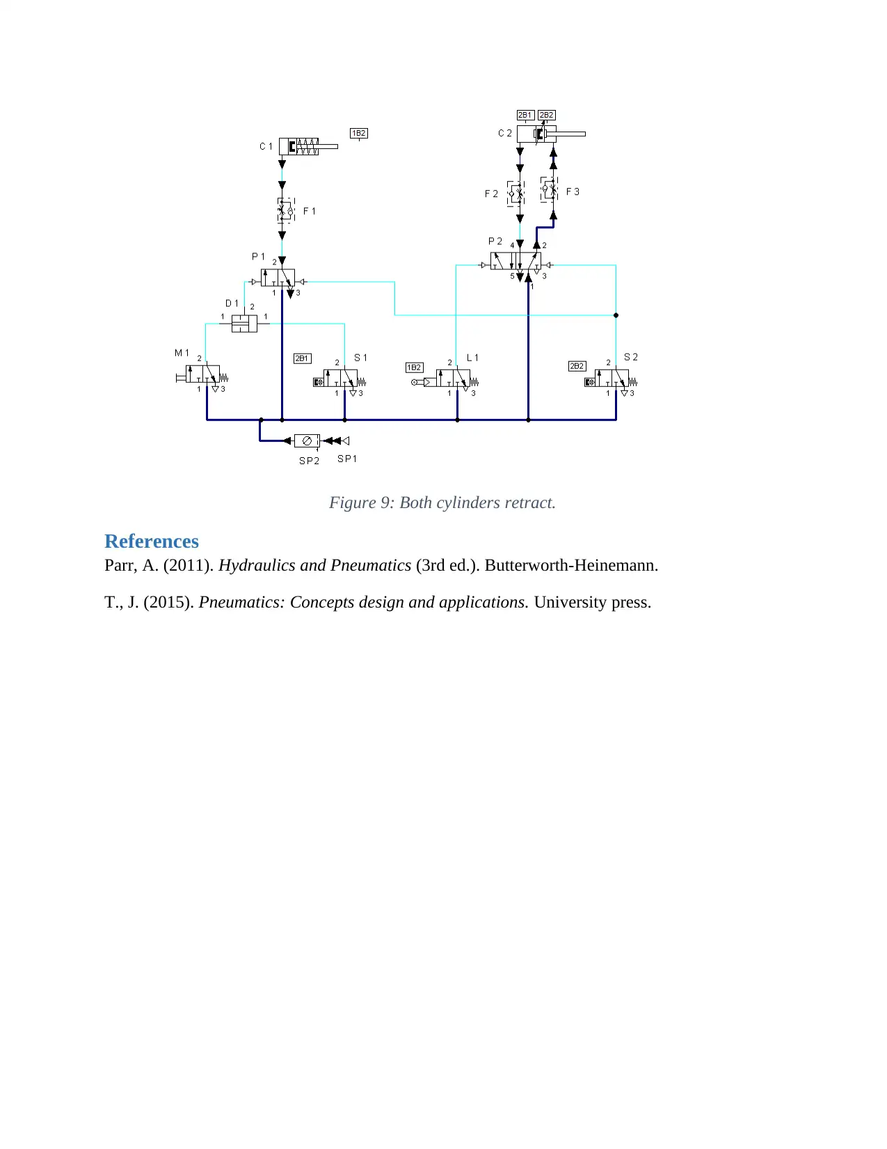
This assignment solution details a MET230L Unit 3 course project focused on hydraulic and pneumatic systems. The project involves designing and simulating a pneumatic circuit. The solution includes a complete component naming, a detailed prediction of the circuit's operational sequence when a push button valve (M1) is activated, and step-by-step simulation results with labeled screenshots for each state change in the circuit. The circuit includes components such as a compressed air supply, various valves (3/2-way, 5/2-way, flow control), cylinders (single and double acting), and proximity switches. The simulation demonstrates the sequence: Cylinder C1 extends, Cylinder C2 extends, and both cylinders retract. The solution follows the instructions, including file naming conventions and references to relevant literature, demonstrating a practical application of pneumatic circuit design and analysis using simulation software.
Document Page
MET230L Hydraulic and Pneumatic Systems Lab
Instructor: Calvin Cox
Unit 3 Course Project – Part 1
.
tabler-icon-diamond-filled.svg

Secure Best Marks with AI Grader

Need help grading? Try our AI Grader for instant feedback on your assignments.
Document Page
Course Project
Part I: Original Circuit Building and simulation
Due: End of Unit 3
Consider the pneumatic circuit shown. The following sequence occurs when the push button of
valve M1 is depressed:
a. Cylinder C1 extends
b. Cylinder C2 extends
c. Both cylinders retract
d. The cycle ends. (It executes just once)
Figure for Course Project – Part 1
Document Page
Use this document to save and present your work. Name it: MET230L Course Project Part
1_LastName_FirstName.docx
Do the following:
a. Fully name all the components of the pneumatic circuit (SP1, SP2, M1, S1, L1, P1, F1,
C1, …)
SP1-Compressed air supply
SP2-Air service unit
M1-3/2-way valve with pushbutton
S1, S2-Pneumatically proximity switch, solenoid operated
L1-3/2-way roller lever switch
P1-3/2-way valve pneumatically operated
P2-5/2-way valve pneumatically operated
F1, F2, F3-one-way flow valve control valve
D1-Two pressure valve
C1-Single acting cylinder
C2-double acting cylinder
b. Predict, in details, the succession of events when the push button of valve M1 is pushed.
When the push button of valve M1 is pushed. P1 is actuated through D1, since
compressed air is now being supplied to both inputs of D1. When P1 is actuated
compressed is supplied to C1 through F1 causing it to extend. When the piston rod
extends and hits the point 1B2 on the measuring rule, L1 is actuated actuating P2.
Compressed air is forced into C2 though F2 causing it to extend to the right. When C2
extends and its piston rod hits point 2B2 on the measuring rule S2 is actuated initiating
the retraction retract stroke of both C1 and C2 by deactivating P1 and P2 respectively.
C1 retracts when P1 is deactivated through the return spring. C2 retracts when P2 is
deactivated and compressed air is allowed to flow to the back of the piston through F3.
c. In the simulation software assigned by your instructor, open a new file named
Project_Pt1_LastName_FirstName.
d. Build the circuit using the components shown or their equivalents.
Document Page
e. Start the simulation by left clicking the start button in the FluidSim simulation.
f. Push the button of valve M1 and confirm that the sequence listed in the introduction
section occurs. The sequence described in the introduction occurs.
g. Take a screen shot of EACH STATE CHANGE of the working simulated circuit.
Properly label and identify all screen shots as required by your instructor. Paste your
work below.
Figure 1: When the pushbutton of M1 is pressed.
Figure 2: P1 is actuated
tabler-icon-diamond-filled.svg

Secure Best Marks with AI Grader

Need help grading? Try our AI Grader for instant feedback on your assignments.
Document Page
Figure 3: C1 extends
Figure 4: L1 is actuated
Document Page
Figure 5: P2 is actuated
Figure 6: C2 extends
Document Page
Figure 7: C2 has extended to the maximum and S2 has been actuated
Figure 8: Both P1 and P2 have been deactivated
.
tabler-icon-diamond-filled.svg

Paraphrase This Document

Need a fresh take? Get an instant paraphrase of this document with our AI Paraphraser
Document Page
Figure 9: Both cylinders retract.
References
Parr, A. (2011). Hydraulics and Pneumatics (3rd ed.). Butterworth-Heinemann.
T., J. (2015). Pneumatics: Concepts design and applications. University press.
chevron_up_icon
1 out of 8
circle_padding
hide_on_mobile
zoom_out_icon
[object Object]