Detailed Hydrogenerator Basic Design Calculation and Analysis

Verified

Added on  2021/07/13

|29
|7112
|321
Homework Assignment
AI Summary
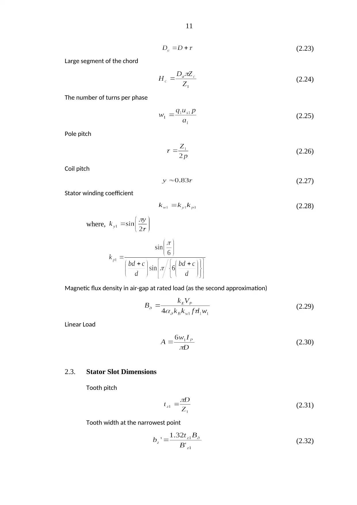
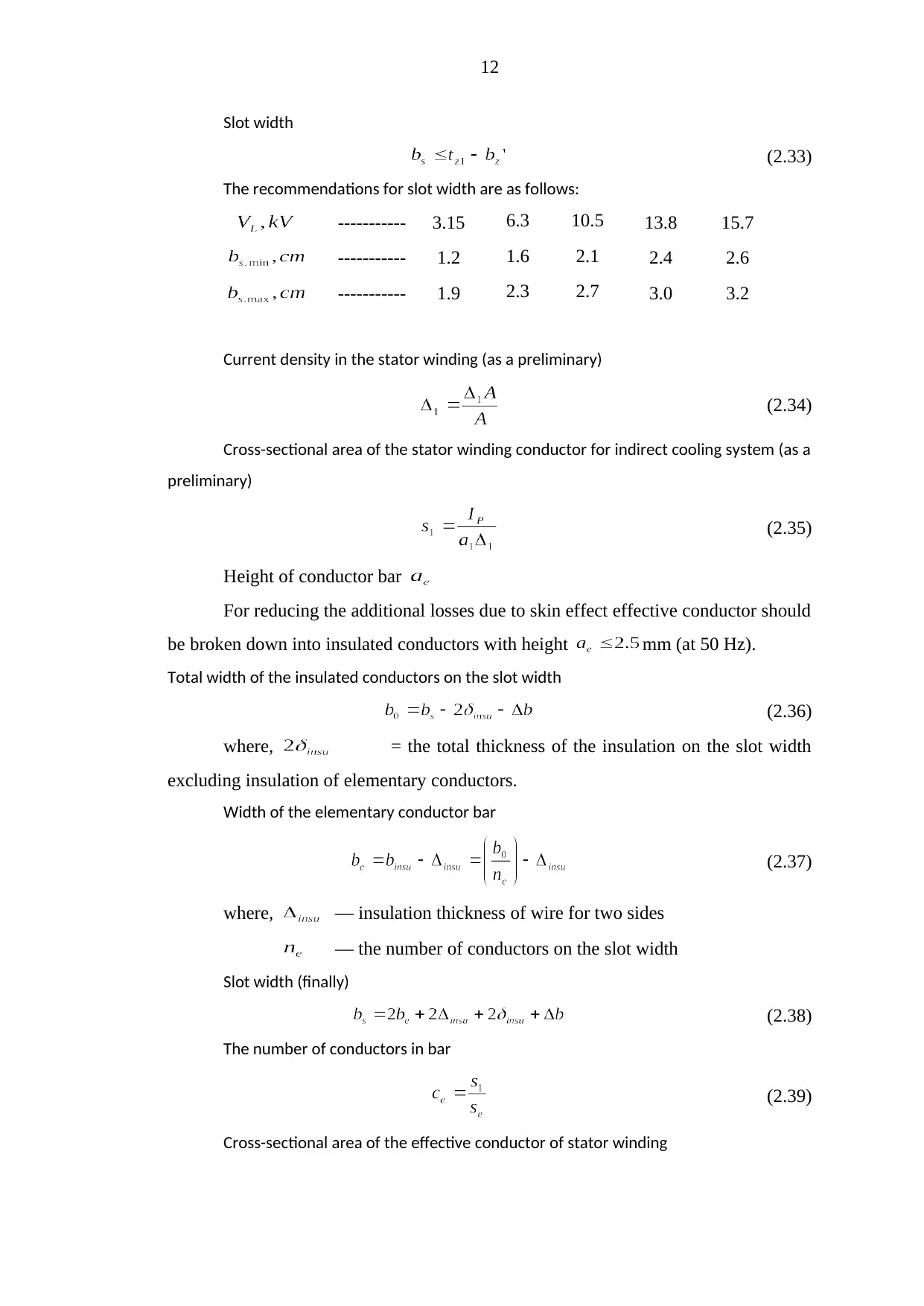
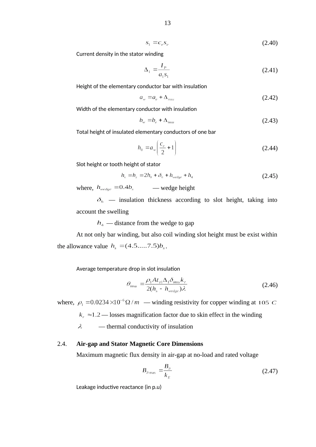
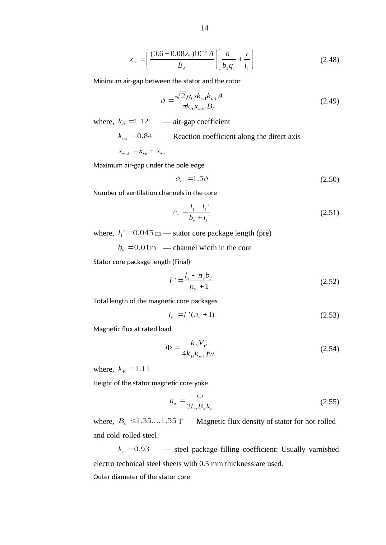
This document presents a detailed basic design calculation for a hydrogenerator, focusing on a 230 MVA rated capacity. It references established textbooks on hydrogenerator and synchronous compensator design. The calculations cover various aspects, starting with basic dimensions like active power and hijacking speed, and progressing to winding type, stator slot dimensions, air-gap, and magnetic core dimensions. It includes formulas for rated phase voltage, current, and number of poles. Detailed calculations are provided for stator slot dimensions, tooth pitch, and current density. Furthermore, it addresses rotor magnetic core and damper winding dimensions, including pole pitch width and dimensions of the damper winding. The document also delves into the magnetic circuit at no-load conditions, providing formulas for the air-gap coefficient and other necessary parameters.
Document Page
CHAPTER 2
HYDROGENERATOR BASIC DESIGN CALCULATION
As a basic case for the consideration of the hydrogenerator losses reduction
and improving its efficiency, hydrogenerators are designed in accordance with the
recommendations of the textbook “Design of Hydrogenerators and Synchronous
Compensators” by A. V. Ivanov-Smolensky, A. I. Abramov and ‘‘Electric Machines
Design ’’ by I. P. Kopilov, B. K. Klakov, V. P. Marozin.
In this thesis, will be calculate Yeywa data hydrogenerator design and
theoretical hydrogenerator design. The rated capacity 230 MVA.
The cost will not be considered in these design calculations.
2.1. Basic Dimensions
Active Power
(2.1)
Hijacking Speed
(2.2)
where, — multiplication factor of hijacking speed
for Pelton turbine
for Francis turbine
for Diagonal Kaplan turbine
for Axial Kaplan turbine
Rated Phase Voltage (Star connection)
(2.3)
Rated Phase Current
(2.4)
No. of Pole Pair
tabler-icon-diamond-filled.svg

Paraphrase This Document

Need a fresh take? Get an instant paraphrase of this document with our AI Paraphraser
Document Page
8
(2.5)
Leakage inductive reactance of stator winding (as a preliminary)
e.m.f at rated load
(2.6)
where, = coefficient
Rated Capacity
(2.7)
And then pole pitch , linear load and magnetic flux density
are previously selected by the value of .
Machine Constant
(2.8)
Moment of inertia of the rotor
(2.9)
where, = angular velocity of rotation
Minimum inner diameter of the stator core
(2.10)
where, = coefficient, depending on the rotor
construction and number of field period
Maximum inner diameter of the stator core
(2.11)
where, m/sec at m and .
m/sec at m and and alloy steel segment
rim.
Document Page
9
m/sec at .
Optimum inner diameter of the stator core
(2.12)
where,
The inner diameter of the stator core must be . If
, take . In contrast, if , take . But
take , if .
Pole pitch at the selected inner diameter of the stator core
(2.13)
Hijacking circumferential velocity at the outer surface of the rotor must not
exceed the allowable values.
(2.14)
Length of the stator yoke
(2.15)
The relative length of the stator magnetic circuit
(2.16)
must be within the allowance value 1.5 to 4.0.
2.2. Winding Type and Number of Stator Slots
For machines with phase current A, especially at voltages
V should be applied double-layer bar type winding, having very reliable
coil insulation. Double-layer coil type lap windings are used in smaller phase currents.
If the number of slots per pole per phase q = 3 and a winding is usually performed
with integer number of slots per pole per phase; If a smaller q - with a fractional
number of slots per pole and phase.
Double-layer bar type wave winding (usually a fractional number of slots per
pole per phase) is mainly used in high-power multi-pole hydrogenerators (at ,
rpm), where they are more favorable to the lap windings by reducing the
Document Page
10
number and length of connections. Lap winding with fractional or integer of slots per
pole per phase is applied in hydrogenerators (at and rpm) and
compensators.
Number of consecutive turns of phase (as a preliminary)
(2.17)
Effective conductors in the slot
for double-layer bar winding;
(even no:) for coil type lap winding;
The number of parallel branches
It must satisfy the inequality;
(2.18)
Stator slot current
(2.19)
The number of slots per pole per phase
(2.20)
If or is different from the nearest integer number of , take
. If , it must be selected fraction, i.e. .
The number of stator slots
(2.21)
The number of slots per segment
(2.22)
where, — the number of stator segments.
— integer number of segments laying in one layer of magnetic core.
The number of stator segments is dependent on the inner diameter of stator.
-----------
----------- 1 2, 4, 6 4, 6, 8
The outer diameter of the stator core (as a preliminary)
tabler-icon-diamond-filled.svg

Paraphrase This Document

Need a fresh take? Get an instant paraphrase of this document with our AI Paraphraser
Document Page
11
(2.23)
Large segment of the chord
(2.24)
The number of turns per phase
(2.25)
Pole pitch
(2.26)
Coil pitch
(2.27)
Stator winding coefficient
(2.28)
where,
Magnetic flux density in air-gap at rated load (as the second approximation)
(2.29)
Linear Load
(2.30)
2.3. Stator Slot Dimensions
Tooth pitch
(2.31)
Tooth width at the narrowest point
(2.32)
Document Page
12
Slot width
(2.33)
The recommendations for slot width are as follows:
----------- 3.15 6.3 10.5 13.8 15.7
----------- 1.2 1.6 2.1 2.4 2.6
----------- 1.9 2.3 2.7 3.0 3.2
Current density in the stator winding (as a preliminary)
(2.34)
Cross-sectional area of the stator winding conductor for indirect cooling system (as a
preliminary)
(2.35)
Height of conductor bar
For reducing the additional losses due to skin effect effective conductor should
be broken down into insulated conductors with height mm (at 50 Hz).
Total width of the insulated conductors on the slot width
(2.36)
where, = the total thickness of the insulation on the slot width
excluding insulation of elementary conductors.
Width of the elementary conductor bar
(2.37)
where, — insulation thickness of wire for two sides
— the number of conductors on the slot width
Slot width (finally)
(2.38)
The number of conductors in bar
(2.39)
Cross-sectional area of the effective conductor of stator winding
Document Page
13
(2.40)
Current density in the stator winding
(2.41)
Height of the elementary conductor bar with insulation
(2.42)
Width of the elementary conductor with insulation
(2.43)
Total height of insulated elementary conductors of one bar
(2.44)
Slot height or tooth height of stator
(2.45)
where, — wedge height
insulation thickness according to slot height, taking into
account the swelling
— distance from the wedge to gap
At not only bar winding, but also coil winding slot height must be exist within
the allowance value .
Average temperature drop in slot insulation
(2.46)
where, — winding resistivity for copper winding at
— losses magnification factor due to skin effect in the winding
— thermal conductivity of insulation
2.4. Air-gap and Stator Magnetic Core Dimensions
Maximum magnetic flux density in air-gap at no-load and rated voltage
(2.47)
Leakage inductive reactance (in p.u)
tabler-icon-diamond-filled.svg

Paraphrase This Document

Need a fresh take? Get an instant paraphrase of this document with our AI Paraphraser
Document Page
14
(2.48)
Minimum air-gap between the stator and the rotor
(2.49)
where, — air-gap coefficient
— Reaction coefficient along the direct axis
Maximum air-gap under the pole edge
(2.50)
Number of ventilation channels in the core
(2.51)
where, m — stator core package length (pre)
m — channel width in the core
Stator core package length (Final)
(2.52)
Total length of the magnetic core packages
(2.53)
Magnetic flux at rated load
(2.54)
where,
Height of the stator magnetic core yoke
(2.55)
where, T — Magnetic flux density of stator for hot-rolled
and cold-rolled steel
— steel package filling coefficient: Usually varnished
electro technical steel sheets with 0.5 mm thickness are used.
Outer diameter of the stator core
Document Page
15
(2.56)
Large cord of stator core segment
(2.57)
2.5. Rotor Magnetic Core and Damper Winding Dimensions
Pole pitch width
(2.58)
where, — overlapping pole coefficient
Arc radius of pole pitch
(2.59)
Pole core length
(2.60)
Calculated pole core length
(2.61)
Damper winding slot pitch
When the slots per pole per phase is integer, and
, slot pitch of the damper winding is selected smaller than stator tooth
pitch .
(2.62)
When , damper winding pitch should be taken as equal size in stator
tooth pitch.
(2.63)
Number of bars per pole
(2.64)
where, (as a preliminary)
Cross-sectional area of copper bar of damper winding
(2.65)
Document Page
16
Cross-sectional area of the damper winding short-circuiting segment
(2.66)
where, and .
Dimensions of slot groove damper winding
m (2.67)
Damper winding bar length
(2.68)
Pole pitch height
For the lack of damper winding and , use the following equation.
And this equation is suited for the massive poles.
(2.69)
For the laminated pole pitch with damper winding use the equation shown
in below.
(2.70)
Pole core height
(2.71)
It should be within the limit m.
Pole core width
It is determined by solving a nonlinear equation with sequential
approximations method. The following inputs are pre-calculated.
Electromotive force of self-induction at rated load
(2.72)
where,
Magnetomotive force of excitation at rated load
(2.73)
where,
Current at rated voltage and no-load condition
tabler-icon-diamond-filled.svg

Paraphrase This Document

Need a fresh take? Get an instant paraphrase of this document with our AI Paraphraser
Document Page
17
(2.74)
Estimated magnetic flux density at pole
(2.75)
Coefficient
(2.76)
The value of
(2.77)
The value of
(2.78)
where,
The value of
For , take . But for , the following
equation is used.
(2.79)
Then the iterative process for determining the pole core width is made
by the algorithm. The initial value at the first iteration (i=1) is calculated by
the following formula.
(2.80)
When it is carried out the first iteration (i=1), determining:
(a) magnetic conductivity for the leakage flux of the poles
(2.81)
where,
Document Page
18
(b) Leakage factor of the poles
(2.82)
(c) Magnetic flux in the pole base
(2.83)
(d) Final value of pole width after the first iteration (i=1)
(2.84)
(e) Relative accuracy of the for the i-th (1st iteration)
(2.85)
Assuming the specified relative accuracy , the
required relative accuracy must be less than or equal to i.e .
Therefore it is necessary to carry out (i+1)th – 2nd iteration and other iterations.
Outer diameter of the rotor rim
(2.86)
Rotor rim length (as a preliminary)
(2.87)
where, m
— width of the excitation winding conductor
Rotor rim height
(2.88)
Inner diameter of the rotor rim
(2.89)
2.6. Magnetic Circuit at No-load Condition
Air-gap coefficient
(2.90)
chevron_up_icon
1 out of 29
circle_padding
hide_on_mobile
zoom_out_icon
[object Object]