iDine System Object Modelling Using Sequence Diagrams
VerifiedAdded on 2023/05/28
|11
|2500
|105
Practical Assignment
AI Summary
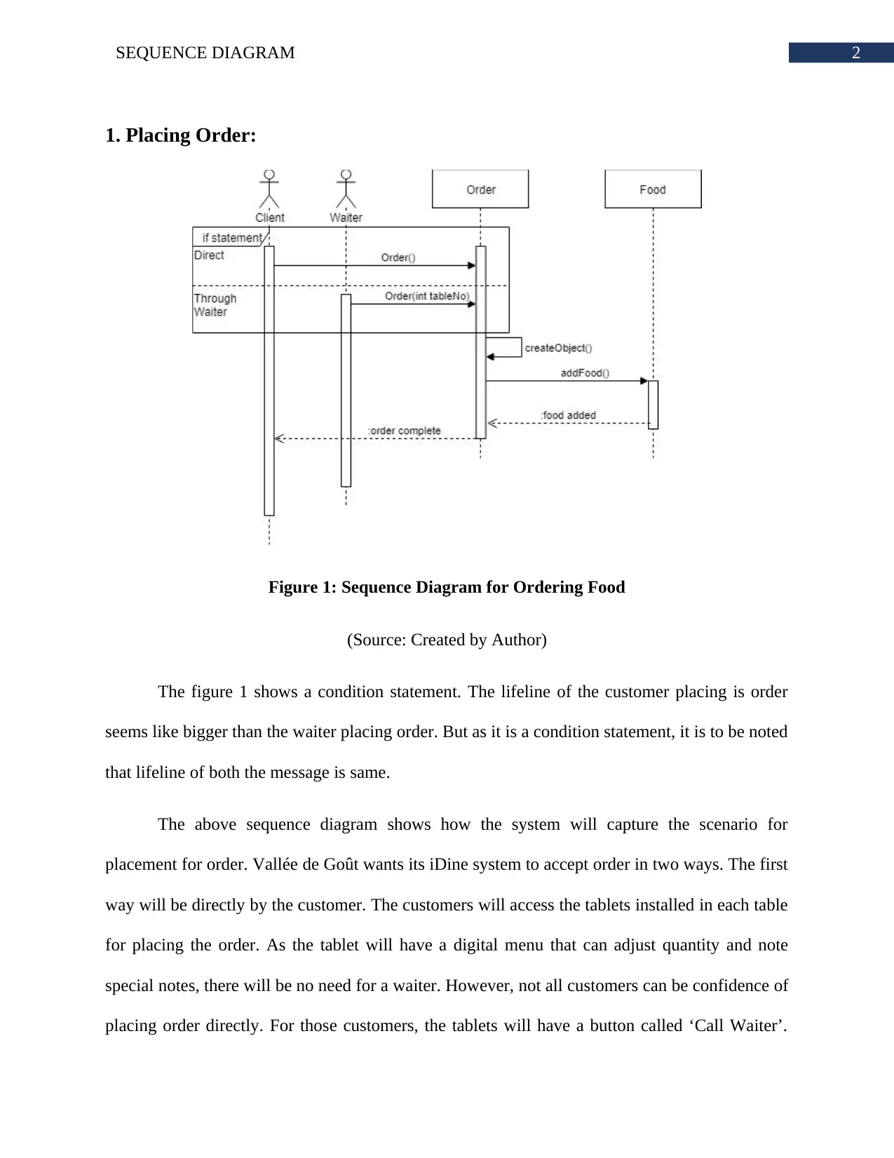
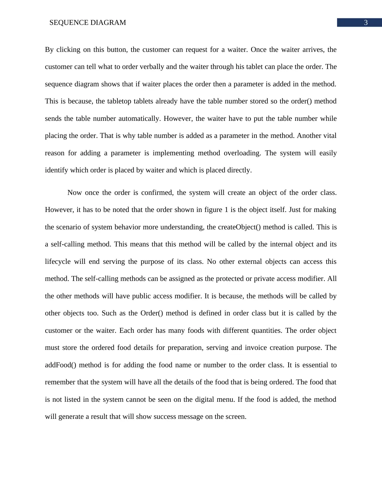
This assignment provides a detailed validation of the iDine system for the Vallée de Goût restaurant using sequence diagrams. It covers three key areas: placing orders, order preparation and serving, and inventory management. The sequence diagrams illustrate the system's behavior in capturing orders directly from customers or through waiters, managing food preparation across different kitchen areas, and updating inventory based on orders and manual checks. The diagrams highlight the interaction between various system components such as customer tablets, waiter tablets, kitchen printers, and the central order management system. Each process is broken down into methods and object interactions, demonstrating how the system supports efficient customer service and operational management. The assignment also addresses real-world scenarios, such as handling waiter requests, managing food quantities, and updating inventory discrepancies, to ensure the system's robustness and adaptability. This document is available on Desklib, a platform offering a range of study tools and solved assignments for students.

Running head: SEQUENCE DIAGRAM
Sequence Diagram
Name of the Student
Name of the University
Author’s note:
Sequence Diagram
Name of the Student
Name of the University
Author’s note:
Secure Best Marks with AI Grader
Need help grading? Try our AI Grader for instant feedback on your assignments.

1SEQUENCE DIAGRAM
Table of Contents
1. Placing Order:..............................................................................................................................2
2. Order Preparation and Serving:...................................................................................................4
3. Inventory Management:...............................................................................................................6
Bibliography:...................................................................................................................................8

2SEQUENCE DIAGRAM
1. Placing Order:
Figure 1: Sequence Diagram for Ordering Food
(Source: Created by Author)
The figure 1 shows a condition statement. The lifeline of the customer placing is order
seems like bigger than the waiter placing order. But as it is a condition statement, it is to be noted
that lifeline of both the message is same.
The above sequence diagram shows how the system will capture the scenario for
placement for order. Vallée de Goût wants its iDine system to accept order in two ways. The first
way will be directly by the customer. The customers will access the tablets installed in each table
for placing the order. As the tablet will have a digital menu that can adjust quantity and note
special notes, there will be no need for a waiter. However, not all customers can be confidence of
placing order directly. For those customers, the tablets will have a button called ‘Call Waiter’.

3SEQUENCE DIAGRAM
By clicking on this button, the customer can request for a waiter. Once the waiter arrives, the
customer can tell what to order verbally and the waiter through his tablet can place the order. The
sequence diagram shows that if waiter places the order then a parameter is added in the method.
This is because, the tabletop tablets already have the table number stored so the order() method
sends the table number automatically. However, the waiter have to put the table number while
placing the order. That is why table number is added as a parameter in the method. Another vital
reason for adding a parameter is implementing method overloading. The system will easily
identify which order is placed by waiter and which is placed directly.
Now once the order is confirmed, the system will create an object of the order class.
However, it has to be noted that the order shown in figure 1 is the object itself. Just for making
the scenario of system behavior more understanding, the createObject() method is called. This is
a self-calling method. This means that this method will be called by the internal object and its
lifecycle will end serving the purpose of its class. No other external objects can access this
method. The self-calling methods can be assigned as the protected or private access modifier. All
the other methods will have public access modifier. It is because, the methods will be called by
other objects too. Such as the Order() method is defined in order class but it is called by the
customer or the waiter. Each order has many foods with different quantities. The order object
must store the ordered food details for preparation, serving and invoice creation purpose. The
addFood() method is for adding the food name or number to the order class. It is essential to
remember that the system will have all the details of the food that is being ordered. The food that
is not listed in the system cannot be seen on the digital menu. If the food is added, the method
will generate a result that will show success message on the screen.
Secure Best Marks with AI Grader
Need help grading? Try our AI Grader for instant feedback on your assignments.

4SEQUENCE DIAGRAM
After the customer has ordered all the desired food, the system will ask for confirmation.
As this confirmation is just an alert or similar kind of function, it will not be visible on the
sequence diagram. The alert is an internal property of methods. The ordered food data is then
circulated in the system for further operations to be completed. Once the order is placed and
acknowledged by the system, the system will show the message on the screen of either the
customer or the waiter that order is placed.
2. Order Preparation and Serving:
Figure 2: Sequence Diagram for Food Preparation and Serving
(Source: Created by Author)
The firgur2 shows the sequence diagram of how the food is prepared. The diagram also
visualizes how the system supports the process of serving food. The kitchen at Vallée de Goût is
divided into many parts based on the food they prepare. Each kitchen area has its own printer.
The printer is for printing the order into paper forms that the cooks will use. The system will
automatically decide the type of the food. The foodName() method initiates the process. This
method collects both the food name and food type. The food name is for printing and food type

5SEQUENCE DIAGRAM
for deciding to which kitchen area it is to be printed. After the food name and type is identified,
the system makes a list of food name and quantity to be prepared. This list is categorized as per
the type of the food. Each of these methods will be public access modifier.
There is one thing to be remembered that the system will not actually record which cook
is receiving the printout or which cook is preparing the food. The kitchen is one of the busiest
areas in the whole Vallée de Goût restaurant. There will be not time for the cooks to interact with
the system. Therefore, the system will create a single object of cook. As the payment to the staff
or attendance is not the concern here, in the sequence diagrams or whole system scenario
considering the cook as individual human resources is not necessary. However, the system will
store the type of food which kitchen are prepares. This is because, it will be mandatory for
realizing to which area, the food list is to be printed. There can be some protocols or time
sequence based on which the orders are printed but these complex scenarios are best to avoid
while making a sequence diagram that shows the true dynamic nature of the Vallée de Goût
information system.
After the food is complete the cook will inform the waiter head. The cook will inform the
waiter head that the food is complete only after mentioned quantity is prepared. There will be a
limit to ordering quantity of food. No person can order more than five of the same foods at once.
This is because, Vallée de Goût put immense focus on the quality of the food they prepare. If a
lot of food is order at same time, the first food prepared will get cold and the quality will
diminish. Once the food is complete, the cook will click on the complete button. There may be
one person who will handle the process of receiving the order and marking it as complete.
However, that concern has not been visualized in this scenario. The system will receive the
message that order is complete and change the status of the order from preparing to complete

6SEQUENCE DIAGRAM
once all the foods mentioned in the order is completed. This process shows a possibility of
waiting. For this reason, the system must have a powerful processor that can handle a lost or
request. Once the order is marked as complete, the system will inform the waiter head about it.
The waiter head will have tablet that is also connected to Vallée de Goût system. The system will
show a notification that will have order id and the table number. After clicking on the
notification, the waiter head can see the food details. The waiter head then click on assign waiter,
the list if available waiter name appears on screen, the waiter head click on any name and the
order details are sent to that waiter’s tablet. The waiter then serve the food and click on order
served.
3. Inventory Management:
Figure 3: Sequence Diagram for Inventory Report and Update
(Source: Created by Author)
Paraphrase This Document
Need a fresh take? Get an instant paraphrase of this document with our AI Paraphraser

7SEQUENCE DIAGRAM
The figure 3, also shows a condition statement. The statement is shown for the reason
behind updating the inventory. The reason is not included into the system, it is shown in the
sequence diagram just for showing the system can support real life scenarios. The sequence
diagram visualized in figure 3 is created for showing how the system incorporates the process of
managing inventory. The first method is checkInventory(). This method is applied when
management wants to check the physical availability of the ingredients. The quantity of the
ingredient can be manually updated in the system. The system automatically deducts the amount
of ingredient required to create a food and maintains the inventory data updated. However, it is
essential that the management manually checks the actual physical availability of the ingredients
and update the inventory if the data stored in system does not match with actual measurements.
Once the checkInventory() method is called by the management, the order class object
will calculate how many foods are ordered and which food requires how many ingredients. It is
to be remembered that the report is generated based on the time period mentioned in the
checkInventory() method. It is because, the report also has a result called total quantity used and
this has to be based on a time. The checkInventory() method lifeline ends when the report is
generated. Now, the update inventory process is done in the system. There are two reasons for
updating the inventory details. The first one is that ingredients are ordered from the suppliers and
the ordered quantities have to be updated into the system. The other reason is that the quantity
that system shows does not match with original availability. However, in both cases, the process
of updating the inventory is same and follows the same procedure. After the inventory is
updated, the system will show the available quantity of ingredients on the screen. The system
will not store the details of the management separately like waiters or customers. It is because,
storing the details of which management requested for report or which management updated the

8SEQUENCE DIAGRAM
inventory is not required as per the scenario provided. The system will only do the process as per
management requests.
inventory is not required as per the scenario provided. The system will only do the process as per
management requests.

9SEQUENCE DIAGRAM
Bibliography:
El Ahmar, Y., Le Pallec, X., & Gerard, S. (2016). Empirical Activity: Assessing the Perceptual
Properties of the Size Visual Variation in UML Sequence Diagram. In HuFaMo
workshop.
Gogolla, M., Hilken, F., Niemann, P., & Wille, R. (2017, July). Formulating model verification
tasks prover-independently as UML diagrams. In European Conference on Modelling
Foundations and Applications (pp. 232-247). Springer, Cham.
Jena, A. K., Swain, S. K., & Mohapatra, D. P. (2015). Test case creation from UML sequence
diagram: a soft computing approach. In Intelligent Computing, Communication and
Devices (pp. 117-126). Springer, New Delhi.
Kumar, B., & Singh, K. (2015). Testing uml designs using class, sequence and activity
diagrams. International Journal for Innovative Research in Science and
Technology, 2(3), 71-81.
Lyu, K., Noda, K., & Kobayashia, T. (2018, May). SDExplorer: a generic toolkit for smoothly
exploring massive-scale sequence diagram. In Proceedings of the 26th Conference on
Program Comprehension (pp. 380-384). ACM.
Mohapatra, D. P., Godbley, S., & Dutta, A. (2017). Measuring Hit ratio of Software Systems
using UML Sequence Diagram.
Muram, F. U., Tran, H., & Zdun, U. (2016, December). A model checking based approach for
containment checking of uml sequence diagrams. In Software Engineering Conference
(APSEC), 2016 23rd Asia-Pacific (pp. 73-80). IEEE.
Secure Best Marks with AI Grader
Need help grading? Try our AI Grader for instant feedback on your assignments.

10SEQUENCE DIAGRAM
Rhmann, W., & Saxena, V. (2016). Generation of Test Cases from UML Sequence Diagram
Based on Extenics Theory. British Journal of Mathematics & Computer Science, 16(1).
Rhmann, W., & Saxena, V. (2016). Test Case Generation from UML Sequence Diagram for
Aadhaar Card Number based ATM System. system, 11(4).
Shen, H., Krishnan, R., Slavin, R., & Niu, J. (2016). Sequence Diagram Aided Privacy Policy
Specification. IEEE Transactions on Dependable and Secure Computing, 13(3), 381-393.
Soares, J. A. C. (2017). Automatic Model Transformation from UML Sequence Diagrams to
Coloured Petri Nets.
Song, J., Zhou, Z., & Guan, Y. (2015). Agent UML sequence diagram and meta-
model. American Journal of Engineering and Technology Research, 15(1).
Torre, D., Labiche, Y., Genero, M., & Elaasar, M. (2018). A systematic identification of
consistency rules for UML diagrams. Journal of Systems and Software.
Torre, D., Labiche, Y., Genero, M., Baldassarre, M. T., & Elaasar, M. (2018, May). UML
diagram synthesis techniques: a systematic mapping study. In 2018 IEEE/ACM 10th
International Workshop on Modelling in Software Engineering (MiSE) (pp. 33-40).
IEEE.
Xia, Y. W., Lv, S. D., & Liu, D. X. (2017). Research of Operation Semantic and PI
Transformation Based on UML Sequence Diagrams. Journal of Software
Engineering, 11, 47-53.
1 out of 11
Related Documents

Your All-in-One AI-Powered Toolkit for Academic Success.
+13062052269
info@desklib.com
Available 24*7 on WhatsApp / Email
Unlock your academic potential
© 2024 | Zucol Services PVT LTD | All rights reserved.