IMAT5205 Assignment 2: UML Diagrams for System Analysis
VerifiedAdded on 2023/05/28
|10
|2321
|475
Report
AI Summary
This report provides a comprehensive analysis of UML diagrams, specifically focusing on the 'Record New Tour' use case within a tour management system (TMS). The report includes detailed explanations and illustrations of class diagrams, communication diagrams, and sequence diagrams. The class diagram outlines the relationships between different classes within the system, such as the tour manager, branch manager, tour leader, and finance officer. The communication diagram illustrates the flow of data and control between objects and actors, highlighting the process of a client logging in, viewing tour packages, making inquiries, and booking tours, including the condition for payment authentication. The sequence diagram further elaborates on the interactions between objects, emphasizing the order in which functions are executed. The report also evaluates enterprise architecture (EA) tools, such as Sparx Systems, discussing their benefits in designing and visualizing system requirements, code generation, and overall system understanding. References to relevant literature support the analysis.
Running Head: UML DIAGRAMS 0 | P a g e
UML Diagrams
Individual Task
Student name
UML Diagrams
Individual Task
Student name
Paraphrase This Document
Need a fresh take? Get an instant paraphrase of this document with our AI Paraphraser
UML diagrams 1 | P a g e
Contents
Part 1 Use Case Realization for the ‘Record New Tour’ Use Case.................................................2
Analysis Class Diagram...............................................................................................................2
Communication Diagram.............................................................................................................4
Part 2 Sequence Diagram.................................................................................................................5
Part 3 Evaluation..............................................................................................................................6
References........................................................................................................................................9
UML diagrams 2 | P a g e
Part 1 Use Case Realization for the ‘Record New Tour’ Use Case
Analysis Class Diagram
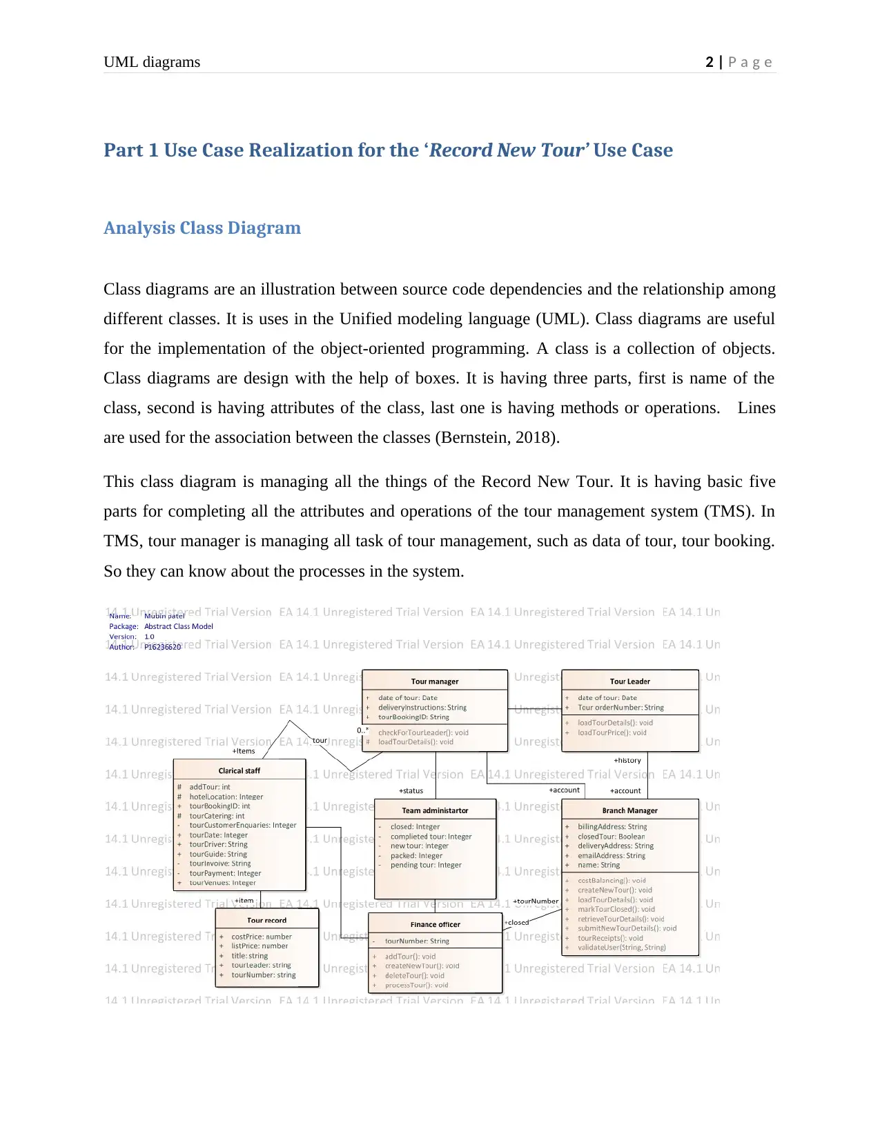
Class diagrams are an illustration between source code dependencies and the relationship among
different classes. It is uses in the Unified modeling language (UML). Class diagrams are useful
for the implementation of the object-oriented programming. A class is a collection of objects.
Class diagrams are design with the help of boxes. It is having three parts, first is name of the
class, second is having attributes of the class, last one is having methods or operations. Lines
are used for the association between the classes (Bernstein, 2018).
This class diagram is managing all the things of the Record New Tour. It is having basic five
parts for completing all the attributes and operations of the tour management system (TMS). In
TMS, tour manager is managing all task of tour management, such as data of tour, tour booking.
So they can know about the processes in the system.
Part 1 Use Case Realization for the ‘Record New Tour’ Use Case
Analysis Class Diagram
Class diagrams are an illustration between source code dependencies and the relationship among
different classes. It is uses in the Unified modeling language (UML). Class diagrams are useful
for the implementation of the object-oriented programming. A class is a collection of objects.
Class diagrams are design with the help of boxes. It is having three parts, first is name of the
class, second is having attributes of the class, last one is having methods or operations. Lines
are used for the association between the classes (Bernstein, 2018).
This class diagram is managing all the things of the Record New Tour. It is having basic five
parts for completing all the attributes and operations of the tour management system (TMS). In
TMS, tour manager is managing all task of tour management, such as data of tour, tour booking.
So they can know about the processes in the system.
⊘ This is a preview!⊘
Do you want full access?
Subscribe today to unlock all pages.
Trusted by 1+ million students worldwide

UML diagrams 3 | P a g e
Source: Author
Branch manager is handling the different activities of the branch of tour agencies. It has tour
leader class, which are responsible for the handling the particular tour and they can also deal
about the price of the tour for making profit for the system. Finance officer is responsible for
providing permission to the clerical staff in few situations, such as payment is more than £1500
(Bruegge, 2008).
Class diagrams are providing a layout of a project, which is directly converted in the code with
the help of code generator. There are few things, which are necessary to selection of the
softwares classes. Proper selection of software classes is difficult for programmer. Therefore,
they take softwares helps and take classes from the help of use cases of the project requirements
(Conallen, 2012).
Paraphrase This Document
Need a fresh take? Get an instant paraphrase of this document with our AI Paraphraser
UML diagrams 4 | P a g e
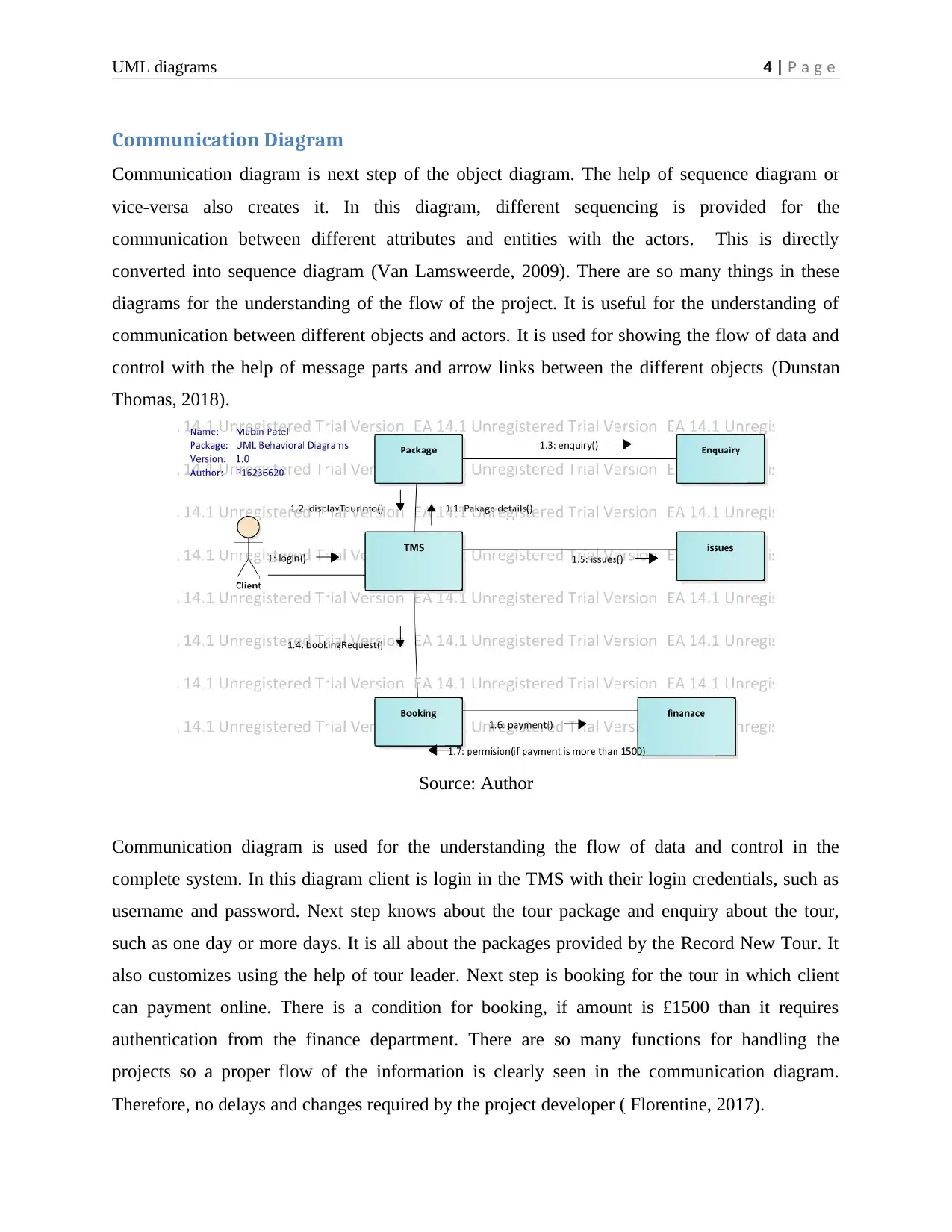
Communication Diagram
Communication diagram is next step of the object diagram. The help of sequence diagram or
vice-versa also creates it. In this diagram, different sequencing is provided for the
communication between different attributes and entities with the actors. This is directly
converted into sequence diagram (Van Lamsweerde, 2009). There are so many things in these
diagrams for the understanding of the flow of the project. It is useful for the understanding of
communication between different objects and actors. It is used for showing the flow of data and
control with the help of message parts and arrow links between the different objects (Dunstan
Thomas, 2018).
Source: Author
Communication diagram is used for the understanding the flow of data and control in the
complete system. In this diagram client is login in the TMS with their login credentials, such as
username and password. Next step knows about the tour package and enquiry about the tour,
such as one day or more days. It is all about the packages provided by the Record New Tour. It
also customizes using the help of tour leader. Next step is booking for the tour in which client
can payment online. There is a condition for booking, if amount is £1500 than it requires
authentication from the finance department. There are so many functions for handling the
projects so a proper flow of the information is clearly seen in the communication diagram.
Therefore, no delays and changes required by the project developer ( Florentine, 2017).
UML diagrams 5 | P a g e
Part 2 Sequence Diagram
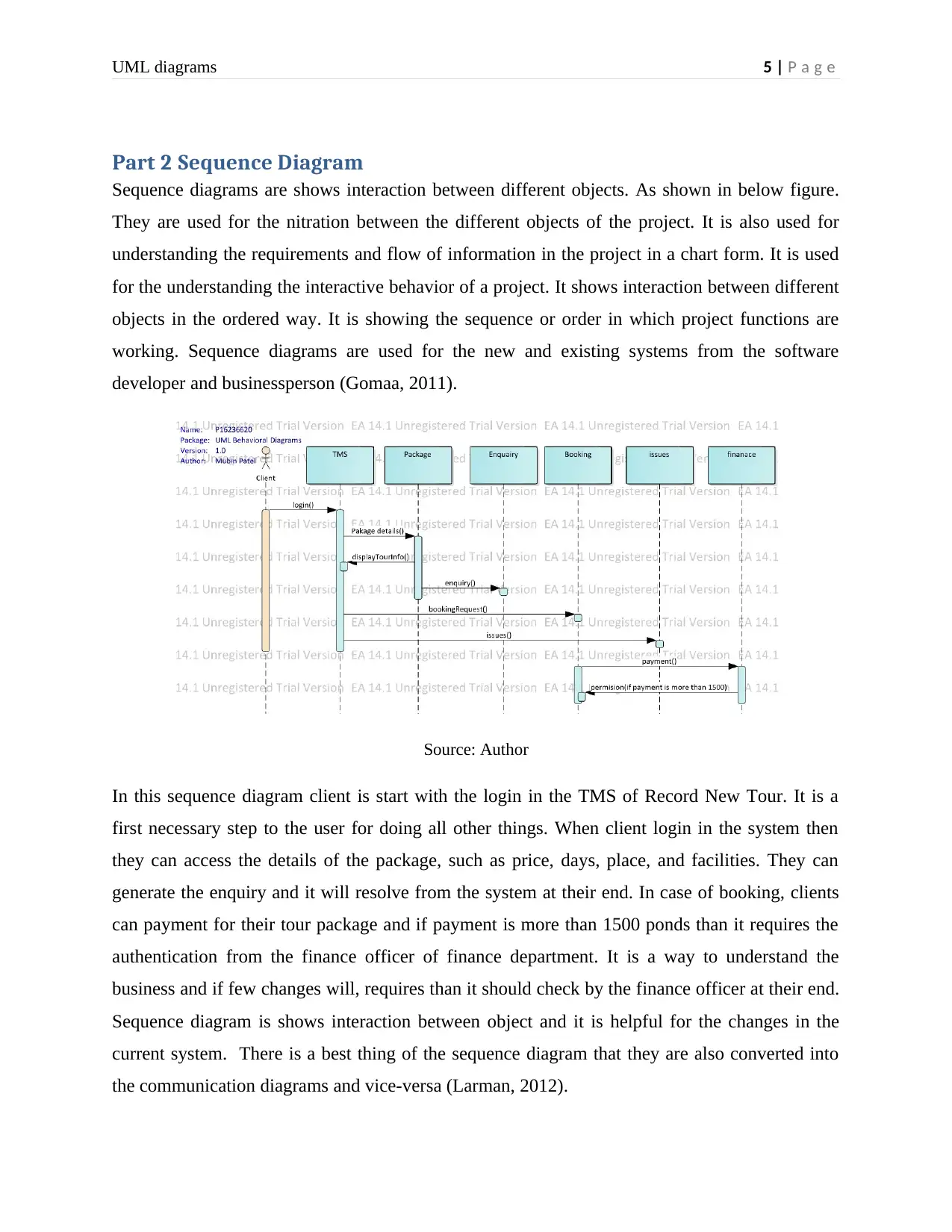
Sequence diagrams are shows interaction between different objects. As shown in below figure.
They are used for the nitration between the different objects of the project. It is also used for
understanding the requirements and flow of information in the project in a chart form. It is used
for the understanding the interactive behavior of a project. It shows interaction between different
objects in the ordered way. It is showing the sequence or order in which project functions are
working. Sequence diagrams are used for the new and existing systems from the software
developer and businessperson (Gomaa, 2011).
Source: Author
In this sequence diagram client is start with the login in the TMS of Record New Tour. It is a
first necessary step to the user for doing all other things. When client login in the system then
they can access the details of the package, such as price, days, place, and facilities. They can
generate the enquiry and it will resolve from the system at their end. In case of booking, clients
can payment for their tour package and if payment is more than 1500 ponds than it requires the
authentication from the finance officer of finance department. It is a way to understand the
business and if few changes will, requires than it should check by the finance officer at their end.
Sequence diagram is shows interaction between object and it is helpful for the changes in the
current system. There is a best thing of the sequence diagram that they are also converted into
the communication diagrams and vice-versa (Larman, 2012).
Part 2 Sequence Diagram
Sequence diagrams are shows interaction between different objects. As shown in below figure.
They are used for the nitration between the different objects of the project. It is also used for
understanding the requirements and flow of information in the project in a chart form. It is used
for the understanding the interactive behavior of a project. It shows interaction between different
objects in the ordered way. It is showing the sequence or order in which project functions are
working. Sequence diagrams are used for the new and existing systems from the software
developer and businessperson (Gomaa, 2011).
Source: Author
In this sequence diagram client is start with the login in the TMS of Record New Tour. It is a
first necessary step to the user for doing all other things. When client login in the system then
they can access the details of the package, such as price, days, place, and facilities. They can
generate the enquiry and it will resolve from the system at their end. In case of booking, clients
can payment for their tour package and if payment is more than 1500 ponds than it requires the
authentication from the finance officer of finance department. It is a way to understand the
business and if few changes will, requires than it should check by the finance officer at their end.
Sequence diagram is shows interaction between object and it is helpful for the changes in the
current system. There is a best thing of the sequence diagram that they are also converted into
the communication diagrams and vice-versa (Larman, 2012).
⊘ This is a preview!⊘
Do you want full access?
Subscribe today to unlock all pages.
Trusted by 1+ million students worldwide
UML diagrams 6 | P a g e
Part 3 Evaluation
Enterprise architecture (EA) tools are software program packages designed to helping client for
choosing the package according to the requirements. Different enterprises and IT stakeholders
with strategically pushed planning, evaluation, design and execution use it. EA equipment
support strategic and tactical decision making are using pictures and connecting context for
understanding the system. These diagrams are shows information across commercial enterprise,
such as statistics, generation domain names, at the side of other relevant architectural viewpoints.
The EA tool market includes a diverse range of carriers for managing the working of the system.
These software tools enable strategic for making plans that drives centered commercial
enterprise results ( Moné , 2018).
EA tools are beneficial for designing the diagrams of the system requirements. It is providing
brief information of the system in a proper way and it is a graphical way for the information.
This information is useful in the investment, improvement and delivery of IT solutions. EA is
mainly attention on software development, actionable, operational and enabling deliverables
things in the business that support commercial enterprises. EA tools help in the understanding of
the system with planning and executing commercial enterprise approach. In addition, they help
supply enterprise effects and mitigate issues in the system ( Oliver, 2017).
Sparx structures make the EA tools for a specialty of high performance. It is scalable visual
modeling equipment for the making plans, layout and construction of software development. EA
tools are helpful for the clients in industries, such as aerospace and car engineering. It is also
helpful in finance, defense, authorities, entertainment and telecommunications industries. EA
tools are working for different works. Sparx systems are a main supplier of innovative solutions
primarily based at the Unified Modeling Language. It is associated with the object control
organization (OMG). Sparx systems are committed to figuring out the capacity of version-driven
development based approaches, which are totally on open standards. Several enterprises are
having benefits form the EA tools. It was launched in August 2000. Enterprise Architect is
having the 580,000 registered clients for using their services ( Rouse, 2007).
I am using this tool for the creating different UML diagrams for understanding the system
requirements and it is also useful for the generating the code of that visualization of the
diagrams. In this EA tools, there are several functions for the creating the diagrams, model,
Paraphrase This Document
Need a fresh take? Get an instant paraphrase of this document with our AI Paraphraser
UML diagrams 7 | P a g e
processes. It is providing logical data model for the understanding the database working. It is
useful for creating charts and reports. It is also used for architect diagrams for enterprises. It is
having an integrated modeling platform for handling and creating the different diagrams for the
business and IT systems. Using EA tools, client can create different models for the analysis,
design, test, implementation, and maintenance using UML, BPMN, and different other open
standards. It is a multi-user tool for deigning robust and maintainable systems (SYSTEMS,
2000).
EA is providing high performance. It loads large models in the few seconds. It is having the
cloud-based servers, which are beneficial for distributed systems. It is also having simulation
facility for bring models to life. It is also provide controls to the client, such as username
password for accessing the simulation. It is also beneficial in the improving business outcomes.
Traceability is the best function of the EA tools. It is providing relationship matrix and Hierarchy
view. It is helping in the designing of the model, and it provides facility to manage and traces the
models. It provides use cases for understanding the working of the system. Few projects are
having large information about the system designing. It is so helpful for managing the
complexity of the models. EA case tool is best in the documentation. It generates the code in the
HTML on the single click. It provides source code in the different languages, such as C#, java,
python and many others.
Visualization of the EA tool is providing reverse engineering for the different software
development languages. It is also providing reusability of the code. It provides model driven
architecture for designing different models. Transformation of different template is the nice
function of EA tool. It is also supporting Model Driven Architecture (MDA).
EA tool is having debugging facility for the software development. It builds the code of the
architecture, tests that code, and run the deployment scripts. It is also supporting automation,
such as HTML reports for the internet on daily basis. EA tool is also supporting various
databases for helping the UML concepts, such as DB2, MySQL, Oracle, and many others. It
provides built in support for the different things, such as SysML, ADA 2005, and executable
code generation. It is also providing business process modeling. It uses UML for the base
modeling language. It is useful for business analysts, which are using activity diagrams, object
diagrams for understanding. It is beneficial for the project management.
UML diagrams 8 | P a g e
References
Florentine, . S., 2017. Why you need an enterprise architect. [Online]
Available at: https://www.cio.com/article/3197390/enterprise-architecture/why-you-need-an-
enterprise-architect.html
[Accessed 21 December 2018].
Moné , L., 2018. 9 Use Cases Solved With Enterprise Architecture: Part Two. [Online]
Available at: https://blog.leanix.net/en/9-use-cases-solved-with-enterprise-architecture-part-two
[Accessed 21 Deecember 2018].
Oliver, R., 2017. Why the Software Industry Has a Love-Hate Relationship with UML Diagrams.
[Online]
Available at: https://creately.com/blog/diagrams/advantages-and-disadvantages-of-uml/
[Accessed 17 November 2018].
Rouse, M., 2007. class diagram. [Online]
Available at: https://searchmicroservices.techtarget.com/definition/class-diagram
[Accessed 21 December 2018].
Bernstein, D., 2018. Analysis Class Diagrams. [Online]
Available at:
https://users.cs.jmu.edu/bernstdh/web/common/lectures/slides_analysis_class_diagrams.php
[Accessed 21 December 2018].
Bruegge, B. a. D. A., 2008. Object-Oriented Software Engineering Using UML, Patterns and
Java-(Required) (Vol. 2004).. 4 ed. London: Prentice Hall.
Conallen, J., 2012. Building Web applications with UML. 6 ed. New York: Addison-Wesley
Longman Publishing Co., Inc..
Dunstan Thomas, 2018. About Sparx Systems. [Online]
Available at: http://dthomas-software.co.uk/products/sparx-systems-enterprise-architect/
[Accessed 21 December 2018].
⊘ This is a preview!⊘
Do you want full access?
Subscribe today to unlock all pages.
Trusted by 1+ million students worldwide
UML diagrams 9 | P a g e
Gomaa, H., 2011. Software modeling and design: UML, use cases, patterns, and software
architectures. 2 ed. New York: Cambridge University Press.
Larman, C., 2012. Applying UML and patterns: an introduction to object oriented analysis and
design and interative development. 5 ed. New York: Pearson Education.
Siau, K. & Lee, L., 2004. Are use case and class diagrams complementary in requirements
analysis? An experimental study on use case and class diagrams in UML. Requirements
engineering, 9(4), pp. 229-237.
SYSTEMS, S., 2000. About Us. [Online]
Available at: https://sparxsystems.com/about.html
[Accessed 21 December 2018].
Van Lamsweerde, A., 2009. Requirements engineering: From system goals to UML models to
software. 2 ed. Chichester: John Wiley & Sons.
1 out of 10
Related Documents


Your All-in-One AI-Powered Toolkit for Academic Success.
+13062052269
info@desklib.com
Available 24*7 on WhatsApp / Email
![[object Object]](/_next/static/media/star-bottom.7253800d.svg)
Unlock your academic potential
Copyright © 2020–2026 A2Z Services. All Rights Reserved. Developed and managed by ZUCOL.