Competency Demonstration Report: Voltage Protection System Project
VerifiedAdded on 2019/10/31
|10
|1651
|304
Report
AI Summary
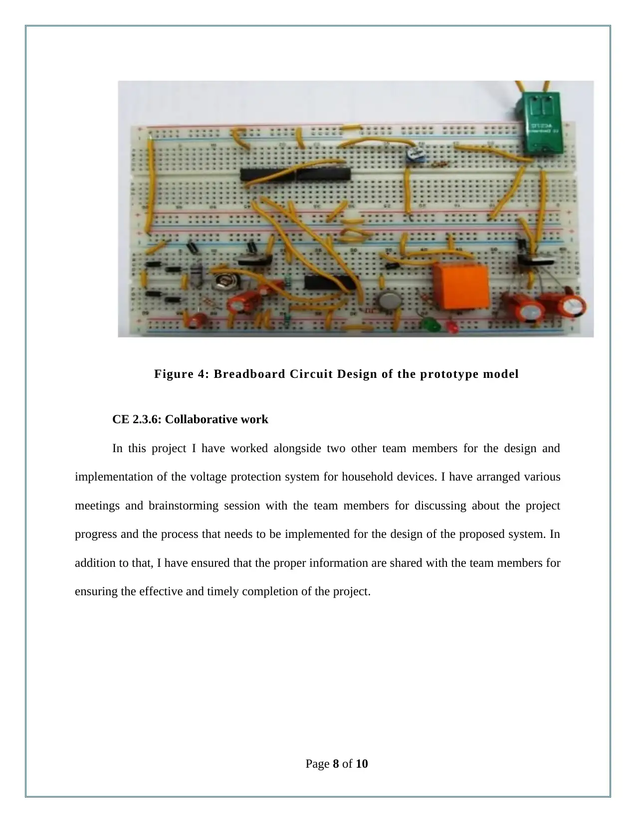
This report details a student's project focused on the design and implementation of an overvoltage and undervoltage protection system for household devices. The project involved understanding the underlying theory of voltage fluctuations and their impact on electrical appliances. The student designed a system using components like transistors, ICs (LM324 comparator, IC7408 microcontroller), and relays to detect and mitigate voltage surges and drops. The report covers the project's background, objectives, the student's role as a team member, the application of engineering knowledge in circuit design, and the challenges faced during implementation, such as potentiometer calibration issues. The student employed breadboard prototyping, manual testing, and potentiometer adjustments for system validation. The project aimed at creating a low-cost and reliable solution, making it suitable for household use. The report also highlights collaborative efforts, decision-making processes, and a comparison of this project with similar existing systems. The student successfully created a working prototype and tested it with household appliances. The project's key focus was on the practical application of electrical engineering principles to solve a real-world problem.

Competency Demonstration Report (CDR)
Career Episode 2
Career Episode 2
Paraphrase This Document
Need a fresh take? Get an instant paraphrase of this document with our AI Paraphraser

CE 2.1: Project Introduction
Name of the Project : Implementation of Overvoltage and Under voltage
Protection system
Geographical Location : [Please Fill]
Project Duration : [Please Fill]
Organization : [Please Fill]
Position in the Project : Team Member
CE 2.2: Project Background
CE 2.2.1: Characteristics of the Project
The increment in the “rotation per second” value of the voltage to a distinct level between
1.8 pu to 1.1. pu while the power frequency of the system remain between a minute to a half
cycle, the system experienced overvoltage condition. On the other hand, the under voltage
condition is illustrated with the decease of the value from the optimum level. I have learnt that
the sudden increase or decrease of the voltage in the power circuit results in the failure or
malfunction of the devices and the circuitry. I addition to that, both the over voltage and under
voltage condition often lead to loss of significant amount of data and information in computer
and various similar devices. I have found that it is most essential for the substation to engage in
the implementation of the voltage protection system for ensuring the reliability of the power.
During the study, I have observed that the transient overvoltage creates operational breakdown of
Page 1 of 10

both the industrial as well as household equipments. Therefore, in this project, I have worked for
the design and development of transient under voltage and over voltage detection system. In this
project I have used transistor, IC, comparator and other discrete devices.
CE 2.2.2: Objectives developed for project
In this project I have developed my significant aim to design and implement a low cost
and reliable voltage indicator and projection system both for household and commercial devices.
Through the proposed system, I have aimed at saving the electrical appliances from damage from
the sudden drop and rise of voltage. In this project, I have proposed for the simulation of the
proposed system with hardware. In addition to that, I have divided the project in smaller
divisions for better understanding and timely completion of the project. The detailed objectives
have been illustrated in the section below:
To identify the hardware components and materials required for the implementation
of the voltage protection system;
To evaluate the methods that will be used for implementing the system;
To design and print an appropriate circuit diagram for the development of the
required system;
To develop the prototype model for the voltage protection system;
To analyze the system for determining the appropriate functionality and operations;
CE 2.2.3: My area of work
In this project, in spite of working as team members for the completion of the design and
implementation of the voltage protection system, I have worked alongside the team members for
Page 2 of 10
⊘ This is a preview!⊘
Do you want full access?
Subscribe today to unlock all pages.

Trusted by 1+ million students worldwide

Head of Department
Assistant Teacher
Team Member (ME)
(
Team Member Team Member
developing the appropriate plan. In addition to that I have selected the appropriate electronics
elements and devices required for the proper functionality of the device.
CE 2.2.4: Project Group
Figure 1: Team Member Associated with the Project
CE 2.2.5: My responsibilities throughout the project
I took multifaceted responsibility during the progress time of this particular project. I
have discussed the project plan and procedure that needs to be followed for determining the
connectivity and operational functionality for the proposed voltage protection system. In addition
to that, I have developed the prototype model of the system with the use of bread board and
circuit obtained from the university laboratory.
CE 2.3: Distinctive Activity
CE 2.3.1: Comprehending the Theory of the project
Page 3 of 10
Paraphrase This Document
Need a fresh take? Get an instant paraphrase of this document with our AI Paraphraser

In his project, I have appropriately selected the hardware elements and components
required for developing a low cost voltage protection system. For the system implementation, I
have selected the application of transistor, IC, comparators and various discrete devices. I have
used LM324 comparator as a major component for controlling the performance of the device. In
the proposed system I have obtained the output with the 200 – 230 voltage for protecting the
household devices. I have further isolated the condition for voltage fluctuations with relay
tripping coil control with comparator. Through the comparator, I have compared the voltage with
the preset voltage for detecting the sudden surge. In addition to that, I have ensured that the coil
trips with supply voltage exceeding 5A. I have used IC7408 microcontroller for achieving under
voltage protection criterion.
Figure 2: Block Diagram developed for the proposed system
Page 4 of 10

CE 2.3.2: Engineering Knowledge and Skills applied in the project
In this project, I was mainly associated with the development of the circuit design and the
implementation of the prototype model of the voltage protector. For the circuit design, I have
connected the load with the integrated current supply when the current is observed below 5A
along with the voltage being more than 200 V. I have further integrated a down transformer for
stepping down the voltage in preferable and optimum voltage used by the household device. In
order to convert the AC to required DC voltage I have used 230/18V transformer with pulsation
and smoothening techniques (filter out). After the process of smoothening ad rectification, I have
fed the output through the potentiometer to the comparator. In addition to that, I have used the
relay driver along with transistor. I have determined the transistor’s current gain with the
following equation:
β = IC / IB
In the above equation, I have used β as current gain, IB as the base current and IC as the
collector current.
Page 5 of 10
⊘ This is a preview!⊘
Do you want full access?
Subscribe today to unlock all pages.

Trusted by 1+ million students worldwide

Figure 3: Circuit Diagram of the proposed System
CE 2.3.3: Accomplishment and Task Performed
I have identified the various hardware components and elements that required for the
implementation of the voltage protection system. I have evaluated and studied various elements
available in the market and selected the appropriate elements require for the low development
cost of the system.
CE 2.3.4: Identified Issues and Their Solutions
Issue: I have engaged myself during the design of the circuit diagram for the proposed
voltage protection system. I have faced significant issue with the practical implementation of the
circuit on the bread board. The main issue that slowed down the project progress was the error in
the potentiometer calibration for detecting the value of the voltage through the circuit.
Solution: In order to overcome with the issue, I have discussed the matter with the
assistant teacher involved in this project. Upon this guidance I have provided 12 V input of DC
Page 6 of 10
Paraphrase This Document
Need a fresh take? Get an instant paraphrase of this document with our AI Paraphraser

current. Furthermore, I have used led light for the identification of the voltage condition. I have
programmed the system in such a way that green light was switched on when normal operation
was detected and red light was switched on when under or over voltage operation was detected.
CE 2.3.5: Plan for producing creative and innovative work
I have conducted the test for the operations and functionality of the proposed voltage
protections system. For providing innovative work, I have carried out both the manual testing
and the potentiometer calibration. Through the application of the manual testing I have ensured
the proper functionality and operation of LM324 comparator. In addition to that, I have utilized
the potentiometer for adjusting and dividing the voltage to an optimum safe level. Further, I have
set a threshold to the potentiometer for tripping the variac used in the relay. In addition to that, I
have used home alliances including refrigerator and television for testing the functionality and
operation of the developed prototype model.
Page 7 of 10

Figure 4: Breadboard Circuit Design of the prototype model
CE 2.3.6: Collaborative work
In this project I have worked alongside two other team members for the design and
implementation of the voltage protection system for household devices. I have arranged various
meetings and brainstorming session with the team members for discussing about the project
progress and the process that needs to be implemented for the design of the proposed system. In
addition to that, I have ensured that the proper information are shared with the team members for
ensuring the effective and timely completion of the project.
Page 8 of 10
⊘ This is a preview!⊘
Do you want full access?
Subscribe today to unlock all pages.

Trusted by 1+ million students worldwide

CE 2.4: Project Review
CE 2.4.1: Decision Making Process
Before engaging in the implementation of the voltage protector system, I have gone
through various articles and journals understanding the working of the voltage protector and over
and under voltage condition. I have therefore divided the project in to two major divisions. In
the initial division I have worked for the determination of the voltage. And on the second
division, I have worked for controlling the voltage with the design and implementation of the
protection system.
CE 2.4.2: Comparatively Better In This Project Among Other Similar Projects
Voltage determination and protection system exists in the market but are mostly used in
the industrial factories due to high cost and complexity of use. In this project, I have used
hardware electrical components and design considering low cost and effective application in this
project. I have further used the components that can be easily available in the market that has
resulted in the low cost system development that can be used with the household devices.
Page 9 of 10
1 out of 10
Related Documents

Your All-in-One AI-Powered Toolkit for Academic Success.
+13062052269
info@desklib.com
Available 24*7 on WhatsApp / Email
Unlock your academic potential
Copyright © 2020–2025 A2Z Services. All Rights Reserved. Developed and managed by ZUCOL.