Project Report: Indoor Building Solution Design through Matlab
VerifiedAdded on 2021/06/15
|75
|12224
|65
Project
AI Summary
This project report, submitted by Sami Mohammed Fadhil Al Aamri to Middle East College, details the design and implementation of an Indoor Building Solution (IBS) using Matlab. The project focuses on enhancing indoor mobile coverage, addressing challenges like signal obstruction and interference. It explores Distributed Antenna Systems (DAS) to optimize user capacity and quality of service, considering both passive and active DAS architectures. The report includes system modeling, link budget calculations, and simulations to analyze antenna performance and RF coverage. It also covers project objectives, limitations, methodology, literature review, budgeting, design, analysis, simulation, testing, and implementation aspects. The project culminates in a critical evaluation, legal, social, ethical and sustainability aspects, conclusions, and recommendations for improved IBS design in urban settings. The report provides detailed calculations, diagrams, and simulation results to demonstrate the effectiveness of the proposed IBS solution.
A PROJECT DESIGN & IMPLEMENTATION REPORT
ON
(Indoor Building Solution (IBS) design through
Matlab)
By
(Sami Mohammed Fadhil Al Aamri, 14F12846)
Guided by
(Dr. Nizar Al Bassam)
A Project report submitted in partial fulfillment of the requirements for the
award of
Bachelors in Electronics and Telecommunication Engineering
MIDDLE EAST COLLEGE
Knowledge Oasis Muscat, Muscat, Oman
July, 2018
Paraphrase This Document
Need a fresh take? Get an instant paraphrase of this document with our AI Paraphraser
A PROJECT DESIGN & IMPLEMENTATION REPORT
ON
(Indoor Building Solution (IBS) design through
Matlab)
By
(Sami Mohammed Fadhil Al Aamri, 14F12846)
July, 2018
ii
ON
(Indoor Building Solution (IBS) design through
Matlab)
By
(Sami Mohammed Fadhil Al Aamri, 14F12846)
July, 2018
ii
DECLARATION
I, “Sami Mohammed Fadhil Al Aamri”, hereby declare that the work presented herein is
genuine and has not been copied in part or in whole from any other source except where
duly acknowledged. As such, all use of previously published work (from books, journals,
magazines, internet, etc.) has been acknowledged within the main report to an item in the
references or bibliography lists.
Copyright Acknowledgement
I acknowledge that the copyright of this project and report belongs to MEC.
Student Name Student ID Signature
Sami Mohammed Fadhil Al Aamri 14F12846
iii
⊘ This is a preview!⊘
Do you want full access?
Subscribe today to unlock all pages.
Trusted by 1+ million students worldwide
APPROVAL FORM
The project planning report entitled PROJECT Indoor Building Solution (IBS) design
through Matlab __________________ submitted by Sami Mohammed Fadhil Al
Aamri (ID. 14F12846.)______________________ is approved in partial fulfillment of
the requirements for degree of Bachelors of Engineering in Electronics and
Telecommunication.
_________________________
Supervisor
Full name: Dr. Nizar Al Bassam
Department: Electronics and Telecommunication Engineering
Date:
_______________________
Examiner
Full name:
Department:
Date:
iv
Paraphrase This Document
Need a fresh take? Get an instant paraphrase of this document with our AI Paraphraser
ACKNOWLEDGEMENT
I would like to appreciate and thanks Mr. Nizar Al Bassam for his support and help
during this period of planning stage. He guides me too much how to get the idea, how to
prepare the report, which books can be support my project& which internet source can be
support my project.
Also he is checking the format of report and each part which I wrote, always I
appreciated his time and patience as I have asked so many questions/ query. Also I would
thank Department of Electronics & Communication Engineering for supply the sources
which I required for this project (books, software).
v
ABSTRACT
This thesis discusses the In-building solutions which are implemented using the
IBS distributed antenna systems. These systems have been utilized in different sections
and proven to be quite efficient in optimizing the user capacity and quality of service for
a licensed spectrum. The implementation of the solution reduces the need for cabling and
power used during the transmission from one central antenna. RF coverage within
buildings is growing rapidly in telecom market in recent years. Demand for the wireless
users increased seemingly and now reliable communication is required in the offices and
residential buildings as per their business and personal requirements. Distributed Antenna
System (DAS) is used for the extension of and enhancement of mobile network coverage.
DAS is the topic of this thesis, the aim of which is to enhance DAS solutions for indoor
sites to improve the efficiency and maintaining the required Quality-of-Service (QoS).
Consider the radio part, it is indicating that by changing the antenna positions
with the help of simulation, efficiency can be improved. Ultimately, it appears that, both
radio and optical components, there is a higher limit of efficiency, that is, there is usually
the optimal number of antennas that provide the best results and consistent service quality
for the system. The objective of this project is to provide advanced coverage for the
buildings using different parameters selection and algorithm techniques. It will show the
real-time coverage for the proposed indoor antennas which will be connected through
different splitters and couplers using feeder cables. Gains and losses for each device will
be defined in MATLAB system to calculate link budget and EIRP (Effective Isotropic
Radiated Power) for the antennas. (Anon, 2018)
vi
⊘ This is a preview!⊘
Do you want full access?
Subscribe today to unlock all pages.
Trusted by 1+ million students worldwide
TABLE OF CONTENTS
DECLARATION......................................................................................................................iii
APPROVAL FORM..................................................................................................................iv
ACKNOWLEDGEMENT..........................................................................................................v
ABSTRACT..............................................................................................................................vi
TABLE OF CONTENTS.........................................................................................................vii
LIST OF FIGURES....................................................................................................................x
LIST OF TABLES......................................................................................................................x
LIST OF ABBREVIATIONS....................................................................................................xi
1. INTRODUCTION................................................................................................................12
1.1 Background of the Project.....................................................................12
1.2 Project Objectives.................................................................................13
1.3 Project Limitations................................................................................13
1.4 Overview of the Project Report.............................................................14
1.5 Chapter # 1: Introduction to DAS.........................................................16
1.5.1 Distributed Antenna System (DAS)........................................................16
1.5.2 Passive Distributed Antenna System.....................................................16
1.5.3 Passive DAS Architecture.....................................................................16
1.5.4 Active Distributed Antenna System......................................................18
1.5.5 Active DAS Architecture......................................................................18
1.5.5 DAS Architecture studied in the thesis..................................................20
1.6 Chapter # 2: DAS Modeling System.....................................................21
1.6.1 Characteristics of Components.........................................................................................21
1.6.2 Link Budget..........................................................................................24
2. METHODOLOGY...............................................................................................................25
vii
Paraphrase This Document
Need a fresh take? Get an instant paraphrase of this document with our AI Paraphraser
..................................................................................................................................................25
3. LITERATURE REVIEW/THEORY....................................................................................26
4. BUDGETING AND PROJECT MANAGEMENT...............................................................35
4.1 Project Budget......................................................................................35
4.2 Project Schedule...................................................................................35
4.3 Risk Management.................................................................................36
5. DESIGN AND ANALYSIS..................................................................................................36
5.1 System Initial Design............................................................................36
5.2 Technical Requirements........................................................................37
5.3 Schematic Diagram.............................................................................................................39
5.4 System Design & Analysis.................................................................................................39
5.4.1 In-Building Distributed Antenna System Design...................................39
5.4.2 Calculations for the Basic Path Loss......................................................40
5.4.3 Prediction of Received Signal Strength.................................................41
5.4.4 Noise Factor..........................................................................................42
5.4.5 Interference...........................................................................................42
6. SIMULATION, TESTING AND IMPLEMENTATION.....................................................47
6.1 System Simulation..............................................................................................................47
6.2 System Testing....................................................................................................................56
6.3 System Implementation/Prototyping...................................................................................61
7.CRITICAL EVALUATION..................................................................................................62
9.Legal, social, ethical and sustainability aspects related to the project....................................64
9. CONCLUSIONS AND RECOMMENDATIONS................................................................66
REFERENCES.........................................................................................................................68
Appendix A..............................................................................................................................70
viii
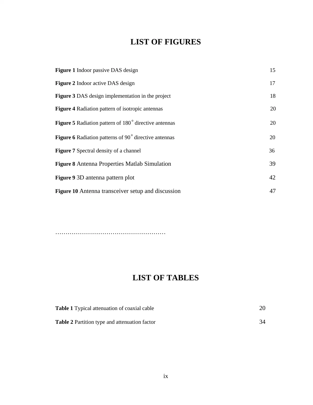
LIST OF FIGURES
Figure 1 Indoor passive DAS design 15
Figure 2 Indoor active DAS design 17
Figure 3 DAS design implementation in the project 18
Figure 4 Radiation pattern of isotropic antennas 20
Figure 5 Radiation pattern of 180 o directive antennas 20
Figure 6 Radiation patterns of 90 o directive antennas 20
Figure 7 Spectral density of a channel 36
Figure 8 Antenna Properties Matlab Simulation 39
Figure 9 3D antenna pattern plot 42
Figure 10 Antenna transceiver setup and discussion 47
………………………………………………
LIST OF TABLES
Table 1 Typical attenuation of coaxial cable 20
Table 2 Partition type and attenuation factor 34
ix
⊘ This is a preview!⊘
Do you want full access?
Subscribe today to unlock all pages.
Trusted by 1+ million students worldwide
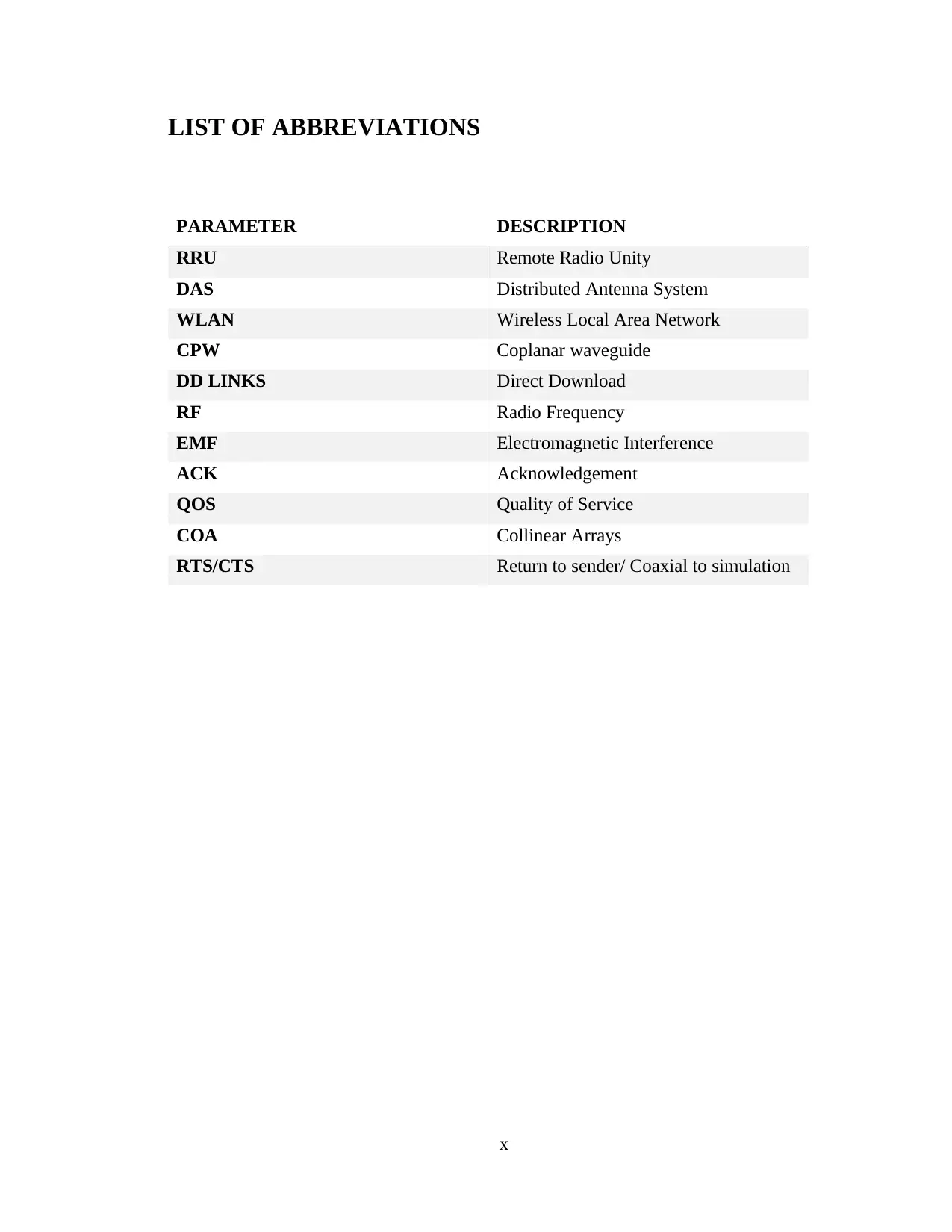
LIST OF ABBREVIATIONS
PARAMETER DESCRIPTION
RRU Remote Radio Unity
DAS Distributed Antenna System
WLAN Wireless Local Area Network
CPW Coplanar waveguide
DD LINKS Direct Download
RF Radio Frequency
EMF Electromagnetic Interference
ACK Acknowledgement
QOS Quality of Service
COA Collinear Arrays
RTS/CTS Return to sender/ Coaxial to simulation
x
Paraphrase This Document
Need a fresh take? Get an instant paraphrase of this document with our AI Paraphraser
1. INTRODUCTION
With the advent of different technologies, the mobile devices have become the
most preferred means of communication. It is easier to work with as it provides for
mobility and gives the users a platform to access the internet and other online systems
from any geographical location. The in-building coverage is required as there is a lot of
obstruction caused by the concrete walls and other equipment. For instance, when a user
tries to receive a phone call while in the lift, it is usually a big problem. The lifts are
usually situated at the middle of the building meaning they encounter a lot of interference
or obstruction. This is the biggest problem with the mobile coverage especially if the
telecommunication service provider antenna is located a distance away from the building.
Statistics show that up to 70 percent of the mobile users or the mobile traffic is recorded
for the people who are inside the buildings and the remaining 30 percent is for the people
who are outside or on the streets. The wide area networks in a region are ubiquitous. The
shift in operator’s network build-out is emphasized especially in the 2G, 3G, and small
cell networks where there is a higher user density. The large buildings in the urban areas
host a large number of people who are there for work or for other recreational activities
are required (Tolstrup, 2011).
1.1 Background of the Project
The demand for higher data rate services at any given time in any location has
increase to very high levels. The wireless network data usage demand is expected to
rise even higher as the mobile gadget are becoming more and more accessible to
more people globally. There are several approaches taken to achieve higher data
rates since the number of connected user devices keeps rising exponentially over the
years. The designers can opt to provide more spectrum using carrier aggregation,
heterogenous network, and multi-tier network. The cooperative strategy is used for
client cooperation and network MIMO with higher dimensional system where the
distributed antenna systems and higher order MIMO systems are implemented. The
mobile antenna networks are usually preferred over the Wi-Fi services mainly
because of the coverage. The antennas tend to over distances in terms of kilometers
while still providing quality connectivity. There is coherent coverage and the new
mobile users can integrate or get access by using laptops with mobile card
11
integration (Ahlin, et al., 2006). There is less cost for every data rate bundle procured
and there is no need to obtain the scratch cards used by the Wi-Fi service providers.
There is also seamless billing with the mobile phones. The data speeds can be easily
compares with those of the Wi-Fi. One of the major limitations of the mobile
networks is the ADSL backhaul and not the radio interface of the Wi-Fi AP. The 3G
and LTE networks provide faster user speeds for the mobile users (Shabbir & Kashif,
2009). The trend in the technological advances and in the use of mobile equipment is
focused on the use of data to manage the voice, multimedia, and data over the mobile
networks. The speeds are very high as the telecommunication service providers link
the microwave links to the fiber links to ensure fast speeds (Josse, et al., 2011).
Based on this research, limits for human exposure to RF fields have been set by
scientific organizations (Tolstrup, 2011).
1.2 Project Objectives
To provide better mobile coverage for indoor users in urban setting building by
implementing the best indoor solution parameters and algorithm techniques.
To perform the real-time coverage of all sections of the building to improve
performance using antenna and feeder cables.
1.3 Project Limitations
(i) Some of the issues that arise when such systems are implemented
in building include licensing, clearance from building owners and
interference from other systems.
(ii) Another common caveat to the installation of IBS in sky scrapers
is that the building receives signals from more than one base
station which causes a massive interference. The metallic coated
windows attenuate the signals and this causes degraded or no
service as well as dropped calls. The solution should focus on
having a dominant signal serve the building to minimize the
interference to negligible values.
12
⊘ This is a preview!⊘
Do you want full access?
Subscribe today to unlock all pages.
Trusted by 1+ million students worldwide
1 out of 75


Your All-in-One AI-Powered Toolkit for Academic Success.
+13062052269
info@desklib.com
Available 24*7 on WhatsApp / Email
![[object Object]](/_next/static/media/star-bottom.7253800d.svg)
Unlock your academic potential
Copyright © 2020–2026 A2Z Services. All Rights Reserved. Developed and managed by ZUCOL.