Research Report: Recent Control Strategies for Induction Motor Drives
VerifiedAdded on 2022/10/17
|10
|2298
|14
Report
AI Summary
This report addresses key aspects of electrical machines and drives, focusing on induction motor control strategies. It begins by explaining the purposes and types of transformers used in electrical systems, providing examples for industrial applications. The report then details the structural differences between induction and synchronous machines, highlighting their applications. It explains the common use of induction machines as motors and synchronous machines as generators, providing justifications for each. The core of the report is a discussion of recent control strategies for induction motor drives, supported by research and industrial applications. The report also includes discussions on the working principles, advantages, and disadvantages of synchronous and induction machines, and their respective roles in power generation and motor applications. The content covers topics such as stator and rotor design, synchronous generators, reactive power, and the benefits of synchronous generators in power supply. The report is based on research from academic and industrial resources, offering a comprehensive analysis of the subject.

RECENT CONTROL STRATEGIES FOR INDUCTION MOTOR DRIVE
By Name
Course
Instructor
Institution
Location
Date
By Name
Course
Instructor
Institution
Location
Date
Paraphrase This Document
Need a fresh take? Get an instant paraphrase of this document with our AI Paraphraser
Purposes of using transformers in electrical systems
Transformers also known as voltage transformers are gadgets that are used in electrical circuits
in changing electricity voltage that flows in a circuit. Transformers may either be used in
increasing or decreasing the voltage also known stepping up or stepping down voltage.
Energy tends to get lost during transmission of electricity over long distances for instance during
the move from a power plant to the final consumption. Less energy gets lost in case voltage is
high hence electrical utilities utilize high voltage in transmission over long distance wires. The
voltage is however quite dangerous for use in homes. Electrical utilities adopt transformers in
changing the voltage of electricity as it moves from the power plant to final destination
consumption. The voltage coming from power plant is then stepped with use of transformers to
required levels for transmission over long distance. At a later stage, voltage undergoes stepping
down prior to its entry to the final consumption point, still using transformers.
For proper functioning of electrical power distribution network, there has to be stepping up of
voltages prior to transmission of power over longer distances over power lines. One great
challenge is that there is loss of power between the consumers and power plants since some of
power are used by current in heating transmission lines. The power that is transmitted along line
is equivalent to the voltage multiplied by current. When the voltage is higher current has to be
lower within transmission lines to generate same amount of power. Lower currents generate
relatively less heating as well as less loss of power. The high voltages of course have to be
stepped back down prior to supply of power to the final consumption points. Transformers thus
tend to be of utmost importance in stepping and stepping down voltages at every end of line.
Types of transformers
Based on usage
These are grouped as power, protection as well as distribution transformers alongside measuring
transformers.
Power transformers are enormous in size and are suitable for power transfer applications that
transfer at high voltages. It is often used in generation stations of power as well as transmission
power stations. It comes along with high levels of insulation.
Distributing Transformer: These transformers are used in the distribution of power produced
from the power production plant to the remote regions. It is basically used in the distribution of
electrical energy at relatively lower voltages that are less than 33kV in the industrial application
and 440V-220V for domestic uses (Zhang, Yang & Xia, 2016). The major features include:
Working at efficiencies in the range of 50 to 70%
Easy to install
Have low magnetic losses
Small in size
Not often fully loaded
Measurement transformer: Adopted in measuring the quality of electricity for instance current,
power voltage among others. These are grouped as current transformers, potential transformers
among others.
Protection transformers: These are adopted in component protection purpose. The main
difference between protection transformers and measuring transformers is level of accuracy
⊘ This is a preview!⊘
Do you want full access?
Subscribe today to unlock all pages.

Trusted by 1+ million students worldwide
meaning the protection transformers ought to be more accurate in comparison with measuring
transformers.
The main structural difference between induction & synchronous machines
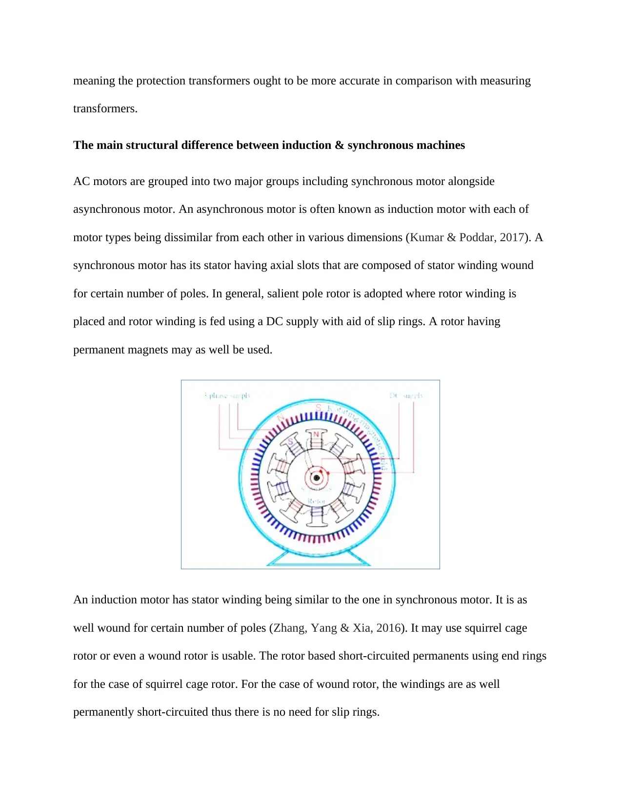
AC motors are grouped into two major groups including synchronous motor alongside
asynchronous motor. An asynchronous motor is often known as induction motor with each of
motor types being dissimilar from each other in various dimensions (Kumar & Poddar, 2017). A
synchronous motor has its stator having axial slots that are composed of stator winding wound
for certain number of poles. In general, salient pole rotor is adopted where rotor winding is
placed and rotor winding is fed using a DC supply with aid of slip rings. A rotor having
permanent magnets may as well be used.
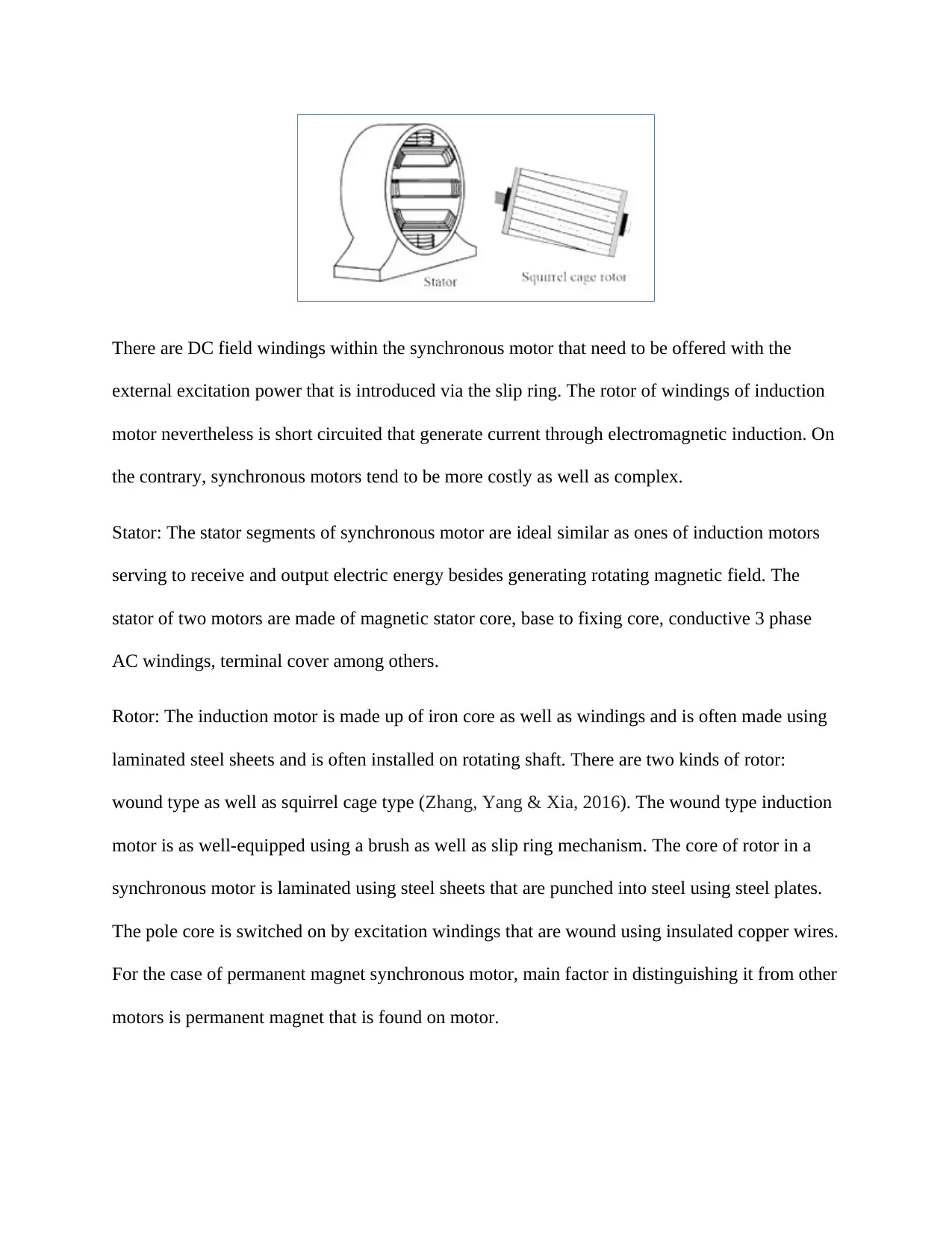
An induction motor has stator winding being similar to the one in synchronous motor. It is as
well wound for certain number of poles (Zhang, Yang & Xia, 2016). It may use squirrel cage
rotor or even a wound rotor is usable. The rotor based short-circuited permanents using end rings
for the case of squirrel cage rotor. For the case of wound rotor, the windings are as well
permanently short-circuited thus there is no need for slip rings.
Paraphrase This Document
Need a fresh take? Get an instant paraphrase of this document with our AI Paraphraser
There are DC field windings within the synchronous motor that need to be offered with the
external excitation power that is introduced via the slip ring. The rotor of windings of induction
motor nevertheless is short circuited that generate current through electromagnetic induction. On
the contrary, synchronous motors tend to be more costly as well as complex.
Stator: The stator segments of synchronous motor are ideal similar as ones of induction motors
serving to receive and output electric energy besides generating rotating magnetic field. The
stator of two motors are made of magnetic stator core, base to fixing core, conductive 3 phase
AC windings, terminal cover among others.
Rotor: The induction motor is made up of iron core as well as windings and is often made using
laminated steel sheets and is often installed on rotating shaft. There are two kinds of rotor:
wound type as well as squirrel cage type (Zhang, Yang & Xia, 2016). The wound type induction
motor is as well-equipped using a brush as well as slip ring mechanism. The core of rotor in a
synchronous motor is laminated using steel sheets that are punched into steel using steel plates.
The pole core is switched on by excitation windings that are wound using insulated copper wires.
For the case of permanent magnet synchronous motor, main factor in distinguishing it from other
motors is permanent magnet that is found on motor.
The working of a synchronous generator is dependent on Faraday’s law of electromagnetic
induction, operating in same fashion as automotive type alternator. The difference in this case is
that synchronous generator produces three phase AC output of voltage from stator windings as
opposed to DC generator that generates single DC or even direct current output. Single phase
synchronous generators are as well available for low power domestic wind turbine synchronous
systems of generators.
The synchronous motor is a synchronous electro-mechanical machine utilized in form of
generator and is composed of a magnetic field on rotor which rotates alongside a stationary stator
composed of numerous windings which supplies produced power. The rotors magnetic field is
generated through the use of either permanent magnets directly onto rotor or even energized in
electromagnetic manner by the use of an external DC current that flows in windings of rotor
field.
The DC field current moves to rotor of synchronous machine through slip rings as well as carbon
or graphite brushes. As opposed to previous DC generator design, synchronous generators do not
need sophisticated commutation enabling for simple as well as easy construction. The
synchronous generator works in the same way to automotive car alternators and is made up of
stator alongside rotor.
When discussing synchronous generators or inductors, term is used in providing description to
parts of machines. The field windings refer to the windings generating main magnetic field that
are windings of rotor for synchronous machine as well as armature that are windings in which
main voltage tends to be induced.
⊘ This is a preview!⊘
Do you want full access?
Subscribe today to unlock all pages.

Trusted by 1+ million students worldwide
There are some reasons as to why synchronous generators are utilized in the supply of electric
power including:
Constant voltage
Ability to deliver alongside reactive power
Constant frequency
Adequate synchronization among all alternators to a definite bus bar
Different generators from the entire world synchronize with such infinite bus that is able to
supply electric power from any point globally (Zhang, Yang & Xia, 2016). This comes along
with flexibility to enhance the number of producing units that are synchronized with the infinite
bus bar. When induction generators are used in place of synchronous generators on another hand,
two aspects would be presented:
Reactive power needs of IG
Harmonic content in the power spectrum output
The IG needs reactive power for it to operate that should be provided be it by capacitor banks or
even IG units had to be connected to a stable grid in which relative power is availed. Suppose IG
is used in electric power production, there will be severe active as well reactive issues with
power and thus voltage will have some imbalance (Duran & Barrero, 2015). Suppose there is
need to install capacitor banks, huge costing will be incurred in installation of such equipment.
The output frequency of an induction generator varies that will generate uncertainties in making
decision in ratings for electric equipment as well as load side equipment will have challenges
with varying frequency. Handling this would require changing variable AC power to DC power
and back to fixed frequency AC power with the use of electronic equipment that induces high
Paraphrase This Document
Need a fresh take? Get an instant paraphrase of this document with our AI Paraphraser
contents of harmonics in the output spectrum that is not desirable alongside the design of
harmonic filters and implementation that would enhance cost. Synchronous generators hence are
used in the supply of power that is majorly large generation units for instance thermal, nuclear,
and hydro as well as gas power plants.
Induction machines are commonly used as motor
There is need to offer double excitation to generate a rotation in a DC motor. A single supply is
provided to the stator while anoyher is given to the rotor via brush arrangement in DC motor. For
the case of induction motor, just a single supply is given hence interest in gained in
understanding the working of an induction motor. Just as name suggests it is possible to gain an
understanding of induction process that takes place (Duran et al., 2015). When the supply is
given to stator winding, there is production of a magnetic flux within the stator as a result of
current flow within the coil. The arrangement of rotor winding is done in such a way that every
coil tends to be short-circuited.
The flux produced from stator tends to cut short circuit within the rotor and since the rotor coils
are short-circuited as per Faraday’s law of electromagnetic induction, the current would begin
flowing via the coil of rotor. There are two fluxes generated: rotor flux and stator flux. The rotor
flux would tend to be lagging in comparison with stator flux and as a result the rotor will having
a torque feeling that will render the rotor to undergo rotation in the same direction as rotating
magnetic field (Habibullah et al., 2016). This serves as principle of operation of both three and
single phase induction motors.
Induction motors are used as motor as a result of their robust nature in design, low efficiency as
well as low cost of maintenance. They are used in categorical applications as they are not able to
generate reactive power. On the other hand synchronous generators are able to generate both
reactive as well as active power and going by the load demand, the two powers are needed thus
induction generator are not normally used as generators (Kumar & Poddar, 2017). The
fundamental burden of an acceptance engine is that the speed of the engine changes with the
applied burden. The bearing of revolution of enlistment engine can without much of a stretch be
changed by changing the stage grouping of three-stage supply, i.e., if RYB is a forward way, the
RBY will make the engine to turn backward heading. This is on account of three stage engine,
however in a solitary stage engine; the bearing can be turned around by switching the capacitor
terminals in the winding
⊘ This is a preview!⊘
Do you want full access?
Subscribe today to unlock all pages.

Trusted by 1+ million students worldwide
References
Duran, M. J., & Barrero, F. (2015). Recent advances in the design, modeling, and control of
multiphase machines—Part II. IEEE Transactions on Industrial Electronics, 63(1), 459-
468
Duran, M. J., Prieto, I. G., Bermudez, M., Barrero, F., Guzman, H., & Arahal, M. R. (2015).
Optimal fault-tolerant control of six-phase induction motor drives with parallel
converters. IEEE transactions on industrial electronics, 63(1), 629-640
Habibullah, M., Lu, D. D. C., Xiao, D., & Rahman, M. F. (2016). A simplified finite-state
predictive direct torque control for induction motor drive. IEEE Transactions on
Industrial Electronics, 63(6), 3964-3975
Kumar, Y. S., & Poddar, G. (2017). Medium-voltage vector control induction motor drive at zero
frequency using modular multilevel converter. IEEE Transactions on Industrial
Electronics, 65(1), 125-132
Zhang, Y., Yang, H., & Xia, B. (2016). Model-predictive control of induction motor drives:
Torque control versus flux control. IEEE Transactions on Industry Applications, 52(5),
4050-4060
1 out of 10
Related Documents
Your All-in-One AI-Powered Toolkit for Academic Success.
+13062052269
info@desklib.com
Available 24*7 on WhatsApp / Email
![[object Object]](/_next/static/media/star-bottom.7253800d.svg)
Unlock your academic potential
Copyright © 2020–2025 A2Z Services. All Rights Reserved. Developed and managed by ZUCOL.


