Industrial Automation System: Components and Architecture Analysis
VerifiedAdded on 2021/11/10
|8
|1541
|228
Report
AI Summary
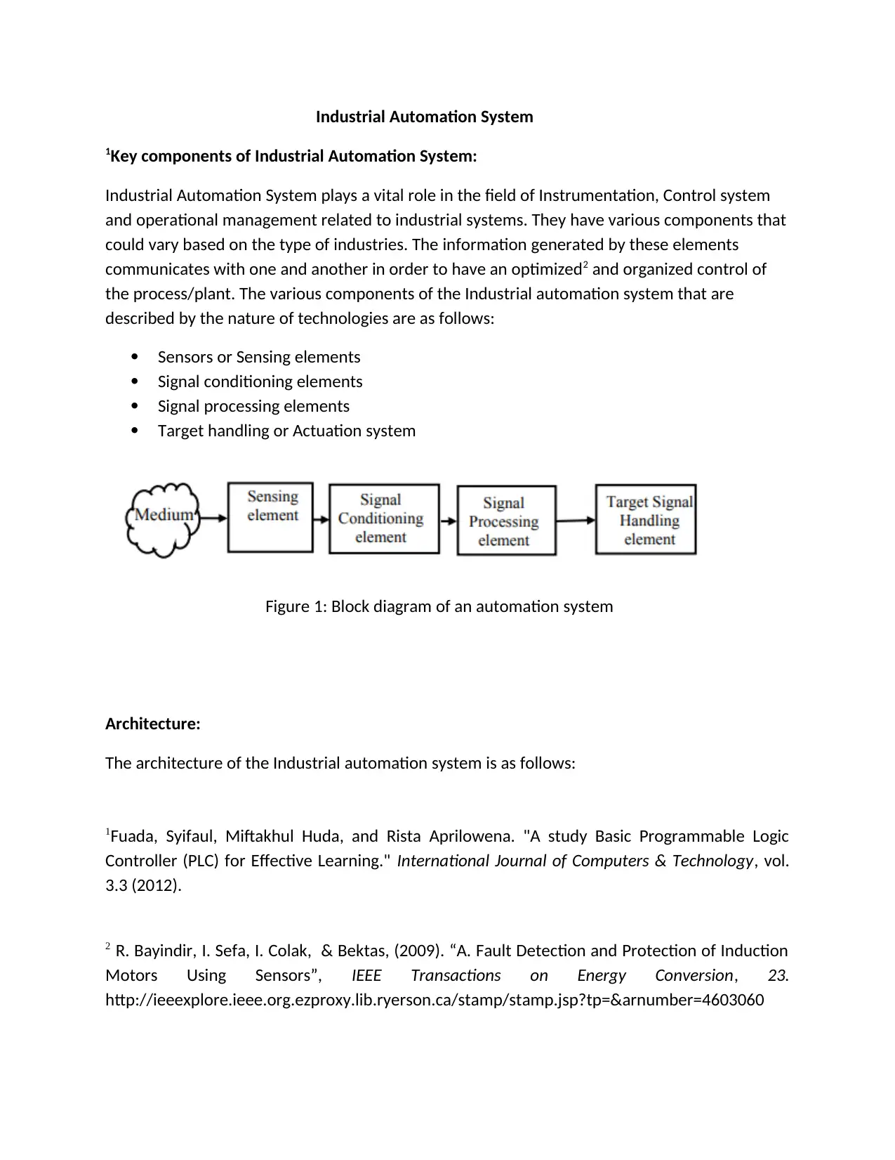
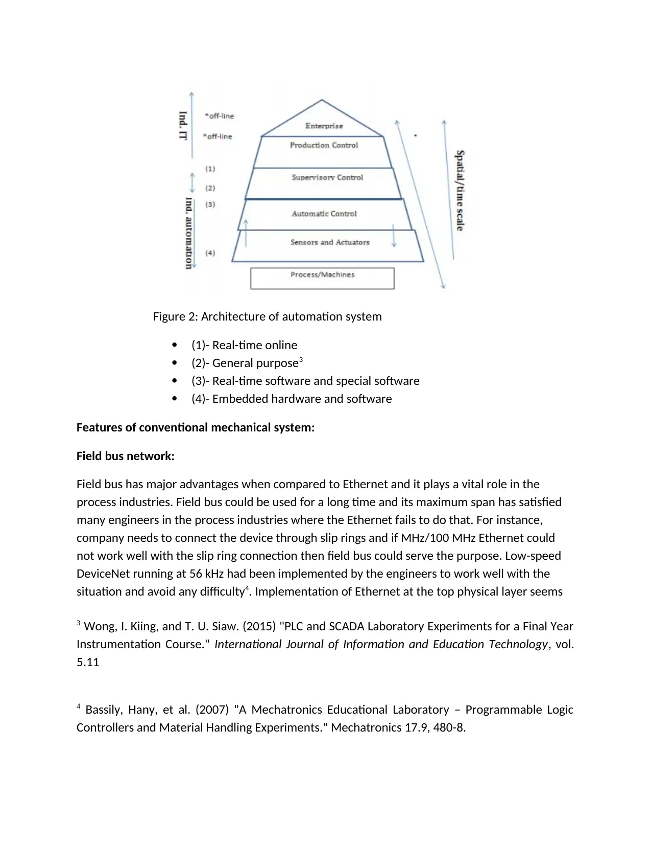
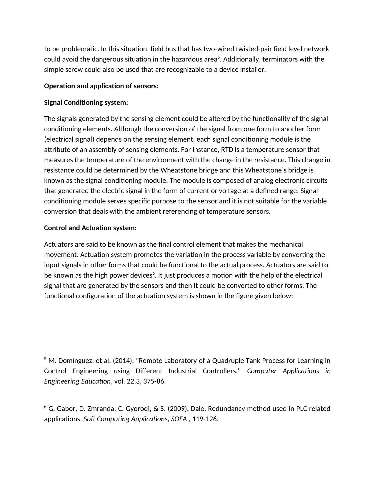
This report provides a detailed analysis of industrial automation systems, focusing on their key components and architecture. It explores the roles of sensors, signal conditioning elements, and actuation systems in controlling industrial processes. The report delves into the architecture of automation systems, differentiating between real-time online, general-purpose, and embedded systems. It further examines the application of fieldbus networks, sensors in mechatronics, and the operational principles of pneumatic and hydraulic power systems. The report highlights the significance of Programmable Logic Controllers (PLCs) and Supervisory Control and Data Acquisition (SCADA) systems in industrial automation. Moreover, it includes a discussion on the functional configuration of actuation systems and the components involved in pressure control loops. Finally, it includes a comprehensive bibliography of relevant research papers.
Contribute Materials
Your contribution can guide someone’s learning journey. Share your
documents today.

Industrial Automation System
1Key components of Industrial Automation System:
Industrial Automation System plays a vital role in the field of Instrumentation, Control system
and operational management related to industrial systems. They have various components that
could vary based on the type of industries. The information generated by these elements
communicates with one and another in order to have an optimized2 and organized control of
the process/plant. The various components of the Industrial automation system that are
described by the nature of technologies are as follows:
Sensors or Sensing elements
Signal conditioning elements
Signal processing elements
Target handling or Actuation system
Figure 1: Block diagram of an automation system
Architecture:
The architecture of the Industrial automation system is as follows:
1Fuada, Syifaul, Miftakhul Huda, and Rista Aprilowena. "A study Basic Programmable Logic
Controller (PLC) for Effective Learning." International Journal of Computers & Technology, vol.
3.3 (2012).
2 R. Bayindir, I. Sefa, I. Colak, & Bektas, (2009). “A. Fault Detection and Protection of Induction
Motors Using Sensors”, IEEE Transactions on Energy Conversion, 23.
http://ieeexplore.ieee.org.ezproxy.lib.ryerson.ca/stamp/stamp.jsp?tp=&arnumber=4603060
Secure Best Marks with AI Grader
Need help grading? Try our AI Grader for instant feedback on your assignments.

Figure 2: Architecture of automation system
(1)- Real-time online
(2)- General purpose3
(3)- Real-time software and special software
(4)- Embedded hardware and software
Features of conventional mechanical system:
Field bus network:
Field bus has major advantages when compared to Ethernet and it plays a vital role in the
process industries. Field bus could be used for a long time and its maximum span has satisfied
many engineers in the process industries where the Ethernet fails to do that. For instance,
company needs to connect the device through slip rings and if MHz/100 MHz Ethernet could
not work well with the slip ring connection then field bus could serve the purpose. Low-speed
DeviceNet running at 56 kHz had been implemented by the engineers to work well with the
situation and avoid any difficulty4. Implementation of Ethernet at the top physical layer seems
3 Wong, I. Kiing, and T. U. Siaw. (2015) "PLC and SCADA Laboratory Experiments for a Final Year
Instrumentation Course." International Journal of Information and Education Technology, vol.
5.11
4 Bassily, Hany, et al. (2007) "A Mechatronics Educational Laboratory – Programmable Logic
Controllers and Material Handling Experiments." Mechatronics 17.9, 480-8.

to be problematic. In this situation, field bus that has two-wired twisted-pair field level network
could avoid the dangerous situation in the hazardous area5. Additionally, terminators with the
simple screw could also be used that are recognizable to a device installer.
Operation and application of sensors:
Signal Conditioning system:
The signals generated by the sensing element could be altered by the functionality of the signal
conditioning elements. Although the conversion of the signal from one form to another form
(electrical signal) depends on the sensing element, each signal conditioning module is the
attribute of an assembly of sensing elements. For instance, RTD is a temperature sensor that
measures the temperature of the environment with the change in the resistance. This change in
resistance could be determined by the Wheatstone bridge and this Wheatstone’s bridge is
known as the signal conditioning module. The module is composed of analog electronic circuits
that generated the electric signal in the form of current or voltage at a defined range. Signal
conditioning module serves specific purpose to the sensor and it is not suitable for the variable
conversion that deals with the ambient referencing of temperature sensors.
Control and Actuation system:
Actuators are said to be known as the final control element that makes the mechanical
movement. Actuation system promotes the variation in the process variable by converting the
input signals in other forms that could be functional to the actual process. Actuators are said to
be known as the high power devices6. It just produces a motion with the help of the electrical
signal that are generated by the sensors and then it could be converted to other forms. The
functional configuration of the actuation system is shown in the figure given below:
5 M. Domínguez, et al. (2014). "Remote Laboratory of a Quadruple Tank Process for Learning in
Control Engineering using Different Industrial Controllers." Computer Applications in
Engineering Education, vol. 22.3, 375-86.
6 G. Gabor, D. Zmranda, C. Gyorodi, & S. (2009). Dale, Redundancy method used in PLC related
applications. Soft Computing Applications, SOFA , 119-126.

Figure 3: Functional configuration of the basic actuation system
Typically the sensor and the actuation system together are termed as the controller in the field
of automation system. A controller usually gains the command signal from the Supervisory
Systems (mostly electronic sometimes, pneumatic or hydraulic) and feedback7 from the sensing
elements of the process and produces the output that is fed to the actuators.
Sensors in Mechatronics:
Sensors play a major role in the field of mechatronics. Usually the combination of mechanical
systems with the electronic system is termed as Mechatronics. Mechatronic system deals with
various sensors that tend to make a system completely automatic. Sensors usually measures
the physical quantity such as temperature, force, humidity, pressure, flow etc, from the
environment and converts them in the form of electrical signal with the signal conditioning
elements. ADC is the major device that converts the analog signal generated by the sensors to
digital format (human readable format).
Pneumatic power systems:
There are three main steps involved in the electro-pneumatic controllers: 1) Input devices,
which could consists of various sensors and the signals obtained from them is transferred to the
relays and contactors. 2) Signal processing devices, that consists of set of relay switches or PLC’s
and finally 3) Output devices, that activates the solenoid to make a mechanical movement and
these output devices can be an alarm or some indicators. The electrical devices used in the
controllers could be push buttons, limit switches, timers, relays, solenoids, temperature and
pressure switches. This controller combines the electrical and pneumatic technology which is
largely used in much application. Either AC or DC source signal is applied here. Compressed air
is used in this process as a medium of working. The operating voltage is around 12-220 Volts.
7 Bayindir, Ramazan, and Y. Cetinceviz. (2011). "A Water Pumping Control System with a
Programmable Logic Controller (PLC) and Industrial Wireless Modules for Industrial plants—An
Experimental Setup." ISA transactions 50.2, 321-8.
Secure Best Marks with AI Grader
Need help grading? Try our AI Grader for instant feedback on your assignments.

Pneumatic-electric signal conversion is done with the help of the pressure switch. The work of
the pressure switch is to detect the transformation of the pressure change. With this
information the electrical switch will be opened and closed when a prearranged pressure point
is attained. Diaphragm or bellows will act as a pressure sensor. The change in the pressure is
detected by the diaphragm which id in the form a plate that contracts and expands. In this
similar way, the bellows also react to Pressure change8. The pressure that comes through the
inlet is noticed and when this pressure reaches a limit then the diaphragm or the bellows will
expand which will make a spring loaded plunger to break/make the contact.
Hydraulic power system:
Composition of interconnected pipes along with the transmitting liquid of certain pressure that
makes a mechanical movement by a power source to the motors constitutes a hydraulic power
system. The system is completely analogous to an electric grid that transmits the power from
the generating stations to the end-users. The system works with the basic principle of the
Pascal. The schematic of a simple hydraulic system consists of the following parts: A movable
piston connected to the output shaft in an enclosed cylinder
Storage tank
Movable piston inside a cylinder connecting the shaft outside
Electrical pump
Pressure regulator
Control valves
Closed loop piping for leakage proof
Pressure Process station:
8 L. Moreno, C. S. Gonza´lez, I. Castilla, E. J. Gonza´lez, and J. F.Sigut, (2007). “Applying a
constructivism and collaborative methodological approach in engineering education”,
Computer Education,.47, 891–915.

Figure 4: Pressure control loop with the actuator (normally open)

The circuit diagram is given below:
Figure 5: Circuit diagram and its list of components present in a pressure reducing station
BIBLIOGRAPHY:
Fuada, Syifaul, Miftakhul Huda, and Aprilowena. R "A study Basic Programmable Logic
Controller (PLC) for Effective Learning." International Journal of Computers & Technology, vol.
Figure 5: Circuit diagram and its list of components present in a pressure reducing station
BIBLIOGRAPHY:
Fuada, Syifaul, Miftakhul Huda, and Aprilowena. R "A study Basic Programmable Logic
Controller (PLC) for Effective Learning." International Journal of Computers & Technology, vol.
Paraphrase This Document
Need a fresh take? Get an instant paraphrase of this document with our AI Paraphraser

3.3 (2012).
Bayindir, R., Sefa, I., Colak, I., & Bektas, “A. Fault Detection and Protection of Induction Motors
Using Sensors”, IEEE Transactions on Energy Conversion, 23. (2008).
http://ieeexplore.ieee.org.ezproxy.lib.ryerson.ca/stamp/stamp.jsp?tp=&arnumber=4603060
Wong, Ing, k., and Siaw. T. U. (2015) "PLC and SCADA Laboratory Experiments for a Final Year
Instrumentation Course." International Journal of Information and Education Technology, vol.
5.11
Bassily, Hany, et al. (2007) "A Mechatronics Educational Laboratory – Programmable Logic
Controllers and Material Handling Experiments." Mechatronics 17.9, 480-8.
Domínguez, M., et al. (2012). "Remote Laboratory of a Quadruple Tank Process for Learning in
Control Engineering using Different Industrial Controllers." Computer Applications in
Engineering Education, vol. 22.3, 375-86.
Gabor, G., Zmranda, D., Gyorodi, C., & Dale, S. (2009). Redundancy method used in PLC related
applications. Soft Computing Applications, SOFA , 119-126.
Bayindir, Ramazan, and Cetinceviz, Y (2011) "A Water Pumping Control System with a
Programmable Logic Controller (PLC) and Industrial Wireless Modules for Industrial plants—An
Experimental Setup." ISA transactions 50.2, 321-8.
Moreno, L. Gonza´lez, C. S. Castilla, I. Gonza´lez, E. J. and Sigut, J. F. (2007) “Applying a
constructivism and collaborative methodological approach in engineering education”,
Computer Education,.47, 891–915.
1 out of 8
Related Documents

Your All-in-One AI-Powered Toolkit for Academic Success.
+13062052269
info@desklib.com
Available 24*7 on WhatsApp / Email
Unlock your academic potential
© 2024 | Zucol Services PVT LTD | All rights reserved.