ME507 Industrial Data Communications Assignment: Analysis
VerifiedAdded on 2022/08/14
|14
|3074
|17
Homework Assignment
AI Summary
This document provides a detailed solution to an ME507 Industrial Data Communications assignment, covering various aspects of industrial networking and communication systems. The solution addresses questions on modern instrumentation schemes, including sensor technology for intelligent transport systems, differential pressure transmitters for oil refineries, and electronic weighing systems. It explains the responsibilities of each layer in the OSI model, peer-to-peer relationships in networking, and noise mitigation techniques, particularly for automotive industry applications using SPI. The assignment also explores different communication media, such as open wire, twisted pair, coaxial cable, and optical fiber, along with their characteristics and limitations. The solution further delves into noise reduction methods, the Nyquist-Shannon sampling theorem, and the differences between single-mode and multi-mode fiber. Serial communication standards like RS-232 and RS-485 are analyzed, including their voltage levels, bias resistors, and comparative advantages. The document provides comprehensive answers and explanations to facilitate a thorough understanding of industrial data communications.

Running head: NETWORKING
NETWORKING
Enter name of the Student:
Enter name of the University:
Author note:
NETWORKING
Enter name of the Student:
Enter name of the University:
Author note:
Paraphrase This Document
Need a fresh take? Get an instant paraphrase of this document with our AI Paraphraser

1NETWORKING
Table of Contents
Question 1..................................................................................................................................2
Question 2..................................................................................................................................2
Question 3..................................................................................................................................3
Question 4..................................................................................................................................4
Question 5..................................................................................................................................5
Question 6..................................................................................................................................6
Question 7..................................................................................................................................6
Question 8..................................................................................................................................6
Question 9..................................................................................................................................7
Question 10................................................................................................................................7
Question 11................................................................................................................................8
Question 12................................................................................................................................8
Question 13................................................................................................................................8
Question 14................................................................................................................................9
Question 15..............................................................................................................................10
References................................................................................................................................11
2NETWORKING
Question 1
a) Intelligent systems of transport
On behalf of the intelligent systems of transport, a suitable modern instrumentation
scheme is the sensor technology [1]. This technology can support design also the
development of a huge range of applications for the traffic control, entertainment and safety.
This technology is the vital component that is used for collecting data during the V2V that is
Vehicle-to-Vehicle also V2I that is Vehicle to Infrastructure.
b) Oil refineries
For the Oil refineries, the suitable modern instrumentation system is the differential
pressure (DP) transmitters [2]. The basic DP transmitter is Swiss army knife of the
instruments that is used for measurements of simple pressure along the DP, however it is the
most general technique of measuring flow.
c) Weighing system
For the weighing systems, the suitable modern instrumentation system is the
Electronic Weighing system, Electronic Weighing Machines. By this technology, anyone can
the weighing system is used by the electric, not by any other method [3]. By manually
handled weighing system, sometime the measurement get wrong. So, the electronic weighing
system is a great modern instrumentation system.
Question 2
Responsibilities of the seven layers of OSI model:
The word OSI is represent Open Systems Interconnection. It is the theoretical model
which is generated by International Organization for Standardization that permits the various
⊘ This is a preview!⊘
Do you want full access?
Subscribe today to unlock all pages.
Trusted by 1+ million students worldwide
3NETWORKING
communication systems for communicating by consuming the standard protocols. In this OSI
model, seven no of layers are exists that are Physical, Data link, Network, Transport, Session,
Presentation and Application layer. First three layers are the hardware layers and last three
layers are the software layers. In middle, transport layer is present that is the heart of this OSI
model [4]. This OSI model is helpful for troubleshooting the problems of the network. The
have different responsibilities which are as follows:
i) Physical: This provides the physical medium via which bits transmit.
ii) Data link: This layer can transfer the data frames that is error free.
iii) Network: It has responsibility of moving packets starting from the source to the
destination.
iv) Transport: It delivers the consistent massage from one method to another method.
v) Session: This is helpful to create, manage also dismiss the sessions.
vi) Presentation: It is accountable for the conversion also compression of the encryption.
vii) Application: This provides services to the user.
For the human comprehensible data transmitted over the network starting from one
method to the another method, the data must portable by the OSI model with the help of the
seven layers of it, on guiding device also at that point travel up these seven layers on
receiving end.
The OSI model performances as the reference model also it is not applied in the
Internet for the late creation. The existing model that is being applied is TCP/IP model.
Paraphrase This Document
Need a fresh take? Get an instant paraphrase of this document with our AI Paraphraser
4NETWORKING
Question 3
This peer to peer relationships in the networking is a collection of the computers, in
which every computer performs as the node to share file within this group. As a substitute of
taking the principal server for acting by way of the mutual drive, every computer performs by
way of server for the files that are put in storage upon this [5]. Whenever the peer to peer
relationship is recognized over internet, this principal sever can use to guide the files or the
distributed network can establish where sharing of the files divided between users in a
network which are loading the particular file.
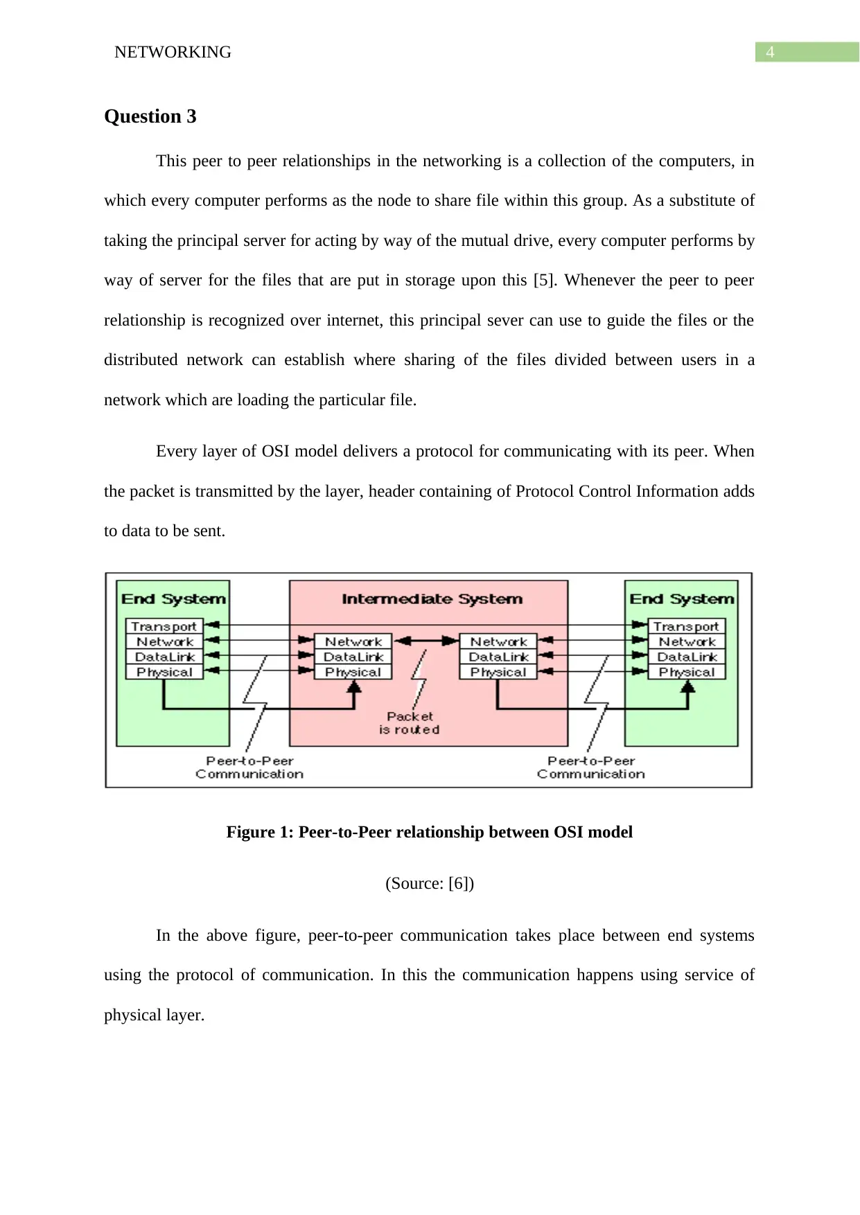
Every layer of OSI model delivers a protocol for communicating with its peer. When
the packet is transmitted by the layer, header containing of Protocol Control Information adds
to data to be sent.
Figure 1: Peer-to-Peer relationship between OSI model
(Source: [6])
In the above figure, peer-to-peer communication takes place between end systems
using the protocol of communication. In this the communication happens using service of
physical layer.
Question 3
This peer to peer relationships in the networking is a collection of the computers, in
which every computer performs as the node to share file within this group. As a substitute of
taking the principal server for acting by way of the mutual drive, every computer performs by
way of server for the files that are put in storage upon this [5]. Whenever the peer to peer
relationship is recognized over internet, this principal sever can use to guide the files or the
distributed network can establish where sharing of the files divided between users in a
network which are loading the particular file.
Every layer of OSI model delivers a protocol for communicating with its peer. When
the packet is transmitted by the layer, header containing of Protocol Control Information adds
to data to be sent.
Figure 1: Peer-to-Peer relationship between OSI model
(Source: [6])
In the above figure, peer-to-peer communication takes place between end systems
using the protocol of communication. In this the communication happens using service of
physical layer.
5NETWORKING
Question 4
For reducing the noise due to the electromagnetic interference caused in the bus in the
automotive industry, the SPI is the perfect standard protocol. SPI is the single ended signal
transmission protocol that is more susceptible to the noise. Sending the SPI signal over the
LVDS driver also receiver helps with reduction of the noise.
Question 5
The four communal sources of the impairment on the communications links that are
copper based, are open wire, twisted pair, coaxial cable and optical fiber.
i) Open wire: It is utilized traditionally for describing electrical wire threaded along the
power poles. In this only one single wire is strung between the poles [8]. In this, no protection
or shielding from the noise interference is used. It is used for the data transmission within a
small distances under 20 ft.
ii) Twisted pair cable: It is less costly also most extensively used. In this wires, twisted pair
cabling are warped composed in the couples. Every couples would contains one +ve data
signal passing wire and one –ve data signal passing wire. If any noise appears in any of this
two wire, this noise is also occur in the other wire of this pair because this wires are opposite
polarities. Whenever noise occurs on the both of the wires, this nulls or cancels itself out at
acceptance end. This cables are mostly used in the systems which used the transmission or
balanced line method.
iii) Coaxial cable:
This cable is mostly substituted by the cabling of twisted pair for installation of LAN
that is Local Area Network contained by the constructions. It carries the signals of the ranges
⊘ This is a preview!⊘
Do you want full access?
Subscribe today to unlock all pages.
Trusted by 1+ million students worldwide
6NETWORKING
of advanced frequency than the twisted pair cable. This has an essential code conductor of the
solid or the standard wire that is surrounded in the insulating cover.
iv) Optical fiber:
It is the media of glass cabling which sends the network signals using the light. It has
the capacity of higher bandwidth than the copper cabling. This is the plastic fiber or glass
which transports light alongside with the extent of this. It is widely used in the
communication however they allow broadcast over the extended distances also at the
advanced bandwidth or data rate than the additional forms of the communication.
Question 6
Noise mitigation method is tried to suppress power of the noise, exclude non-linearly
or clip noise contaminated data rather than of reconstructing noises also cancelling them out.
In this, current in the noise foundation generates the arena which reasons the consistent
current in conductor [9]. The CSDM method that is Compressive Sensing Based Narrow
Band Interference and Impulsive Noise Mitigation is appropriate method for this situation.
The general way to reduce the noise is to differentiate or separate sources of the noise from
uses of the noise sensitive.
Question 7
In the network of fast packet if some of the samples of signal are vanished also their
situation are known, then this is probable to improve the impeccable plan, a theorem can use
[10]. The name of this theorem is Nyquist-Shannon sampling theorem. This theorem stated,
the least sampling frequency of the signal so as to this will not misrepresent its fundamental
material and should be twice frequency of the maximum frequency constituent.
Paraphrase This Document
Need a fresh take? Get an instant paraphrase of this document with our AI Paraphraser
7NETWORKING
Question 8
The difference between the single mode fiber also the multi-mode fiber are as
follows:
i) In the single mode fiber, single mode is spread via fiber, on other hand, in multi-mode fiber
several mode are spread via fiber [11].
ii) Single mode fiber includes the small core, on the other hand, multi-mode fiber includes the
large core.
iii) Single mode fiber uses for long distance communication, on other hand the multi-mode
fiber uses for the short distance communication.
iv) Single mode fiber has the less reduction, in contrast multi-mode fiber has the more
reduction.
v) Single mode has the lower bandwidth whereas multi-mode has the higher bandwidth.
vi) Single-mode permits the less distribution, on the other hand, multi-mode permits more
distribution.
vii) Single-mode is less difficult and costly, on the other hand, multi-mode is more difficult
and costly.
Question 9
Numerous devices are networked to the controller or PC, the systems applied for the
Human Machine Interface (HMI) or any other processes. For this scenario, a serial
communication standard is selected for this presentation to accomplish an improved
presentation [12]. Offering the serial communication bus options, the HMI achieve the
communication link of robust data in the environments of manufacturing and harsh industry.
8NETWORKING
The RS-232 diagnostic port delivers isolation between serial cable networks also linked
systems for defending against voltage spikes also the ground loops within noisy atmosphere
and progress the dependability of the system.
Question 10
RS-232 transmitters also the receivers can design to the communal standard, this is
very much important for defining the levels of voltage which establish two logical states that
essential for the transmission of data[13]. For logical state 1, the RS-232 signal line voltage
levels is -3 to -25 volts and for the logical state 0, the RS-232 signal line voltage levels is +3
to +25 volts. It is necessary for defining voltage states on behalf of the control signals as
these are hugely applied inside the RS-232.
Question 11
The differential voltage is the floating means that this has no reference to ground.
This measurement takes as difference of the voltage between the two wires. The key benefit
of this is to reject the noise.
The standard RS-485 identifies a few differential voltage (Pin A-Pin B)> +200mV as
the logic one also a few differential voltage underneath the -200mV as the logic 0 [14]. The
big delta between driver’s + and – 1.5V differential output voltage also receiver’s + and –
200mV threshold produces the worthy noise immunity also capability for handling reduction
from the extended cables.
Question 12
The determination of the bias resistors in the RS-485 systems is that bias resistors
present the shared mode load as well to corresponding transceiver input resistance. Also
lower value of the bias resistor is helpful to turn negative for the resulting numbers in the
⊘ This is a preview!⊘
Do you want full access?
Subscribe today to unlock all pages.
Trusted by 1+ million students worldwide
9NETWORKING
transceiver unit loads [15]. Also the high margins of noise needed in the industrial networks
claim the low values of the bias resistors in which the common mode load can be
overburdened drive capability of the standard Rs-485 transceivers.
Question 13
Comparison and contrasting of the RS-232 and RS-485 are as follows:
i) The RS-232 is the component of the physical layer of OSI model. But the bulk of work
handle by the Application layer. It delivers the hardware means of the sending also receiving
the data on the transporter containing describing cables, physical aspects also cards.
On other hand, the RS-485 only addresses the layer one that is the physical layer and
can add also the layer two that is the data link layer in OSI model.
ii) RS-232 uses the simple parallel wires or the twisted pair as their communication medium.
On other hand, RS-485 uses the standard transmission medium that is the twisted pair
cable of one or the other #22 or #24 AWG solid wire. For full duplex operation, four wire
cables are used.
iii) Shielding that is the common method for preventing the noise in RS232 lines which
attempts to preserve the fields of hostile magnetic away from all the signal lines.
On other hand, the twisted pairs in the RS485 communication though adds resistance
that is much improved method to contest for the noise. Magnetic fields are permitted to
permit but do no damage. For high noise protection, mixture of twisting and the shielding is
used such as cables of foiled twisted pair networking, STP also shielded twisted pair and
FTP.
iv) Rs-232 standard expresses the communication technique in which the data is referred on
the physical channel bit by bit. All the information must break in data words.
Paraphrase This Document
Need a fresh take? Get an instant paraphrase of this document with our AI Paraphraser
10NETWORKING
On other hand, RS-485 standard permits numerous devices up to 32 for
communicating at the half duplex on the single pair of wires with the ground wire at distances
up to the 1200 meters.
Question 14
There are many serial communication standard are present in which the RS485 is
interconnects over a bus. This RS 485 can controlled the connected devices up to 32. By this ,
users can permits in the facilities of manufacturing for connecting the larger applications also
the total machines with a single protocol.
Question 15
The serial port is the interface via which the peripherals can connect as the
communication channel using the serial protocol [16]. The most common type of the serial
protocol in the modern computers is RS232 that is used for connecting the computer also the
peripheral devices for allowing the serial data exchange between them.
11NETWORKING
References
[1] J.M. Jaworski, J. Bek, and A.J. Fiok, Impact of modern instrumentation on the system of
basic concepts in metrology, ACTA IMEKO, 3(1), pp.41-46, 2014.
[2] F. Barrero, J.A. Guevara, E. Vargas, S. Toral, and M. Vargas, Networked transducers in
intelligent transportation systems based on the IEEE 1451 standard, Computer Standards &
Interfaces, 36(2), pp.300-311, 2014.
[3] S.S. Shadrin, A.M. Ivanov, and K.E. Karpukhin, Using data from multiplex networks on
vehicles in road tests, in intelligent transportation systems, and in self-driving cars, Russian
engineering research, 36(10), pp.811-814, 2016.
[4] N.R. Akbashev, and A.V. Solodovnikov., Analysis of a management system for industrial
safety at oil refineries, Chemical and Petroleum Engineering, 50(7-8), pp.542-546, 2014.
[5] D.O. Guaraglia, and J.L. Pousa, Introduction to modern instrumentation: for hydraulics
and environmental sciences, Walter de Gruyter GmbH & Co KG, 2014.
[6] G. Bora, S. Bora, S. Singh, and S.M. Arsalan, OSI reference model: An overview,
International Journal of Computer Trends and Technology (IJCTT), 7(4), pp.214-218, 2014.
[7] S.A. Abdulazeez, A. El Rhalibi, M. Merabti, and D. Al-Jumeily, Survey of solutions for
Peer-to-Peer MMOGs, In 2015 International Conference on Computing, Networking and
Communications (ICNC) (pp. 1106-1110), IEEE, 2015, February.
[8] X.C. Tong, Advanced materials and design for electromagnetic interference shielding,
CRC press, 2016.
[9] M.N. Sadiku, S.M. Musa, and S.R. Nelatury, Free space optical communications: an
overview, European scientific journal, 12(9), 2016.
⊘ This is a preview!⊘
Do you want full access?
Subscribe today to unlock all pages.
Trusted by 1+ million students worldwide
1 out of 14
Related Documents


Your All-in-One AI-Powered Toolkit for Academic Success.
+13062052269
info@desklib.com
Available 24*7 on WhatsApp / Email
![[object Object]](/_next/static/media/star-bottom.7253800d.svg)
Unlock your academic potential
Copyright © 2020–2026 A2Z Services. All Rights Reserved. Developed and managed by ZUCOL.