ME 413: Gear Design Project for Industrial Motion Controller

Verified

Added on  2022/08/12

|11
|704
|73
Project
AI Summary
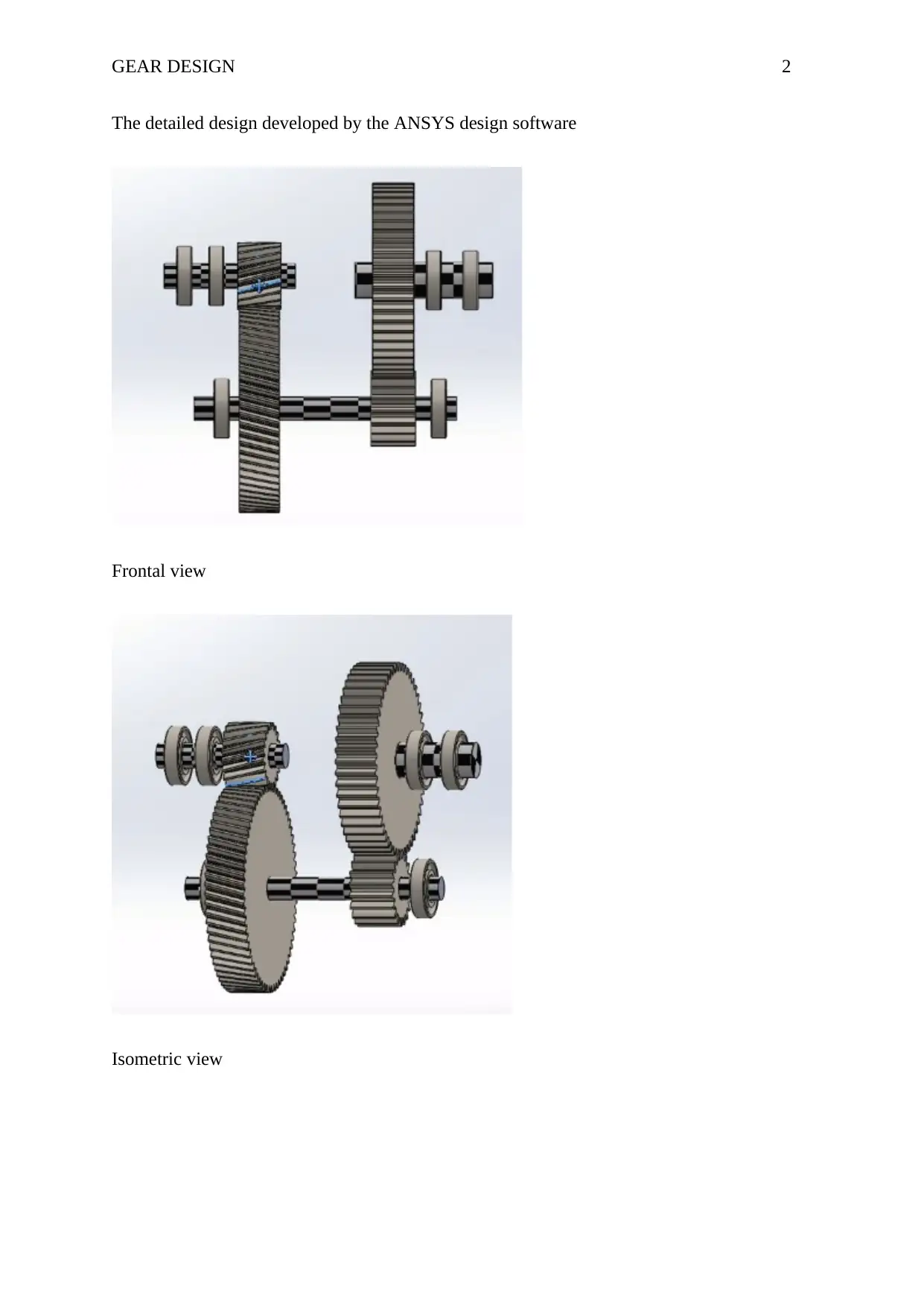
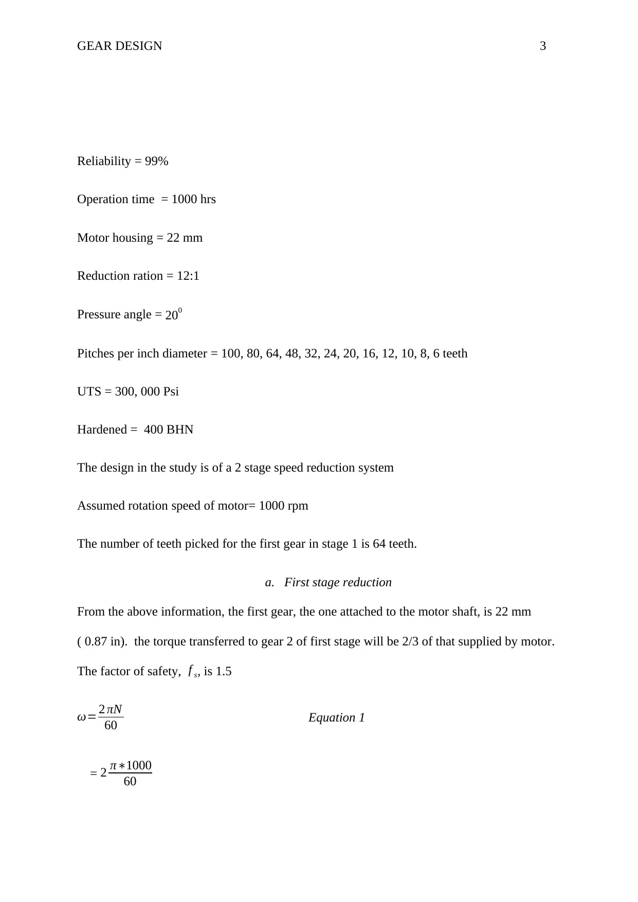
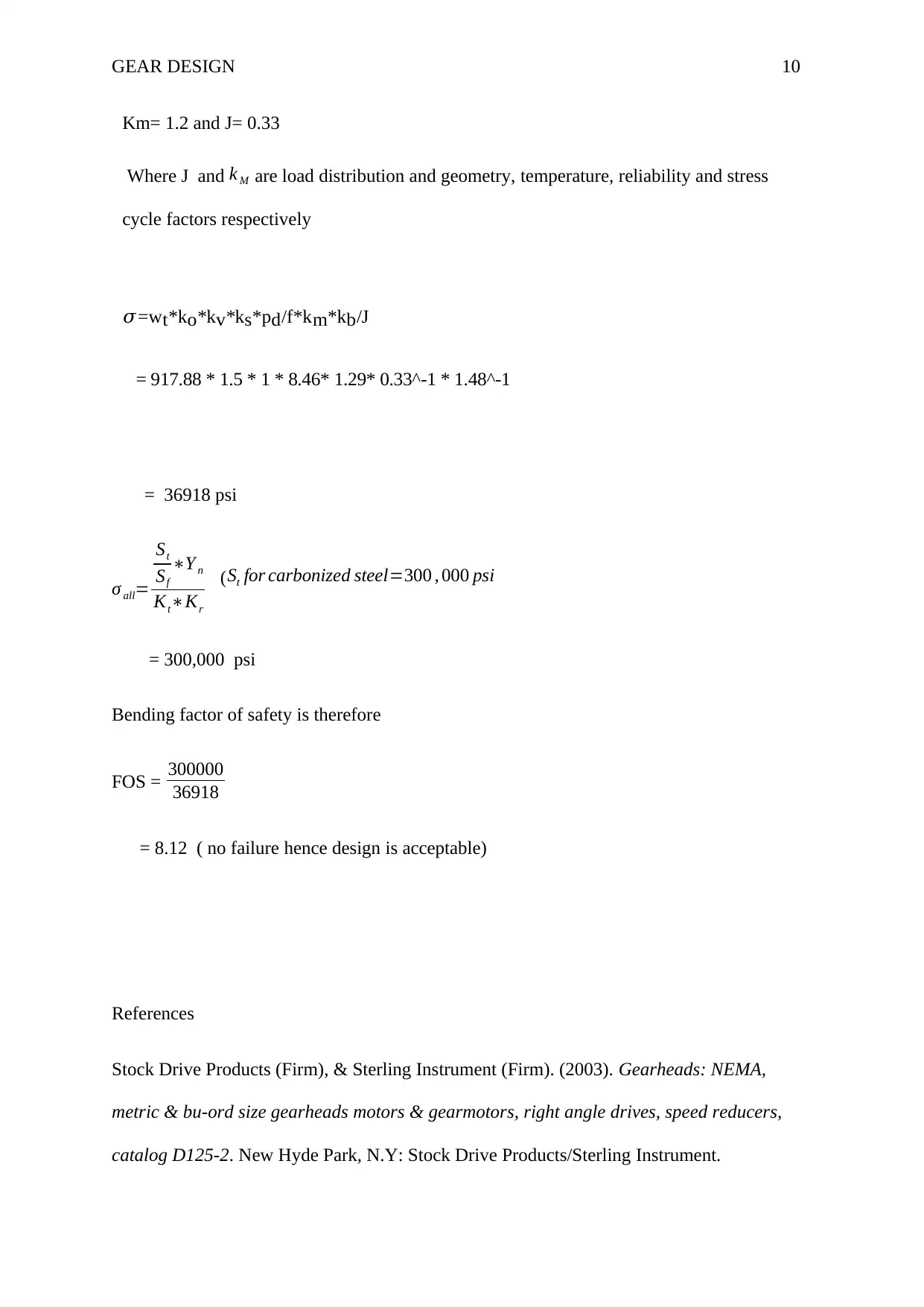
This assignment presents a detailed design of a two-stage speed reduction system for an industrial motion controller, adhering to specifications such as a 12:1 reduction ratio, 99% reliability, and a motor housing diameter of 22 mm. The design process utilizes ANSYS design software and includes calculations for torque, angular velocity, and module selection based on wear strength. The solution considers factors such as the number of teeth, pressure angle, and material properties (UTS and BHN) to determine gear dimensions and ensure design integrity. The analysis involves calculating bending stress and the factor of safety for both stages of reduction, ensuring the gear design meets the required performance and reliability criteria. The project concludes with a comprehensive evaluation of the design's ability to withstand operational stresses and avoid failure.
Document Page
Running Head: GEAR DESIGN
GEAR DESIGN
Name
Institute of Affiliation
Date
tabler-icon-diamond-filled.svg

Paraphrase This Document

Need a fresh take? Get an instant paraphrase of this document with our AI Paraphraser
Document Page
GEAR DESIGN 2
The detailed design developed by the ANSYS design software
Frontal view
Isometric view
Document Page
GEAR DESIGN 3
Reliability = 99%
Operation time = 1000 hrs
Motor housing = 22 mm
Reduction ration = 12:1
Pressure angle = 200
Pitches per inch diameter = 100, 80, 64, 48, 32, 24, 20, 16, 12, 10, 8, 6 teeth
UTS = 300, 000 Psi
Hardened = 400 BHN
The design in the study is of a 2 stage speed reduction system
Assumed rotation speed of motor= 1000 rpm
The number of teeth picked for the first gear in stage 1 is 64 teeth.
a. First stage reduction
From the above information, the first gear, the one attached to the motor shaft, is 22 mm
( 0.87 in). the torque transferred to gear 2 of first stage will be 2/3 of that supplied by motor.
The factor of safety, f s, is 1.5
ω= 2 πN
60 Equation 1
= 2 π1000
60
Document Page
GEAR DESIGN 4
= 105 rad/sec
Also, the gear head will be coupled with CVT.
Power = torque * angular velocity Equation 2
Torque = power
angular velocity
= 6 w
105rad /sec
= 0.0572 N/m
The speed of gear 2 of stage one
p=ω1T 1=ω2T 2 Equation 3
6 = 2
3¿(0.0572) * ω2
ω2=157.3
158 rad/sec
The number of teeth in gear 2 of stage 1 is as follows
ω1
ω2
= T2
T1
105
158 = T 2
64
T 2=96
tabler-icon-diamond-filled.svg

Paraphrase This Document

Need a fresh take? Get an instant paraphrase of this document with our AI Paraphraser
Document Page
GEAR DESIGN 5
b. Now estimating the module on basis of wear strength
m=
[ 60106
3.14 { ( kw ) CsFs
z2npCv( b
m )QK }] 1
3
Equation 4
Where CS=1.5 , f s=1.5 ,
Cv= 3
3+v = 3
8 (v is assumed 5 m
s ), Equation 5
Q= 2 Z g
ZgZ p
= 296
9664 =6 Equation 6
K¿ ( 0.156 { BNH }
100 ) = ( 0.156400
100 )=0.624 Now replacing this values in equation 4 above
M=
[ 60106
3.14 { ( 6 )1.51.5
z2963
8 ( b
m )60.624 }] 1
3
= 3.53
The module selected will be 3mm
c. Checking the design
Pt =2M t
d p
= 235000
54
= 1296.4
V= 3.14d pn p
60 103
Document Page
GEAR DESIGN 6
= 5.79 m/s
cv= 3
3+5.79 ( refer equation 5)
Peff = Cs
Cv
Pt
= 1.5648.2
0.3412
= 5697.67
f s= Sb
Peff
Where sb =mbσ bY
= 3 * 30 * 400* 0.308
= 11088 N
So
Fs= 11088
5697.67
= 1.94 (it greater than the 1.5 factor of safety that was the design requirement)
Therefore, the 3mm module is justified.
d. The minimum number of teeth required to avoid interference
N p= 2 k
( 1+2 m ) sin2 θ ( m+ m2 + ( 1+2 m ) sin2 θ )
= 2
( 1+ 23 ) sin2 20 ( 3+ 32+ ( 1+ 23 ) sin2 20 )
= 14.9 teeth
Document Page
GEAR DESIGN 7
15 teeth
Where θ = 20, k=1 and m=3
Second stage reduction
The since the overall speed reduction of the system has to be 12:1, the initial reduction
achieved 3: 2 speed reduction. This has to be further reduced by a ration 4: 1.
From the speed and number of teeth relationship, the new number of teeth can be obtained as
follows;
ω3
ω4
=T 3
T 4
For easy of design, the size of gear number 2 was equal to the size of gear number 3 in terms
of teeth number and diameter. Therefore,
t3=96 and ω3=¿ 158 rad/sec
Since the expected ration is 4:1 then
4= T 4
T 3
= T 4
96
384= T 4
Failure criteria
For failure to take place, the tooth stress must exceed the yield strength.
Diameteral pitch= 1
m
tabler-icon-diamond-filled.svg

Paraphrase This Document

Need a fresh take? Get an instant paraphrase of this document with our AI Paraphraser
Document Page
GEAR DESIGN 8
¿ 25. 4
3
¿ 8. 46 teeth
inch
V = 3.14dpnp
12
V =1136.1 ft / min.
W= 33000h
V
= 3300010
1136.1
= 290.46 lbf
a. Failure through bending
i. First stage
Velocity factor
Kv=1200+ V
1200
¿ 1.94 .
Overload factor Ko=1.5
Ks=1 = Kb = k t=kr=Y n
where k b , K s , kt , krY n are Size factor and rim thickness factor respectively
Km= 1.2 and J= 0.33
Where J and k M are load distribution and geometry, temperature, reliability and stress
cycle factors respectively
Document Page
GEAR DESIGN 9
𝜎=w t *k o *k v *k s *p d /f*k m *k b /J
= 22036.1129 psi
σ all=
St
Sf
Y n
KtKr
(St for carbonized steel=300 , 000 psi
= 300,000 psi
Bendign factor of safety is therefore
FOS = 300000
22036.1129
= 13.61 ( no failure hence design is acceptable)
ii. Second stage
Velocity factor
Kv=1200+ V
1200
¿ 1.94 .
Overload factor Ko=1.5
Ks=1 = Kb = k t=kr=Y n
where k b , K s , kt , krY n are Size factor and rim thickness factor respectively
Document Page
GEAR DESIGN 10
Km= 1.2 and J= 0.33
Where J and k M are load distribution and geometry, temperature, reliability and stress
cycle factors respectively
𝜎=w t *k o *k v *k s *p d /f*k m *k b /J
= 917.88 * 1.5 * 1 * 8.46* 1.29* 0.33^-1 * 1.48^-1
= 36918 psi
σ all=
St
Sf
Y n
KtKr
(St for carbonized steel=300 , 000 psi
= 300,000 psi
Bending factor of safety is therefore
FOS = 300000
36918
= 8.12 ( no failure hence design is acceptable)
References
Stock Drive Products (Firm), & Sterling Instrument (Firm). (2003). Gearheads: NEMA,
metric & bu-ord size gearheads motors & gearmotors, right angle drives, speed reducers,
catalog D125-2. New Hyde Park, N.Y: Stock Drive Products/Sterling Instrument.
tabler-icon-diamond-filled.svg

Paraphrase This Document

Need a fresh take? Get an instant paraphrase of this document with our AI Paraphraser
Document Page
GEAR DESIGN 11
chevron_up_icon
1 out of 11
circle_padding
hide_on_mobile
zoom_out_icon
[object Object]