Information System Development for a Game Cafe Analysis
VerifiedAdded on 2022/11/29
|14
|1406
|378
Presentation
AI Summary
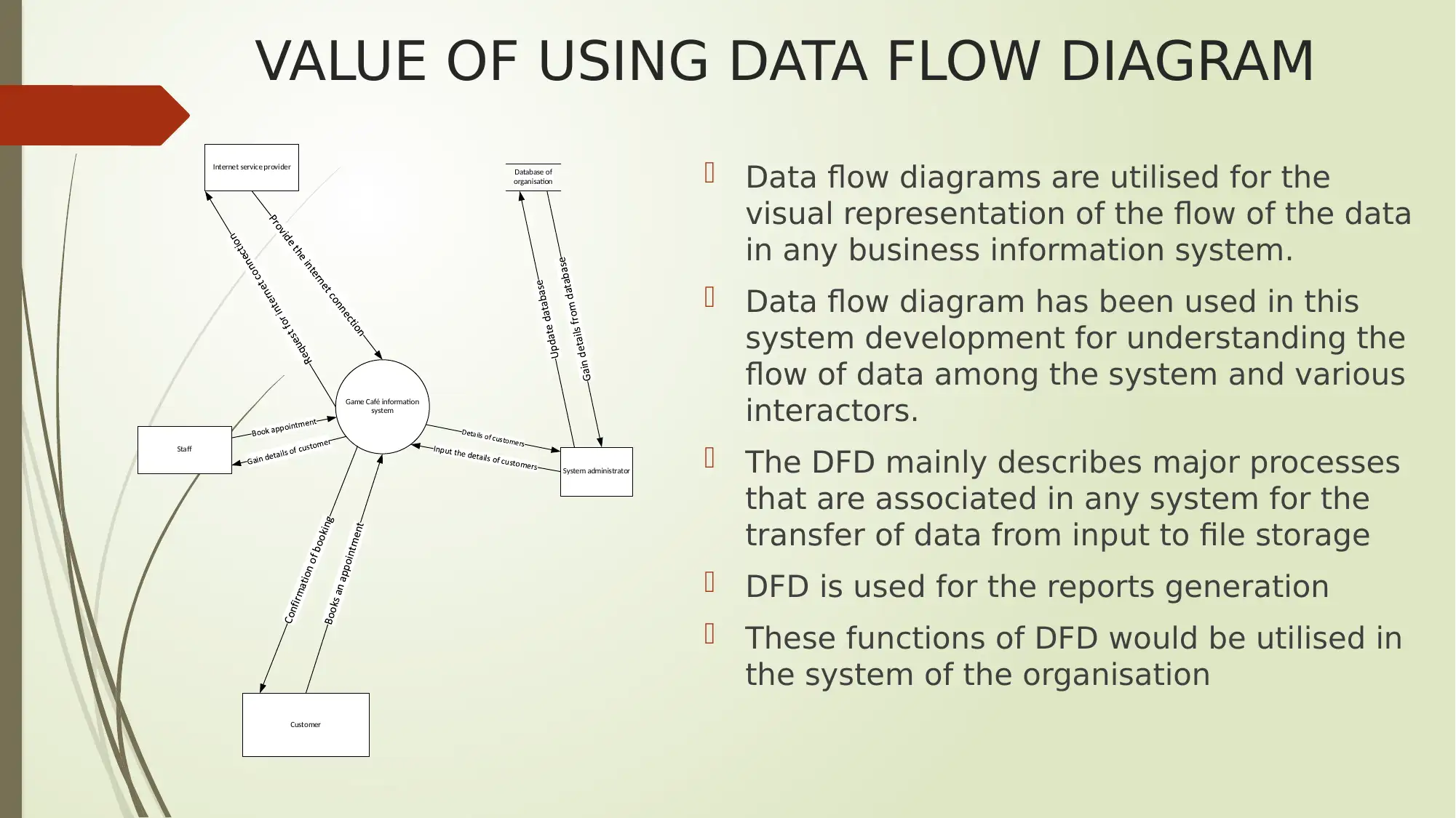
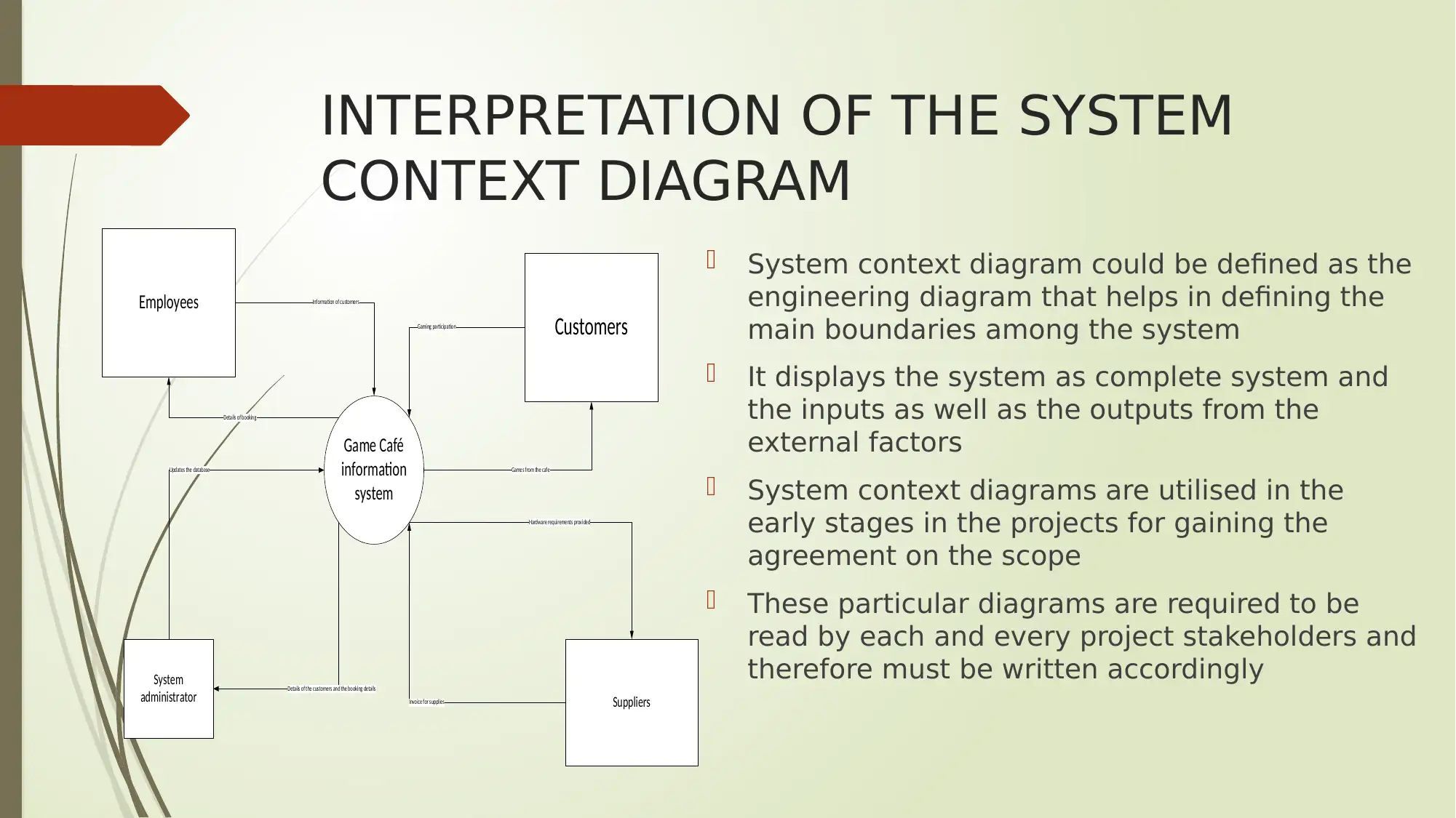
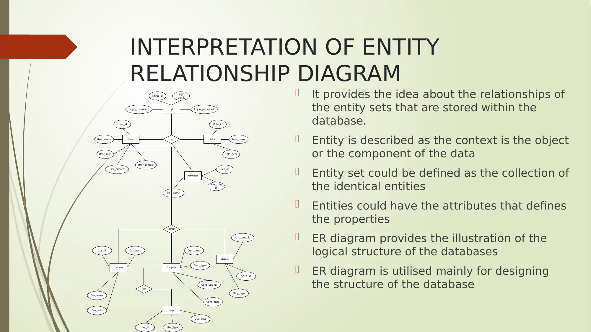
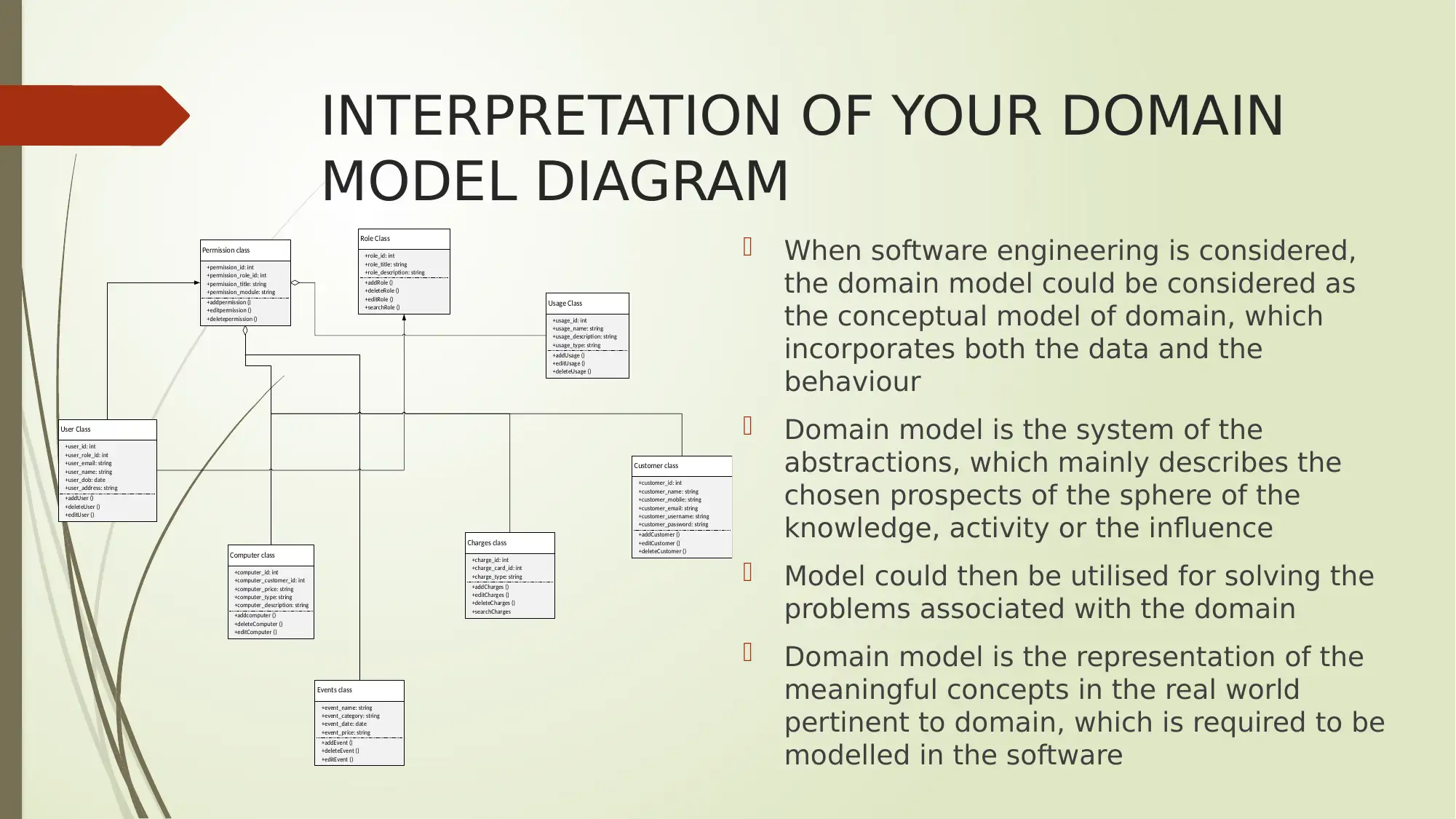
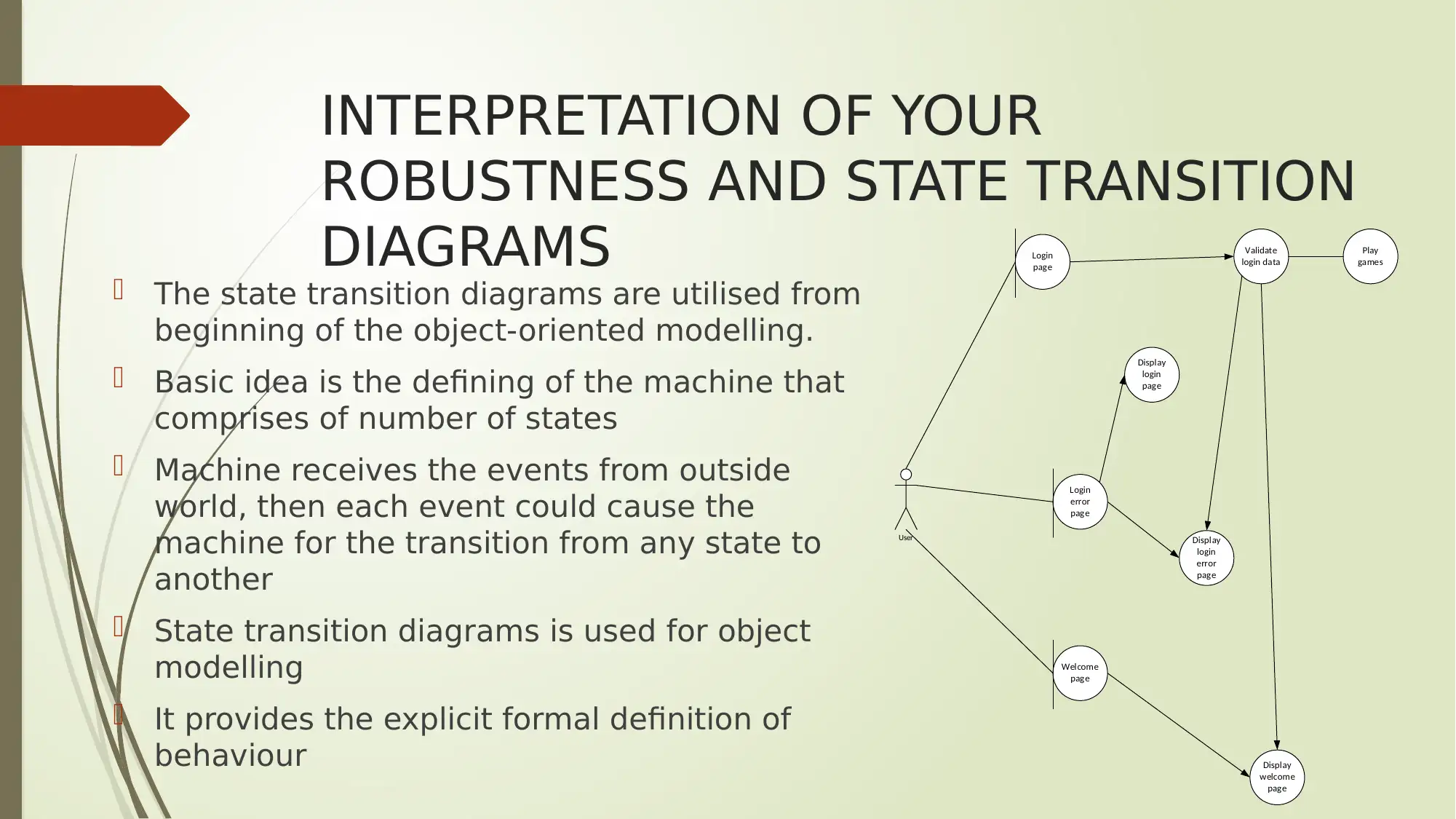
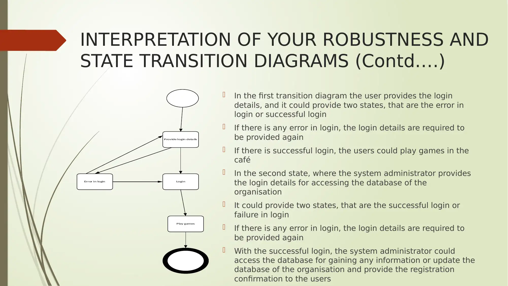
This presentation provides a detailed analysis of the information system development for a game cafe. It begins with an explanation of Data Flow Diagrams (DFDs) and their role in visualizing data flow within the system, including logical and physical DFDs. The presentation then interprets the system context diagram, identifying interactions between employees, system administrators, suppliers, and customers. Following this, the Entity Relationship (ER) diagram is examined to illustrate relationships within the database, including users, roles, charges, and game usage. The domain model diagram is interpreted, showing user permissions and class aggregations. Furthermore, the presentation analyzes robustness and state transition diagrams, demonstrating login processes and database access. Finally, the presentation reflects on object-oriented techniques and concludes with a bibliography of relevant sources.
Contribute Materials
Your contribution can guide someone’s learning journey. Share your
documents today.

INFORMATION SYSTEM
DEVELOPMENT FOR
GAME CAFE
DEVELOPMENT FOR
GAME CAFE
Secure Best Marks with AI Grader
Need help grading? Try our AI Grader for instant feedback on your assignments.

VALUE OF USING DATA FLOW DIAGRAM
Data flow diagrams are utilised for the
visual representation of the flow of the data
in any business information system.
Data flow diagram has been used in this
system development for understanding the
flow of data among the system and various
interactors.
The DFD mainly describes major processes
that are associated in any system for the
transfer of data from input to file storage
DFD is used for the reports generation
These functions of DFD would be utilised in
the system of the organisation
Game Café information
system
Internet service provider Database of
organisation
System administrator
Staff
Customer

VALUE OF USING DATA FLOW
DIAGRAM (Contd…..)
The DFD could be easily divided into the physical section and the logical
section
The logical DFD mainly describes the flow of the data within any system
for performing any specific functionality of any business
The implementation of logical data flow is described using the physical
data flow diagram
DFD helps in the graphic representation of the processes, functions that
could capture, store, manipulate or distribute the data among the
system and the environment

INTERPRETATION OF THE SYSTEM
CONTEXT DIAGRAM
System context diagram could be defined as the
engineering diagram that helps in defining the
main boundaries among the system
It displays the system as complete system and
the inputs as well as the outputs from the
external factors
System context diagrams are utilised in the
early stages in the projects for gaining the
agreement on the scope
These particular diagrams are required to be
read by each and every project stakeholders and
therefore must be written accordingly
Game Café
information
system
Employees
Suppliers
System
administrator
Customers
Information of customers
Updates the database
Hardware requirements provided
Details of booking
Games from the cafe
Invoice for supplies
Details of the customers and the booking details
Gaming participation
Secure Best Marks with AI Grader
Need help grading? Try our AI Grader for instant feedback on your assignments.

INTERPRETATION OF THE SYSTEM
CONTEXT DIAGRAM (Contd…..)
In the system context diagram of the Game café, it could be interpreted
that the employees could use this system for providing the information of
the customers in the system and gain the details of any appointment from
the system
The system administrator could use the system for updating the database
of the organisation along with providing the authorisation to the
employees and gain information about booking details from the system
The suppliers of the company could provide the invoice of the supplies that
are provided to the organisation and get the notification of any
requirements of the organisation that are required to be provided
The customers could use this system for providing the participation details
in the system of the organisation and games could be gained from the
organisation.

INTERPRETATION OF ENTITY
RELATIONSHIP DIAGRAM
It provides the idea about the relationships of
the entity sets that are stored within the
database.
Entity is described as the context is the object
or the component of the data
Entity set could be defined as the collection of
the identical entities
Entities could have the attributes that defines
the properties
ER diagram provides the illustration of the
logical structure of the databases
ER diagram is utilised mainly for designing
the structure of the database
Has
Manage
Login
User Roles
Permission
Computer
Charges
Customer
Usage
Login_username
Login_id Login
role_id
Login_password
Role_id
Role_name
Role_desc
Per_id
Per_role
id
Per_name
User_id
User_name
User_mail
User_address
User_mobile
Has
Cus_passCus_id
Cus_add
Cus_name
Com_desc
Com_type
Com_Cus_id
Com_price
Crg_cand_id
Chrg_id
Chrg_type
Usa_typeUsa_id
Usa_desc

INTERPRETATION OF ENTITY
RELATIONSHIP DIAGRAM (Contd…..)
From the ER diagram of the Game Café, it could be observed that the
organisation has the login function, the users, roles, permission
The organisation manages the charges of the café, customer, computer,
and the usage of internet as well as the games in the organisation
The system of the organisation helps in functioning the system of the
organisation as per the requirements of the customers
It allows the users to play any games they wish and then pay the
charges for the games that are played.
Some of the common weakness in this stage are the inability of the
customers to access the computers of the organisation that are not
properly configured for playing the games with ease.
Paraphrase This Document
Need a fresh take? Get an instant paraphrase of this document with our AI Paraphraser

INTERPRETATION OF YOUR DOMAIN
MODEL DIAGRAM
When software engineering is considered,
the domain model could be considered as
the conceptual model of domain, which
incorporates both the data and the
behaviour
Domain model is the system of the
abstractions, which mainly describes the
chosen prospects of the sphere of the
knowledge, activity or the influence
Model could then be utilised for solving the
problems associated with the domain
Domain model is the representation of the
meaningful concepts in the real world
pertinent to domain, which is required to be
modelled in the software
Role Class
+role_id: int
+addRole ()
+deleteRole ()
Permission class
+permission_module: string
+addpermission () Usage Class
+usage_description: string
+deleteUsage ()
User Class
+user_address: string
+addUser ()
Customer class
+customer_username: string
+addCustomer ()
Computer class
+computer_description: string
+addcomputer ()
Charges class
+charge_card_id: int
+editCharges ()
Events class
+event_price: string
+addEvent ()
+role_title: string
+role_description: string
+editRole ()
+searchRole ()+editpermission ()
+deletepermission ()
+permission_id: int
+permission_title: string
+permission_role_id: int
+addUsage ()
+usage_id: int
+usage_type: string
+usage_name: string
+editUsage ()
+deleteCustomer ()
+editCustomer ()
+customer_name: string
+customer_id: int
+customer_mobile: string
+customer_password: string
+customer_email: string
+charge_id: int
+charge_type: string
+searchCharges
+addCharges ()
+deleteC harges ()
+deleteUser ()
+editUser ()
+user_dob: date
+user_name: string
+user_id: int
+user_role_id: int
+user_email: string
+computer_id: int
+computer_customer_id: int
+computer_type: string
+computer_price: string
+deleteComputer ()
+editComputer ()
+event_name: string
+event_category: string
+event_date: date
+deleteEvent ()
+editEvent ()

INTERPRETATION OF YOUR DOMAIN
MODEL DIAGRAM (Contd…..)
It could be interpreted from the domain model diagram that the user of
the system have to take permission prior accessing the system of the
organisation.
There is an aggregation of the computer class, events class, charge
class, and the customer class with the permission class as all these
classes are included in the permission class
The user class is in direct association with the role class and the
permission class
The usage class is aggregated with the permission class that forms the
direct association for the system.

INTERPRETATION OF YOUR
ROBUSTNESS AND STATE TRANSITION
DIAGRAMS
The state transition diagrams are utilised from
beginning of the object-oriented modelling.
Basic idea is the defining of the machine that
comprises of number of states
Machine receives the events from outside
world, then each event could cause the
machine for the transition from any state to
another
State transition diagrams is used for object
modelling
It provides the explicit formal definition of
behaviour
Login
page
Login
error
page
Welcome
page
User
Validate
login data
Play
games
Display
login
page
Display
login
error
page
Display
welcome
page
Secure Best Marks with AI Grader
Need help grading? Try our AI Grader for instant feedback on your assignments.

INTERPRETATION OF YOUR ROBUSTNESS AND
STATE TRANSITION DIAGRAMS (Contd….)
In the first transition diagram the user provides the login
details, and it could provide two states, that are the error in
login or successful login
If there is any error in login, the login details are required to
be provided again
If there is successful login, the users could play games in the
café
In the second state, where the system administrator provides
the login details for accessing the database of the
organisation
It could provide two states, that are the successful login or
failure in login
If there is any error in login, the login details are required to
be provided again
With the successful login, the system administrator could
access the database for gaining any information or update the
database of the organisation and provide the registration
confirmation to the users
Provide login details
Error in login Login
Play games

REFLECTION ON THE OBJECT ORIENTED
TECHNIQUES
The object oriented analysis could be described as the process of
identifying the software engineering requirements and the development
of the software specifications in the terms of the object model of the
software system that includes the interacting objects.
The object oriented design includes the implementation of conceptual
model that is produced through the object oriented analysis.
Within OOD, the concepts within the analysis model that are
significantly technology independent, are suitably mapped onto
implementing the classes, the identification of the constraints is done
and the designing of the interfaces is done that leads to the model for
any solution domain, which is the detailed description of the methods by
which the system has to be created on the concrete technologies.

BIBLIOGRAPHY
Casella, F., Bartolini, A., Pasquini, S. and Bonuglia, L., 2016, October. Object-oriented
modelling and simulation of large-scale electrical power systems using modelica: A first
feasibility study. In IECON 2016-42nd Annual Conference of the IEEE Industrial
Electronics Society (pp. 6298-6304). IEEE.
Couckuyt, I., Dhaene, T. and Demeester, P., 2014. ooDACE toolbox: a flexible object-
oriented Kriging implementation. The Journal of Machine Learning Research, 15(1),
pp.3183-3186.
Damic, V. and Montgomery, J., 2016. Mechatronics by bond graphs: an object-oriented
approach to modelling and simulation. Springer.
Ferretti, G., Leva, A. and Scaglioni, B., 2014. Object-oriented modelling of general
flexible multibody systems. Mathematical and Computer Modelling of Dynamical
Systems, 20(1), pp.1-22.
Jeong, W., Kim, J.B., Clayton, M.J., Haberl, J.S. and Yan, W., 2016. A framework to
integrate object-oriented physical modelling with building information modelling for
building thermal simulation. Journal of Building Performance Simulation, 9(1), pp.50-69.
Paraphrase This Document
Need a fresh take? Get an instant paraphrase of this document with our AI Paraphraser

1 out of 14
Related Documents

Your All-in-One AI-Powered Toolkit for Academic Success.
+13062052269
info@desklib.com
Available 24*7 on WhatsApp / Email
Unlock your academic potential
© 2024 | Zucol Services PVT LTD | All rights reserved.