COIT20248: Information Systems Design and Development Report
VerifiedAdded on 2023/06/04
|13
|1512
|265
Report
AI Summary
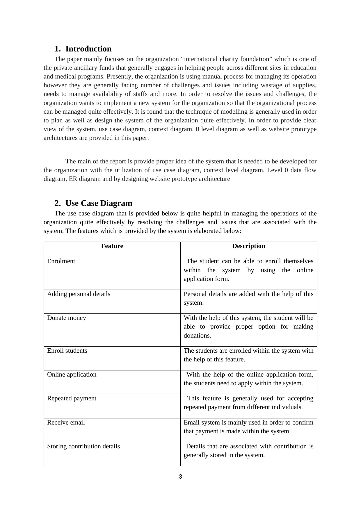
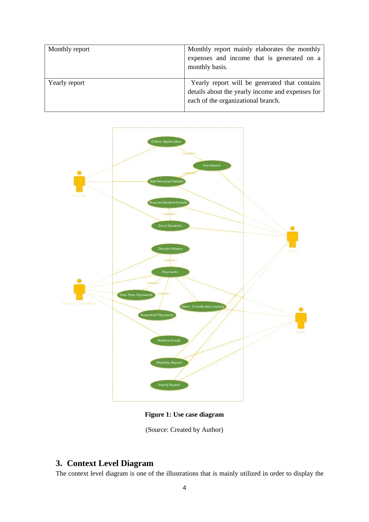
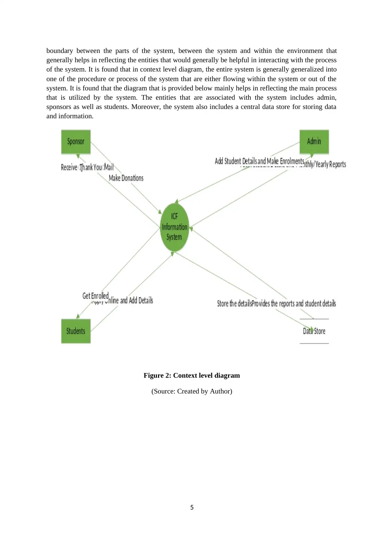
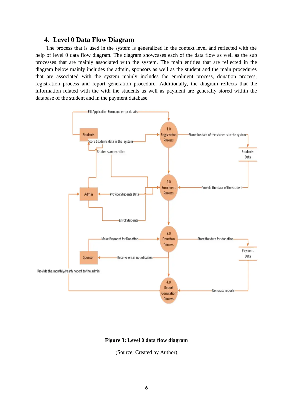
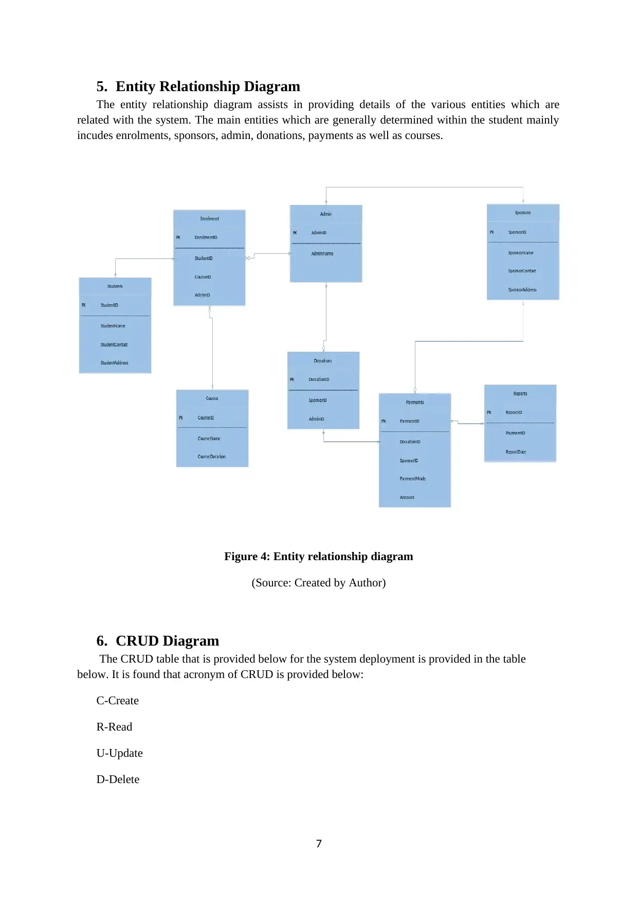
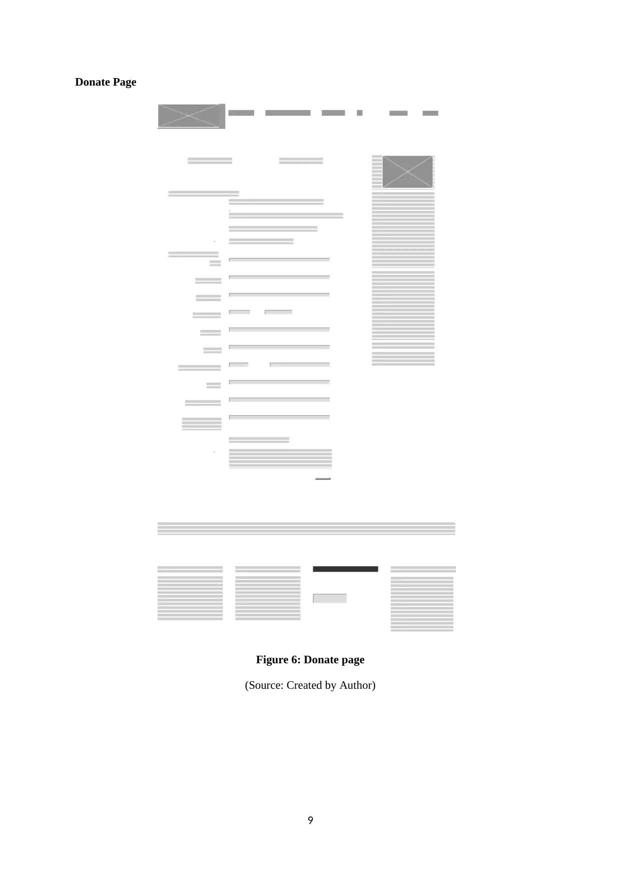
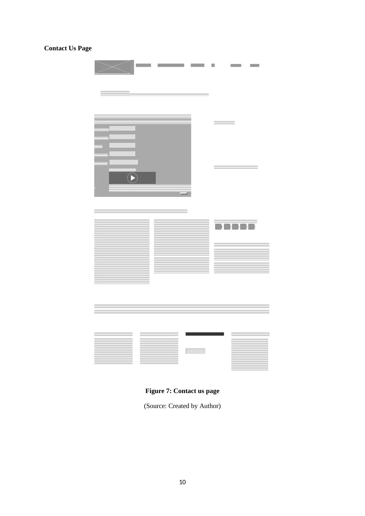
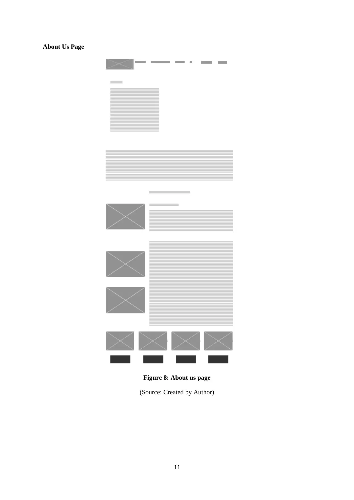
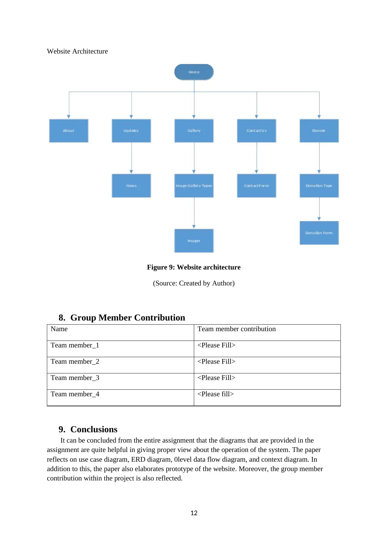
This report details the systems design and development for the International Charity Foundation, addressing challenges in its manual operational processes. The assignment, part of the COIT20248 course, encompasses a range of modeling techniques to design an efficient system. It includes a Use Case Diagram outlining features such as enrollment, donations, and report generation; a Context Level Diagram illustrating system boundaries and entities; a Level 0 Data Flow Diagram depicting processes like enrollment and donation; an Entity Relationship Diagram showcasing entity relationships; and a CRUD Diagram for system deployment. Additionally, a website prototype is designed to enhance user experience. The report concludes with a discussion of group member contributions and overall conclusions, providing a comprehensive overview of the proposed system architecture and design.

COIT 20248: Information Systems Analysis and
Design
Term 2, 2018
Assessment 2 - Systems Design and Development
Lecturer: xxx
Tutor: xxx
Group Members:
Student Name Student ID
xxxxxx xxxxxxx xxxx
xxxxxx xxxxxxx xxxx
xxxxxx xxxxxxx xxxx
1
Design
Term 2, 2018
Assessment 2 - Systems Design and Development
Lecturer: xxx
Tutor: xxx
Group Members:
Student Name Student ID
xxxxxx xxxxxxx xxxx
xxxxxx xxxxxxx xxxx
xxxxxx xxxxxxx xxxx
1
Paraphrase This Document
Need a fresh take? Get an instant paraphrase of this document with our AI Paraphraser

Table of Contents
1. Introduction...................................................................................................................................3
2. Use Case Diagram..........................................................................................................................3
3. Context Level Diagram...................................................................................................................5
4. Level 0 Data Flow Diagram............................................................................................................6
5. Entity Relationship Diagram..........................................................................................................7
6. CRUD Diagram...............................................................................................................................7
7. Prototype of website design..........................................................................................................8
8. Group Member Contribution.......................................................................................................12
9. Conclusions..................................................................................................................................12
REFERENCES:.......................................................................................................................................13
2

1. Introduction
The paper mainly focuses on the organization “international charity foundation” which is one of
the private ancillary funds that generally engages in helping people across different sites in education
and medical programs. Presently, the organization is using manual process for managing its operation
however they are generally facing number of challenges and issues including wastage of supplies,
needs to manage availability of staffs and more. In order to resolve the issues and challenges, the
organization wants to implement a new system for the organization so that the organizational process
can be managed quite effectively. It is found that the technique of modelling is generally used in order
to plan as well as design the system of the organization quite effectively. In order to provide clear
view of the system, use case diagram, context diagram, 0 level diagram as well as website prototype
architectures are provided in this paper.
The main of the report is provide proper idea of the system that is needed to be developed for
the organization with the utilization of use case diagram, context level diagram, Level 0 data flow
diagram, ER diagram and by designing website prototype architecture
2. Use Case Diagram
The use case diagram that is provided below is quite helpful in managing the operations of the
organization quite effectively by resolving the challenges and issues that are associated with the
system. The features which is provided by the system is elaborated below:
Feature Description
Enrolment The student can be able to enroll themselves
within the system by using the online
application form.
Adding personal details Personal details are added with the help of this
system.
Donate money With the help of this system, the student will be
able to provide proper option for making
donations.
Enroll students The students are enrolled within the system with
the help of this feature.
Online application With the help of the online application form,
the students need to apply within the system.
Repeated payment This feature is generally used for accepting
repeated payment from different individuals.
Receive email Email system is mainly used in order to confirm
that payment is made within the system.
Storing contribution details Details that are associated with contribution is
generally stored in the system.
3
⊘ This is a preview!⊘
Do you want full access?
Subscribe today to unlock all pages.

Trusted by 1+ million students worldwide

Monthly report Monthly report mainly elaborates the monthly
expenses and income that is generated on a
monthly basis.
Yearly report Yearly report will be generated that contains
details about the yearly income and expenses for
each of the organizational branch.
Figure 1: Use case diagram
(Source: Created by Author)
3. Context Level Diagram
The context level diagram is one of the illustrations that is mainly utilized in order to display the
4
Paraphrase This Document
Need a fresh take? Get an instant paraphrase of this document with our AI Paraphraser

boundary between the parts of the system, between the system and within the environment that
generally helps in reflecting the entities that would generally be helpful in interacting with the process
of the system. It is found that in context level diagram, the entire system is generally generalized into
one of the procedure or process of the system that are either flowing within the system or out of the
system. It is found that the diagram that is provided below mainly helps in reflecting the main process
that is utilized by the system. The entities that are associated with the system includes admin,
sponsors as well as students. Moreover, the system also includes a central data store for storing data
and information.
Figure 2: Context level diagram
(Source: Created by Author)
5

4. Level 0 Data Flow Diagram
The process that is used in the system is generalized in the context level and reflected with the
help of level 0 data flow diagram. The diagram showcases each of the data flow as well as the sub
processes that are mainly associated with the system. The main entities that are reflected in the
diagram below mainly includes the admin, sponsors as well as the student and the main procedures
that are associated with the system mainly includes the enrolment process, donation process,
registration process and report generation procedure. Additionally, the diagram reflects that the
information related with the with the students as well as payment are generally stored within the
database of the student and in the payment database.
Figure 3: Level 0 data flow diagram
(Source: Created by Author)
6
⊘ This is a preview!⊘
Do you want full access?
Subscribe today to unlock all pages.

Trusted by 1+ million students worldwide

5. Entity Relationship Diagram
The entity relationship diagram assists in providing details of the various entities which are
related with the system. The main entities which are generally determined within the student mainly
incudes enrolments, sponsors, admin, donations, payments as well as courses.
Figure 4: Entity relationship diagram
(Source: Created by Author)
6. CRUD Diagram
The CRUD table that is provided below for the system deployment is provided in the table
below. It is found that acronym of CRUD is provided below:
C-Create
R-Read
U-Update
D-Delete
7
Paraphrase This Document
Need a fresh take? Get an instant paraphrase of this document with our AI Paraphraser

Students Admin Sponsor
Registration process C RUD
Enrolment process CRUD
Donation process U CRD
Report generation
process
R CUD
7. Prototype of website design
Home page
Figure 5: Home design
(Source: Created by Author)
8
Registration process C RUD
Enrolment process CRUD
Donation process U CRD
Report generation
process
R CUD
7. Prototype of website design
Home page
Figure 5: Home design
(Source: Created by Author)
8

Donate Page
Figure 6: Donate page
(Source: Created by Author)
9
Figure 6: Donate page
(Source: Created by Author)
9
⊘ This is a preview!⊘
Do you want full access?
Subscribe today to unlock all pages.

Trusted by 1+ million students worldwide

Contact Us Page
Figure 7: Contact us page
(Source: Created by Author)
10
Figure 7: Contact us page
(Source: Created by Author)
10
Paraphrase This Document
Need a fresh take? Get an instant paraphrase of this document with our AI Paraphraser

About Us Page
Figure 8: About us page
(Source: Created by Author)
11
Figure 8: About us page
(Source: Created by Author)
11

Website Architecture
Figure 9: Website architecture
(Source: Created by Author)
8. Group Member Contribution
Name Team member contribution
Team member_1 <Please Fill>
Team member_2 <Please Fill>
Team member_3 <Please Fill>
Team member_4 <Please fill>
9. Conclusions
It can be concluded from the entire assignment that the diagrams that are provided in the
assignment are quite helpful in giving proper view about the operation of the system. The paper
reflects on use case diagram, ERD diagram, 0level data flow diagram, and context diagram. In
addition to this, the paper also elaborates prototype of the website. Moreover, the group member
contribution within the project is also reflected.
12
⊘ This is a preview!⊘
Do you want full access?
Subscribe today to unlock all pages.

Trusted by 1+ million students worldwide
1 out of 13
Related Documents

Your All-in-One AI-Powered Toolkit for Academic Success.
+13062052269
info@desklib.com
Available 24*7 on WhatsApp / Email
Unlock your academic potential
Copyright © 2020–2025 A2Z Services. All Rights Reserved. Developed and managed by ZUCOL.