ST Patrick's International College: IPv4 to IPv6 Migration Project
VerifiedAdded on 2020/04/07
|44
|7216
|67
Project
AI Summary
This project, submitted by Meledje Akpro Joseph from ST Patrick's International College, details the migration from IPv4 to IPv6 in network engineering and telecommunication systems. The project addresses the challenges of IPv6 implementation, including hardware compatibility and network configuration, while exploring solutions like dual-stacking and VLAN management. It includes an introduction, literature review, analysis, design, implementation, testing, and evaluation. The project also covers network traffic routing, the use of Layer 3 switches, and IPv6 configuration. The student analyzes the issues with existing IPv4 networks, proposes solutions, and presents the benefits of the IPv6 migration, including enhanced security and scalability. The report includes diagrams, configurations, and test results to validate the proposed solutions, offering a comprehensive overview of the IPv4 to IPv6 migration process and its practical application within a network environment. This project is a valuable resource for students studying network engineering and related fields.

NETWORK ENGINEERING AND TELECOMMUNICATION SYSTEMS
Migrating From IPv4 to IPv6
Name of the Student
Meledje Akpro Joseph
Name of the University
ST PATRICK’S INTERNATIONAL COLLEGE
Author’s Note
Migrating From IPv4 to IPv6
Name of the Student
Meledje Akpro Joseph
Name of the University
ST PATRICK’S INTERNATIONAL COLLEGE
Author’s Note
Paraphrase This Document
Need a fresh take? Get an instant paraphrase of this document with our AI Paraphraser

1
NETWORK ENGINEERING AND TELECOMMUNICATION SYSTEMS
Acknowledgement
I predominantly obliged to express my gratitude and acknowledge to ST Patrick’s
International College, and our tutors for providing us valuable resources that helped us to
gain more knowledge in network engineering course. This project helped us to research on
the new available technology and protocol that helped us to gain practical knowledge. The
access of the college library helped us to solve the problem that we faced during the
development of the project.
I am thankful to our project supervisor Kamran Ali, and want to thank them heartily for
guiding us at every stage of development and helping us providing valuable resources and
inspiration for the final term.
I would also like to thank the principal of our college and for providing us the opportunity to
continue with the project and encourage us for the last two years of, ‘Person’s HND
Diploma’.
By Meledje Akpro Joseph
College Name: ST Patrick’s International College
Year 2
2
NETWORK ENGINEERING AND TELECOMMUNICATION SYSTEMS
Table of Contents
CHAPTER 1 – INTRODUCTION............................................................................................6
1.1. Chapter Introduction.......................................................................................................6
1.2. Traffic Routing in VLAN................................................................................................6
1.3. Inspiration of the Project.................................................................................................6
1.4. Identification of the problem...........................................................................................7
1.5. Solution of the Problem..................................................................................................7
1.6. Aims................................................................................................................................8
1.7. Objectives........................................................................................................................8
1.8. Records of risk, constraints and assumptions.................................................................9
1.9. Project Plan and deliverables........................................................................................10
1.10. Report Layout..............................................................................................................10
1.11. Summary.....................................................................................................................11
CHAPTER 2 – LITERATURE REVIEW...............................................................................12
2.6. Problems of the current system.....................................................................................12
2.7. Equipment’s required for the transition from IPv4 to IPv6..........................................13
2.8. Technology analyzed from the review..........................................................................13
2.8.1. Inter vlan routing....................................................................................................13
2.8.2. VLAN Pruning.......................................................................................................14
2.8.3. Concept of spanning tree protocol.........................................................................14
2.8.4. Limitation of the spanning tree protocol................................................................15
⊘ This is a preview!⊘
Do you want full access?
Subscribe today to unlock all pages.
Trusted by 1+ million students worldwide
3
NETWORK ENGINEERING AND TELECOMMUNICATION SYSTEMS
2.9. Drawback of the current proposed solution..................................................................15
2.9.1. Solution..................................................................................................................15
2.10. Benefits of the network...............................................................................................15
2.11. Development tools and review techniques..................................................................16
2.11.1. Network Designing software................................................................................16
2.11.2. Simulation software.............................................................................................17
2.11.4. Summary..............................................................................................................18
CHAPTER 3 – ANALYSIS AND DESIGN...........................................................................19
3.1. Chapter introduction......................................................................................................19
3.2. Discussion of the analysis.............................................................................................19
3.3. Discussion of the design................................................................................................19
3.4. Development Methodology...........................................................................................20
CHAPTER 4 – IMPLEMENTATION.....................................................................................20
4.1. Introduction...................................................................................................................20
4.2. Implementation.............................................................................................................21
4.2.1. Challenges faced during the implementation.........................................................21
4.2.2. Solution of the problem..........................................................................................21
4.2.3. Layer 3 switch configuration.................................................................................22
4.3. Demonstration of the Artifacts......................................................................................24
4.3.1. Auto Ipv6 configuration.........................................................................................24
4.4. Summary.......................................................................................................................25
Paraphrase This Document
Need a fresh take? Get an instant paraphrase of this document with our AI Paraphraser
4
NETWORK ENGINEERING AND TELECOMMUNICATION SYSTEMS
CHAPTER 5 – TESTING........................................................................................................25
5.1. Testing techniques.........................................................................................................25
5.2. Testing plan...................................................................................................................26
5.2.1. Show Run Configuration........................................................................................26
5.3. Discussion.....................................................................................................................30
CHAPTER 6 – EVALUATION AND CONCLUSION..........................................................31
OVERALL CONCLUSION SUMMARY...............................................................................31
Future development..................................................................................................................32
Appendix - A............................................................................................................................33
HND PROJECT PRESENTATION....................................................................................33
Appendix – B...........................................................................................................................36
PROJECT SPECIFICATION DOCUMENT.......................................................................36
Bibliography.............................................................................................................................41

5
NETWORK ENGINEERING AND TELECOMMUNICATION SYSTEMS
List of Figures
Figure 1: Gantt chart prepared for the project planning...........................................................10
NETWORK ENGINEERING AND TELECOMMUNICATION SYSTEMS
List of Figures
Figure 1: Gantt chart prepared for the project planning...........................................................10
⊘ This is a preview!⊘
Do you want full access?
Subscribe today to unlock all pages.
Trusted by 1+ million students worldwide
6
NETWORK ENGINEERING AND TELECOMMUNICATION SYSTEMS
CHAPTER 1 – INTRODUCTION
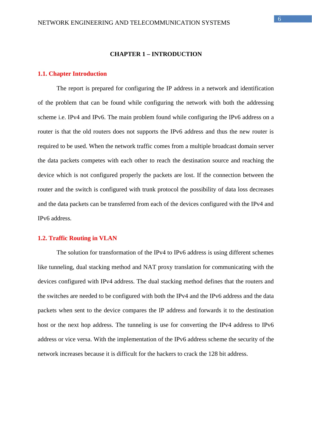
1.1. Chapter Introduction
The report is prepared for configuring the IP address in a network and identification
of the problem that can be found while configuring the network with both the addressing
scheme i.e. IPv4 and IPv6. The main problem found while configuring the IPv6 address on a
router is that the old routers does not supports the IPv6 address and thus the new router is
required to be used. When the network traffic comes from a multiple broadcast domain server
the data packets competes with each other to reach the destination source and reaching the
device which is not configured properly the packets are lost. If the connection between the
router and the switch is configured with trunk protocol the possibility of data loss decreases
and the data packets can be transferred from each of the devices configured with the IPv4 and
IPv6 address.
1.2. Traffic Routing in VLAN
The solution for transformation of the IPv4 to IPv6 address is using different schemes
like tunneling, dual stacking method and NAT proxy translation for communicating with the
devices configured with IPv4 address. The dual stacking method defines that the routers and
the switches are needed to be configured with both the IPv4 and the IPv6 address and the data
packets when sent to the device compares the IP address and forwards it to the destination
host or the next hop address. The tunneling is use for converting the IPv4 address to IPv6
address or vice versa. With the implementation of the IPv6 address scheme the security of the
network increases because it is difficult for the hackers to crack the 128 bit address.
NETWORK ENGINEERING AND TELECOMMUNICATION SYSTEMS
CHAPTER 1 – INTRODUCTION
1.1. Chapter Introduction
The report is prepared for configuring the IP address in a network and identification
of the problem that can be found while configuring the network with both the addressing
scheme i.e. IPv4 and IPv6. The main problem found while configuring the IPv6 address on a
router is that the old routers does not supports the IPv6 address and thus the new router is
required to be used. When the network traffic comes from a multiple broadcast domain server
the data packets competes with each other to reach the destination source and reaching the
device which is not configured properly the packets are lost. If the connection between the
router and the switch is configured with trunk protocol the possibility of data loss decreases
and the data packets can be transferred from each of the devices configured with the IPv4 and
IPv6 address.
1.2. Traffic Routing in VLAN
The solution for transformation of the IPv4 to IPv6 address is using different schemes
like tunneling, dual stacking method and NAT proxy translation for communicating with the
devices configured with IPv4 address. The dual stacking method defines that the routers and
the switches are needed to be configured with both the IPv4 and the IPv6 address and the data
packets when sent to the device compares the IP address and forwards it to the destination
host or the next hop address. The tunneling is use for converting the IPv4 address to IPv6
address or vice versa. With the implementation of the IPv6 address scheme the security of the
network increases because it is difficult for the hackers to crack the 128 bit address.
Paraphrase This Document
Need a fresh take? Get an instant paraphrase of this document with our AI Paraphraser
7
NETWORK ENGINEERING AND TELECOMMUNICATION SYSTEMS
1.3. Inspiration of the Project
The inspiration of the project is the recent growth of the network and increased used
of the IPv6 network for connecting with the network configured with the IPv6 address. The
VLAN is an interesting concept of a network and it reduces the cost of cabling of the network
while increasing the security for the single or multiple broadcast domain networks. The use
of DHCP in IPv6 network increases the efficiency of the network and a layer three switch can
be used for allocation of Ipv6 address to the different VLANs connected in the network. This
helps in creation of a dual stack network configuration for communicating with IPv4 as well
as IPv6 network devices.
1.4. Identification of the problem
The main problem identified in the configuration of the Ipv6 network is the regarding the
hardware because all the hardware device installed in the network does not support Ipv6
network configuration. Thus a change is required to be made in the current network solution
and new hardware should be installed for accommodation of the changes in the
organizational network. The cost of the network also increases and identification of the
broadcast domain for reconfiguration of the network acts as a barrier for the development of
the network. The interface and the sub interface of the router should be configured with the
IPv6 address for enabling the broadcast domain to communicate with the trunk line and send
and receive data packets in the network.
1.5. Solution of the Problem
The main solution for the problem is the analysis of the addressing scheme used in the current
network and creation of an IPv6 address scheme for the network for configuring the network
with dual stack mechanism. The bottleneck situation are also analyzed and a proper network
cabling plan is used for reducing the chances of packet loss or congestion in the network. The
traditional method are used for the configuration if the network and a network simulator is
8
NETWORK ENGINEERING AND TELECOMMUNICATION SYSTEMS
use for creation of a prototype of the network before implementation in the real life
environment. Separate channels are used for the connection of the different VLANS and the
unused ports are blocked for reducing the risk of unauthorized access of the network.
1.6. Aims
The aim of this project is to understand crucial implementation steps required when migrating
from IPV4 to IPV6 to ensure an effective approach and successful outcome. There is no
doubt that migrating from IPV4 to IPV6 present many benefits but equally many challenges
and issues causing delay and reluctance. Therefore, this project aim to help elaborate and
explore effective planning to overcome those challenges to deliver seamless integration and
transition as possible.
Additionally although IPV6 protocol has been around for sometimes now, there are still
knowledge gap of it, lack of skills and effective communication channel to allow businesses
and users to fully embrace it. In this project, relevant details information of IPV6 will be
provided to enhance the knowledge of it. And overview few practical deployment scenarios
and solutions to reduce misconception. Finally, at the end of this project the audience would
have gain greater confidence, substantial information, and tailored solutions to specific cases
to carry out IPV6 migration.
1.7. Objectives
The objectives of the project are aligned during the development of the project. The different
network components are analyzed and the network design is created using the cisco packet
tracer. The devices are configured with appropriate protocol and all the devices are connected
with a central server and the IPs are provided to the hosts connected to it. The network is
tested and the more devices are added with IPv6 address without changing the structure of the
network or changing the cabling plan. A power point poster and slides are created for the
⊘ This is a preview!⊘
Do you want full access?
Subscribe today to unlock all pages.
Trusted by 1+ million students worldwide
9
NETWORK ENGINEERING AND TELECOMMUNICATION SYSTEMS
demonstration of the proper working of the project. The main objective of the project are as
follows:
1. Analyse the difference between IPV4 and IPV6
2. Understand IPV6 Protocols and standards
3. Explore potential challenges and issues during migration
4. Understand crucial implementation steps
5. Elaborate appropriate strategies and planning approach
6. Provide deployment scenario and practical tailored solutions
1.8. Records of risk, constraints and assumptions
It is assumed that for the development of the project different barriers would arise and
it should be overcome for making the project a success. The risk should be identified in the
early stages of the development of the project for creation of a risk mitigation strategy and
simulation is done for the configuration of the network and identify the errors in the network.
The hardware used in the network should be available and it should be compatible with the
other hardware device connected in the network. The constraint acting for the development of
the network solution the inefficient knowledge about the IPv6 address and it should be
improved for developing the network accordingly. The time also acts as a risk and the project
should be completed within the given time for the success of the project. The IPv6 uses 128
bit addressing whereas IPv4 uses 32 bit address and thus have the limitation to accommodate
the growing number of devices in the network. Different protocols and techniques are used
for the transformation of the Ipv4 with the IPv6 address without affecting the network and for
increasing the efficiency of the network. The proper configuration of the router and the end
devices are necessary for the implementation of the IPv6 address scheme in an old network
currently running using the IPv4 addressing. The implementation of the IPv6 helps to
increase the address space of the network but there is as requirement of proper sub netting for
Paraphrase This Document
Need a fresh take? Get an instant paraphrase of this document with our AI Paraphraser
10
NETWORK ENGINEERING AND TELECOMMUNICATION SYSTEMS
reducing the wastage of the IP address. A verification must be done on the network where the
IPv6 addressing is required to be implemented because all the devices are not capable to run
using the IPv6 address as they were designed for IPv4 address.
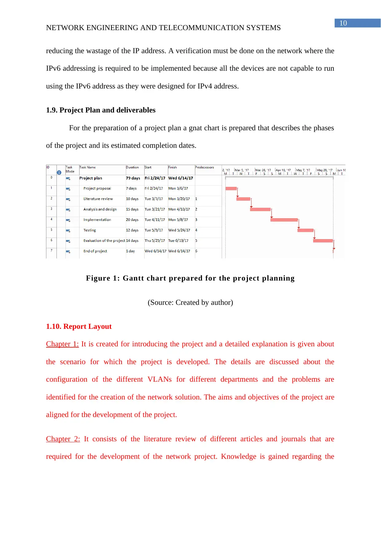
1.9. Project Plan and deliverables
For the preparation of a project plan a gnat chart is prepared that describes the phases
of the project and its estimated completion dates.
Figure 1: Gantt chart prepared for the project planning
(Source: Created by author)
1.10. Report Layout
Chapter 1: It is created for introducing the project and a detailed explanation is given about
the scenario for which the project is developed. The details are discussed about the
configuration of the different VLANs for different departments and the problems are
identified for the creation of the network solution. The aims and objectives of the project are
aligned for the development of the project.
Chapter 2: It consists of the literature review of different articles and journals that are
required for the development of the network project. Knowledge is gained regarding the
NETWORK ENGINEERING AND TELECOMMUNICATION SYSTEMS
reducing the wastage of the IP address. A verification must be done on the network where the
IPv6 addressing is required to be implemented because all the devices are not capable to run
using the IPv6 address as they were designed for IPv4 address.
1.9. Project Plan and deliverables
For the preparation of a project plan a gnat chart is prepared that describes the phases
of the project and its estimated completion dates.
Figure 1: Gantt chart prepared for the project planning
(Source: Created by author)
1.10. Report Layout
Chapter 1: It is created for introducing the project and a detailed explanation is given about
the scenario for which the project is developed. The details are discussed about the
configuration of the different VLANs for different departments and the problems are
identified for the creation of the network solution. The aims and objectives of the project are
aligned for the development of the project.
Chapter 2: It consists of the literature review of different articles and journals that are
required for the development of the network project. Knowledge is gained regarding the
11
NETWORK ENGINEERING AND TELECOMMUNICATION SYSTEMS
concept of VLAN and the advantage or disadvantage of using different networking protocols
for the security of the network is discussed.
Chapter 3: The main focus of the chapter is on the designing and analysis of the different
network components for the development of the network infrastructure. The selection of the
hardware components and the coverage area of the network is discussed for the development
of the network.
Chapter 4: This chapter discusses about the stage involved in the implementation of the
project and configuring the network according to the aims and objectives of the project. The
network configuration and the hardware used are listed.
Chapter 5: In this chapter the details of the test cases and the test performed on the network
are given.
Chapter 6: Here the project is concluded after a detailed evaluation of the working of the
project.
1.11. Summary
The project of ‘IPV6 – Migration Study from IPv4 and IPv6’ started with the creation of the
project proposal and the project plan. A literature review is done for understanding the
working principle of IPV6 protocol and standards to allow the implementation IPV6 address
in a network. The use of the hardware devices, software version, as well as license are
essential for configuring the IPV6 and implement its full benefits. Layer 2 and the layer 3
switches are also analyzed for creation of the report and performing the practical operation.
Cisco packet tracer is used for configuring the devices and finding the flaws in the network
when more data is generated in the network. The routers and the switches are configured with
⊘ This is a preview!⊘
Do you want full access?
Subscribe today to unlock all pages.
Trusted by 1+ million students worldwide
1 out of 44
Related Documents


Your All-in-One AI-Powered Toolkit for Academic Success.
+13062052269
info@desklib.com
Available 24*7 on WhatsApp / Email
![[object Object]](/_next/static/media/star-bottom.7253800d.svg)
Unlock your academic potential
Copyright © 2020–2026 A2Z Services. All Rights Reserved. Developed and managed by ZUCOL.