Systems Architecture Definition Report for ISYS1088 Assignment 1
VerifiedAdded on 2023/04/08
|25
|2697
|134
Report
AI Summary
This report presents the Solution Architecture Definition for the ACME Business Banking Online System, submitted as Assignment 1 for the RMIT ISYS1088-89 course. It encompasses the requirements, functional, and operational viewpoints. The document outlines functional and non-functional requirements, including a summary of conflicting requirements. It defines users, actors, and the system context, providing an architecture overview and detailed component models, interaction diagrams, and component interfaces. The report further explores the deployment viewpoint, including logical locations, deployment units, and logical and physical operational views. Architectural change cases and assumptions are also addressed. The assignment covers the core architectural viewpoints, providing a comprehensive understanding of the system's design and implementation. The report also provides details about the functional requirements such as allowing customers to view accounts, make payments, and download statements. Non-functional requirements include timelines, external IT service providers, and system capacity. The architecture overview includes major components like databases, customers, and approvers, and external resources like the ACME head office and internet service providers. The report highlights the use of an external server to reduce infrastructure costs. The assignment also includes Architectural Decision AD0129, focusing on the implementation of value transactions, outlining the problem statement, motivation, assumptions, alternative options, decision, implications, and derived requirements.
Systems Architecture
Assignment 1: Solution Architecture Definition
Template
Version: 1.02 Issued: Status: Document ID:
Internal Use Only
Assignment 1: Solution Architecture Definition
Template
Version: 1.02 Issued: Status: Document ID:
Internal Use Only
Paraphrase This Document
Need a fresh take? Get an instant paraphrase of this document with our AI Paraphraser
ISYS1088-89: SYSTEMS ARCHITECTURE
Document control
Title Assignment 1 - Solution Architecture Definition
Contact(s) for inquiries and proposed changes
For information regarding this document or if you have any questions or suggestions regarding the content, please contact
the following:
Name Title
Change history
Version Date Revised by Brief outline of changes
1.00 22 February 2019 <Your name here> Initial version
Approval or Sign off
Name Title
ASSIGNMENT 1: SOLUTION ARCHITECTURE DEFINITION Page 2 of 25
ISYS1088-89: SYSTEMS ARCHITECTURE
Table of Contents
1 Introduction...................................................................................................................................4
1.1 Purpose of this document....................................................................................................4
1.2 List of acronyms...................................................................................................................4
1.3 References and related documents......................................................................................4
2 Overview of requirements.............................................................................................................5
2.1 Summary of functional requirements..................................................................................5
2.2 Summary of non-functional requirements...........................................................................5
2.3 Out of scope statements......................................................................................................6
3 Users, Actors and System Context.................................................................................................7
3.1 Human users, actors and their location................................................................................7
3.2 System users (Non-human users).........................................................................................7
4 Architecture overview...................................................................................................................8
5 Functional viewpoint: Component model...................................................................................11
5.1 Component relationship diagram.......................................................................................11
5.2 Interaction diagrams..........................................................................................................13
5.3 Component interfaces........................................................................................................15
6 Deployment (Operational) Viewpoint..........................................................................................16
6.1 Logical Locations View........................................................................................................16
6.2 Deployment Unit View.......................................................................................................17
6.3 Logical Operational View....................................................................................................17
6.4 Physical Operational View..................................................................................................18
6.4.1 Location: <Location 1>..................................................................................................20
6.4.2 Location: <Location 2>..................................................................................................20
7 Architectural change cases..........................................................................................................21
8 Assumptions................................................................................................................................22
ASSIGNMENT 1: SOLUTION ARCHITECTURE DEFINITION Page 3 of 25
⊘ This is a preview!⊘
Do you want full access?
Subscribe today to unlock all pages.
Trusted by 1+ million students worldwide
ISYS1088-89: SYSTEMS ARCHITECTURE
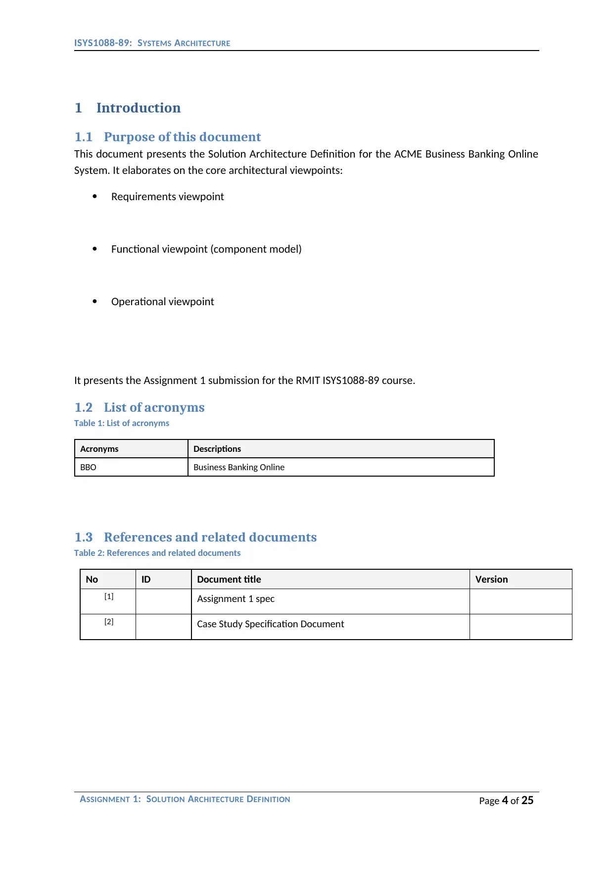
1 Introduction
1.1 Purpose of this document
This document presents the Solution Architecture Definition for the ACME Business Banking Online
System. It elaborates on the core architectural viewpoints:
Requirements viewpoint
Functional viewpoint (component model)
Operational viewpoint
It presents the Assignment 1 submission for the RMIT ISYS1088-89 course.
1.2 List of acronyms
Table 1: List of acronyms
Acronyms Descriptions
BBO Business Banking Online
1.3 References and related documents
Table 2: References and related documents
No ID Document title Version
[1] Assignment 1 spec
[2] Case Study Specification Document
ASSIGNMENT 1: SOLUTION ARCHITECTURE DEFINITION Page 4 of 25
Paraphrase This Document
Need a fresh take? Get an instant paraphrase of this document with our AI Paraphraser
ISYS1088-89: SYSTEMS ARCHITECTURE
2 Overview of requirements
2.1 Summary of functional requirements
<Present here your concise summary of Functional Requirements. Keep it under 2 pages>
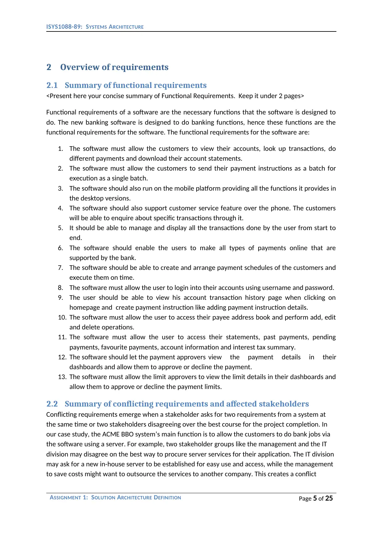
Functional requirements of a software are the necessary functions that the software is designed to
do. The new banking software is designed to do banking functions, hence these functions are the
functional requirements for the software. The functional requirements for the software are:
1. The software must allow the customers to view their accounts, look up transactions, do
different payments and download their account statements.
2. The software must allow the customers to send their payment instructions as a batch for
execution as a single batch.
3. The software should also run on the mobile platform providing all the functions it provides in
the desktop versions.
4. The software should also support customer service feature over the phone. The customers
will be able to enquire about specific transactions through it.
5. It should be able to manage and display all the transactions done by the user from start to
end.
6. The software should enable the users to make all types of payments online that are
supported by the bank.
7. The software should be able to create and arrange payment schedules of the customers and
execute them on time.
8. The software must allow the user to login into their accounts using username and password.
9. The user should be able to view his account transaction history page when clicking on
homepage and create payment instruction like adding payment instruction details.
10. The software must allow the user to access their payee address book and perform add, edit
and delete operations.
11. The software must allow the user to access their statements, past payments, pending
payments, favourite payments, account information and interest tax summary.
12. The software should let the payment approvers view the payment details in their
dashboards and allow them to approve or decline the payment.
13. The software must allow the limit approvers to view the limit details in their dashboards and
allow them to approve or decline the payment limits.
2.2 Summary of conflicting requirements and affected stakeholders
Conflicting requirements emerge when a stakeholder asks for two requirements from a system at
the same time or two stakeholders disagreeing over the best course for the project completion. In
our case study, the ACME BBO system’s main function is to allow the customers to do bank jobs via
the software using a server. For example, two stakeholder groups like the management and the IT
division may disagree on the best way to procure server services for their application. The IT division
may ask for a new in-house server to be established for easy use and access, while the management
to save costs might want to outsource the services to another company. This creates a conflict
ASSIGNMENT 1: SOLUTION ARCHITECTURE DEFINITION Page 5 of 25
2 Overview of requirements
2.1 Summary of functional requirements
<Present here your concise summary of Functional Requirements. Keep it under 2 pages>
Functional requirements of a software are the necessary functions that the software is designed to
do. The new banking software is designed to do banking functions, hence these functions are the
functional requirements for the software. The functional requirements for the software are:
1. The software must allow the customers to view their accounts, look up transactions, do
different payments and download their account statements.
2. The software must allow the customers to send their payment instructions as a batch for
execution as a single batch.
3. The software should also run on the mobile platform providing all the functions it provides in
the desktop versions.
4. The software should also support customer service feature over the phone. The customers
will be able to enquire about specific transactions through it.
5. It should be able to manage and display all the transactions done by the user from start to
end.
6. The software should enable the users to make all types of payments online that are
supported by the bank.
7. The software should be able to create and arrange payment schedules of the customers and
execute them on time.
8. The software must allow the user to login into their accounts using username and password.
9. The user should be able to view his account transaction history page when clicking on
homepage and create payment instruction like adding payment instruction details.
10. The software must allow the user to access their payee address book and perform add, edit
and delete operations.
11. The software must allow the user to access their statements, past payments, pending
payments, favourite payments, account information and interest tax summary.
12. The software should let the payment approvers view the payment details in their
dashboards and allow them to approve or decline the payment.
13. The software must allow the limit approvers to view the limit details in their dashboards and
allow them to approve or decline the payment limits.
2.2 Summary of conflicting requirements and affected stakeholders
Conflicting requirements emerge when a stakeholder asks for two requirements from a system at
the same time or two stakeholders disagreeing over the best course for the project completion. In
our case study, the ACME BBO system’s main function is to allow the customers to do bank jobs via
the software using a server. For example, two stakeholder groups like the management and the IT
division may disagree on the best way to procure server services for their application. The IT division
may ask for a new in-house server to be established for easy use and access, while the management
to save costs might want to outsource the services to another company. This creates a conflict
ASSIGNMENT 1: SOLUTION ARCHITECTURE DEFINITION Page 5 of 25
ISYS1088-89: SYSTEMS ARCHITECTURE
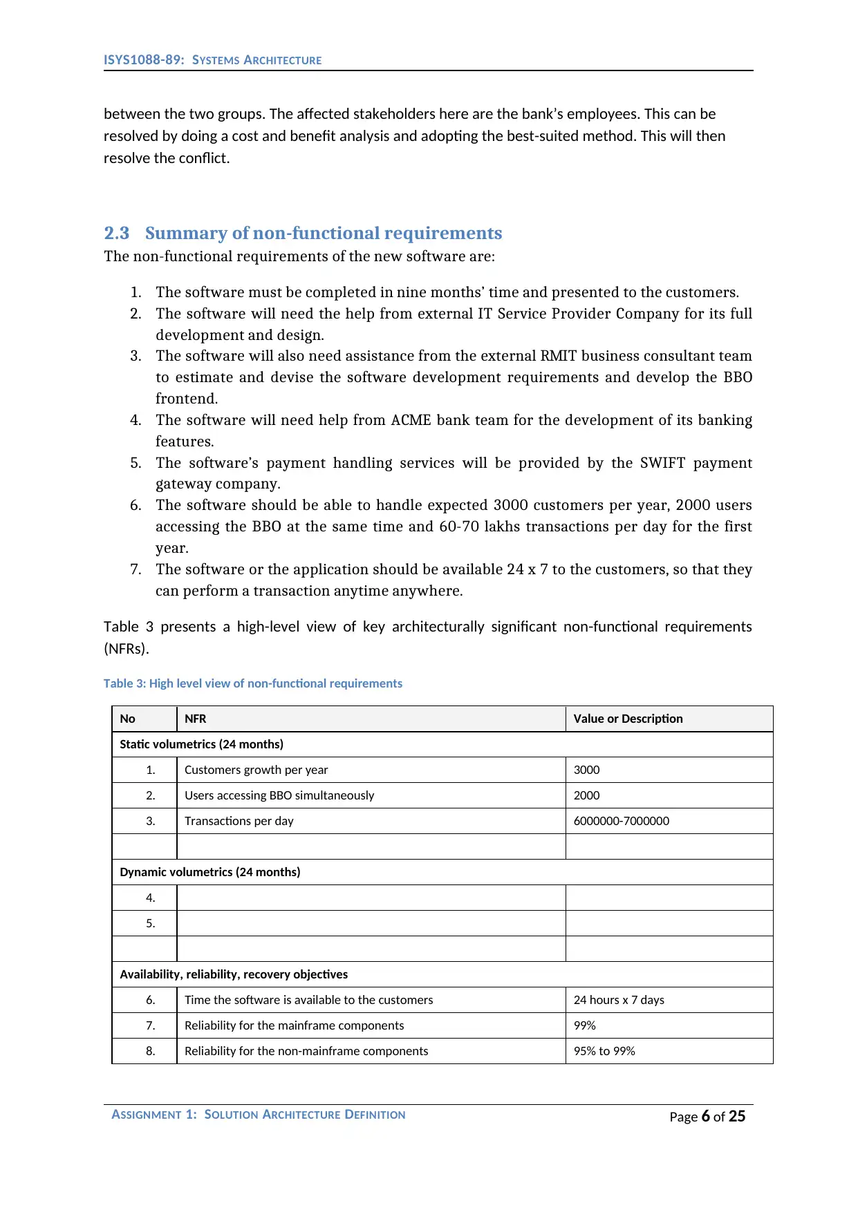
between the two groups. The affected stakeholders here are the bank’s employees. This can be
resolved by doing a cost and benefit analysis and adopting the best-suited method. This will then
resolve the conflict.
2.3 Summary of non-functional requirements
The non-functional requirements of the new software are:
1. The software must be completed in nine months’ time and presented to the customers.
2. The software will need the help from external IT Service Provider Company for its full
development and design.
3. The software will also need assistance from the external RMIT business consultant team
to estimate and devise the software development requirements and develop the BBO
frontend.
4. The software will need help from ACME bank team for the development of its banking
features.
5. The software’s payment handling services will be provided by the SWIFT payment
gateway company.
6. The software should be able to handle expected 3000 customers per year, 2000 users
accessing the BBO at the same time and 60-70 lakhs transactions per day for the first
year.
7. The software or the application should be available 24 x 7 to the customers, so that they
can perform a transaction anytime anywhere.
Table 3 presents a high-level view of key architecturally significant non-functional requirements
(NFRs).
Table 3: High level view of non-functional requirements
No NFR Value or Description
Static volumetrics (24 months)
1. Customers growth per year 3000
2. Users accessing BBO simultaneously 2000
3. Transactions per day 6000000-7000000
Dynamic volumetrics (24 months)
4.
5.
Availability, reliability, recovery objectives
6. Time the software is available to the customers 24 hours x 7 days
7. Reliability for the mainframe components 99%
8. Reliability for the non-mainframe components 95% to 99%
ASSIGNMENT 1: SOLUTION ARCHITECTURE DEFINITION Page 6 of 25
⊘ This is a preview!⊘
Do you want full access?
Subscribe today to unlock all pages.
Trusted by 1+ million students worldwide
ISYS1088-89: SYSTEMS ARCHITECTURE
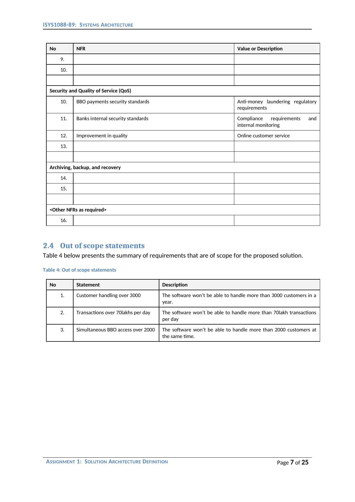
No NFR Value or Description
9.
10.
Security and Quality of Service (QoS)
10. BBO payments security standards Anti-money laundering regulatory
requirements
11. Banks internal security standards Compliance requirements and
internal monitoring
12. Improvement in quality Online customer service
13.
Archiving, backup, and recovery
14.
15.
<Other NFRs as required>
16.
2.4 Out of scope statements
Table 4 below presents the summary of requirements that are of scope for the proposed solution.
Table 4: Out of scope statements
No Statement Description
1. Customer handling over 3000 The software won’t be able to handle more than 3000 customers in a
year.
2. Transactions over 70lakhs per day The software won’t be able to handle more than 70lakh transactions
per day
3. Simultaneous BBO access over 2000 The software won’t be able to handle more than 2000 customers at
the same time.
ASSIGNMENT 1: SOLUTION ARCHITECTURE DEFINITION Page 7 of 25
Paraphrase This Document
Need a fresh take? Get an instant paraphrase of this document with our AI Paraphraser
ISYS1088-89: SYSTEMS ARCHITECTURE
3 Users, Actors and System Context
This section defines the target users and actors for the ACME Business Banking Online System (BBO).
The main target users of the ACME Business Banking Online System or BBO are the corporate
companies and the individual customers of the bank. These companies have accounts and
transactions that are maintained and handled by the bank and the individual customers include
people who have accounts in that bank.
3.1 Human users, actors and their location
<What are the human users and actors that will be using the system?>
The human users and actors using the system are:
1. Normal users that includes the corporate company clients and individual person clients.
2. Limit approvers are bank employees who set the payment limits for the clients.
3. Payment approvers are the bank employees who allow or decline the payments of the
clients.
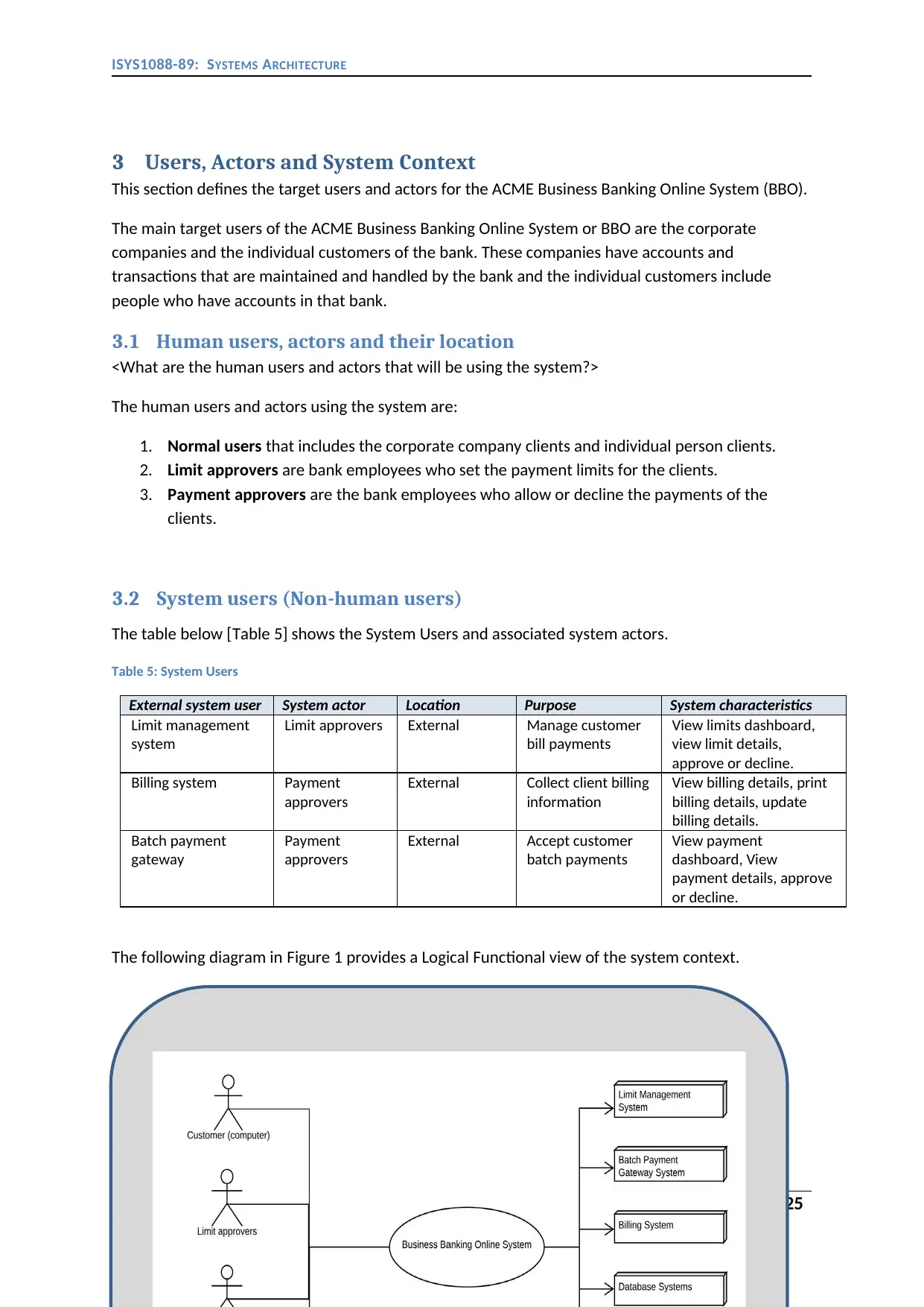
3.2 System users (Non-human users)
The table below [Table 5] shows the System Users and associated system actors.
Table 5: System Users
External system user System actor Location Purpose System characteristics
Limit management
system
Limit approvers External Manage customer
bill payments
View limits dashboard,
view limit details,
approve or decline.
Billing system Payment
approvers
External Collect client billing
information
View billing details, print
billing details, update
billing details.
Batch payment
gateway
Payment
approvers
External Accept customer
batch payments
View payment
dashboard, View
payment details, approve
or decline.
The following diagram in Figure 1 provides a Logical Functional view of the system context.
ASSIGNMENT 1: SOLUTION ARCHITECTURE DEFINITION Page 8 of 25
3 Users, Actors and System Context
This section defines the target users and actors for the ACME Business Banking Online System (BBO).
The main target users of the ACME Business Banking Online System or BBO are the corporate
companies and the individual customers of the bank. These companies have accounts and
transactions that are maintained and handled by the bank and the individual customers include
people who have accounts in that bank.
3.1 Human users, actors and their location
<What are the human users and actors that will be using the system?>
The human users and actors using the system are:
1. Normal users that includes the corporate company clients and individual person clients.
2. Limit approvers are bank employees who set the payment limits for the clients.
3. Payment approvers are the bank employees who allow or decline the payments of the
clients.
3.2 System users (Non-human users)
The table below [Table 5] shows the System Users and associated system actors.
Table 5: System Users
External system user System actor Location Purpose System characteristics
Limit management
system
Limit approvers External Manage customer
bill payments
View limits dashboard,
view limit details,
approve or decline.
Billing system Payment
approvers
External Collect client billing
information
View billing details, print
billing details, update
billing details.
Batch payment
gateway
Payment
approvers
External Accept customer
batch payments
View payment
dashboard, View
payment details, approve
or decline.
The following diagram in Figure 1 provides a Logical Functional view of the system context.
ASSIGNMENT 1: SOLUTION ARCHITECTURE DEFINITION Page 8 of 25
ISYS1088-89: SYSTEMS ARCHITECTURE
Figure 1: System Context diagram
ASSIGNMENT 1: SOLUTION ARCHITECTURE DEFINITION Page 9 of 25
Figure 1: System Context diagram
ASSIGNMENT 1: SOLUTION ARCHITECTURE DEFINITION Page 9 of 25
⊘ This is a preview!⊘
Do you want full access?
Subscribe today to unlock all pages.
Trusted by 1+ million students worldwide

ISYS1088-89: SYSTEMS ARCHITECTURE
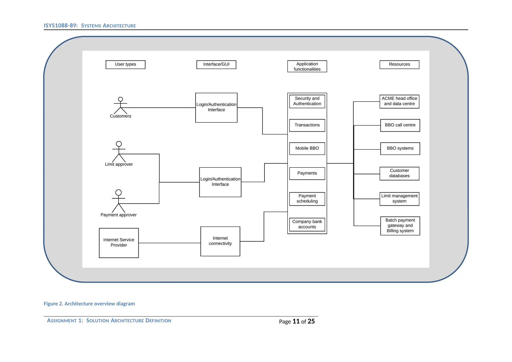
4 Architecture overview
The architecture overview for the ACME Business Banking Online System (BBO) is shown in Figure 2.
The architectural overview of a system mainly defines the various fundamental components of the
system and how they interact with each other and the environment. The system may have multiple
components and it may require different external services to manage and operate smoothly. The
major components in this Business Banking Online or BBO are the databases that store the customer
information, the customers that operate the application, the limit and payment approvers who work
for the bank, the transactions and payment scheduling functions, the mobile platform version of
the system, the company bank account archives and the security and authentication systems. The
externally used resources that are essential for the system’s proper functioning includes the ACME
head office and data centre, the BBO call centre, the BBO systems, the system databases, the limit
management system, the batch payment gateway and billing systems. These external systems are
responsible for providing the system with the data that it needs to process the various transaction
requests. The limit and payment approvers are the bank employees who are responsible for the
approvals and processing of the transaction requests that are initiated by the customers. The
customers include both corporate and individual customers who have individual or employee
accounts with the bank. The internet service providers are the external agencies that are used by
the customers to access the application on their mobiles or computers. These companies provide
the user with internet connectivity that enables them to access the authentication servers and use
the various functions of the software. The architecture overview diagram also shows us the internal
and external view of the system in one single place. The functions of the system, the external
agencies involved with it, the customers or users of the BBO all together complete the whole
architecture of the system. The architecture overview diagram given in this report represents an
enterprise view of the system given in the case study.
The architectural decisions made for this project is the use of an external server. This
external server reduces infrastructure cost for the company. The server is an integral part of running
any online database driven system. The outsourcing of the server to an external company will reduce
the company’s cost on server maintenance and hardware purchase. This saved amount can be used
to invest elsewhere. The functions performed by the system like transactions, payments,
authentication, limit and payment approving are all depended on the server. The server is the only
part of the system that is being used constantly and hence need a 24-hour maintenance team. The
whole system shown in this case study is a server based application and hence its functional
requirements are all depended on the architectural decision made.
ASSIGNMENT 1: SOLUTION ARCHITECTURE DEFINITION Page 10 of 25
Paraphrase This Document
Need a fresh take? Get an instant paraphrase of this document with our AI Paraphraser
ISYS1088-89: SYSTEMS ARCHITECTURE
Figure 2. Architecture overview diagram
ASSIGNMENT 1: SOLUTION ARCHITECTURE DEFINITION Page 11 of 25
Figure 2. Architecture overview diagram
ASSIGNMENT 1: SOLUTION ARCHITECTURE DEFINITION Page 11 of 25
ISYS1088-89: SYSTEMS ARCHITECTURE
.
ASSIGNMENT 1: SOLUTION ARCHITECTURE DEFINITION Page 12 of 25
.
ASSIGNMENT 1: SOLUTION ARCHITECTURE DEFINITION Page 12 of 25
⊘ This is a preview!⊘
Do you want full access?
Subscribe today to unlock all pages.
Trusted by 1+ million students worldwide
1 out of 25
Related Documents


Your All-in-One AI-Powered Toolkit for Academic Success.
+13062052269
info@desklib.com
Available 24*7 on WhatsApp / Email
![[object Object]](/_next/static/media/star-bottom.7253800d.svg)
Unlock your academic potential
Copyright © 2020–2026 A2Z Services. All Rights Reserved. Developed and managed by ZUCOL.