IT Fundamentals Assignment: Architecture, Number Systems, MARIE
VerifiedAdded on 2022/09/01
|15
|1476
|54
Homework Assignment
AI Summary
This assignment solution covers several core concepts in IT fundamentals. The first question discusses the fundamental architecture of computers, specifically the stored-program architecture (Von Neumann architecture), and Moore's Law. The second question delves into binary number systems, exploring signed magnitude, one's complement, and two's complement representations, along with their decimal equivalents, and IEEE 754 floating-point format. The third question focuses on assembly language and the MARIE (Machine Architecture that is Really Intuitive and Educational) computer architecture, providing MARIE assembly code to calculate a sum and a program for basic statistics. The solution includes example outputs and explanations of the code's functionality and register usage.
Running head: IT FUNDAMENTALS
IT FUNDAMENTALS
Name of the Student
Name of the University
Author Note
IT FUNDAMENTALS
Name of the Student
Name of the University
Author Note
Paraphrase This Document
Need a fresh take? Get an instant paraphrase of this document with our AI Paraphraser
1IT FUNDAMENTALS
Question 1:
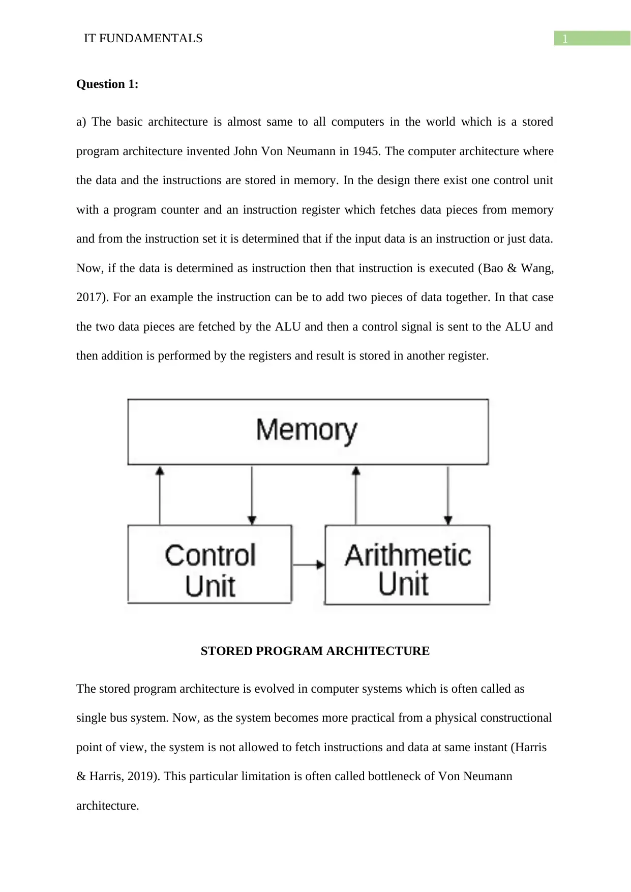
a) The basic architecture is almost same to all computers in the world which is a stored
program architecture invented John Von Neumann in 1945. The computer architecture where
the data and the instructions are stored in memory. In the design there exist one control unit
with a program counter and an instruction register which fetches data pieces from memory
and from the instruction set it is determined that if the input data is an instruction or just data.
Now, if the data is determined as instruction then that instruction is executed (Bao & Wang,
2017). For an example the instruction can be to add two pieces of data together. In that case
the two data pieces are fetched by the ALU and then a control signal is sent to the ALU and
then addition is performed by the registers and result is stored in another register.
STORED PROGRAM ARCHITECTURE
The stored program architecture is evolved in computer systems which is often called as
single bus system. Now, as the system becomes more practical from a physical constructional
point of view, the system is not allowed to fetch instructions and data at same instant (Harris
& Harris, 2019). This particular limitation is often called bottleneck of Von Neumann
architecture.
2IT FUNDAMENTALS
b)
The Moore’s law states that as the computational efficiency and capability of computers
expected to double in every two years, the number of transistors in a microchip will also
increase proportionally. This law is the technological benchmark of the semiconductor
industry as with this law the industries set up predictive roadmap of technological
manufacturing which spanned nearly 1971 to 2020. Also, all the industries plans their future
software releases based on the Moore’s law technical window (Waldrop, 2016).
Economically, this law is also useful in the future as all the modern computing devices tend
to show exponential complexity growth and power of computing with reduced cost to the
consumers and manufacturer. Although, the actual growth of computational complexity is
found to get more than double in two years in recent time, the industries still can make the
approximate forecast of budget in the next 2 years to plan accordingly with product
promotions.
Question 2:
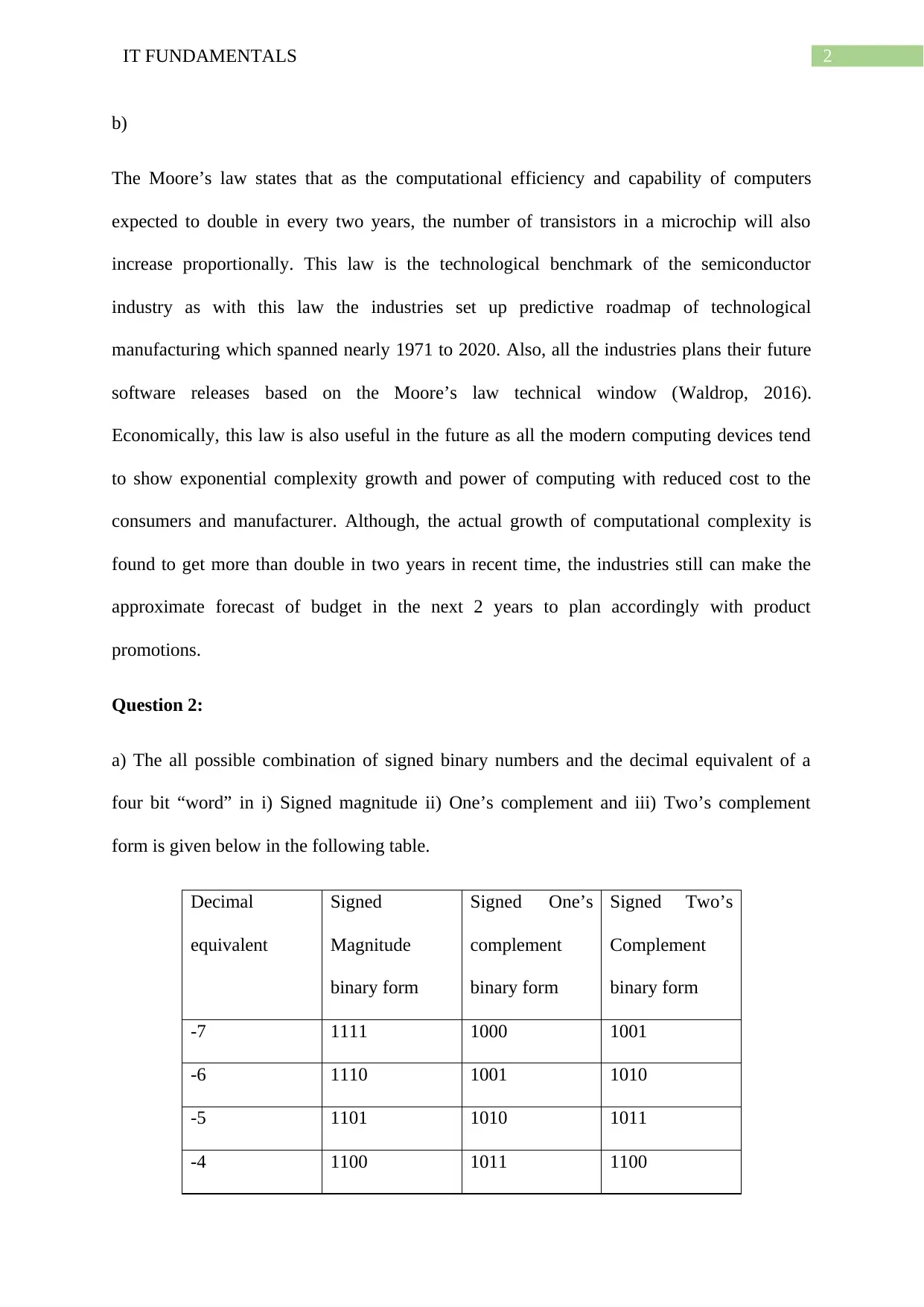
a) The all possible combination of signed binary numbers and the decimal equivalent of a
four bit “word” in i) Signed magnitude ii) One’s complement and iii) Two’s complement
form is given below in the following table.
Decimal
equivalent
Signed
Magnitude
binary form
Signed One’s
complement
binary form
Signed Two’s
Complement
binary form
-7 1111 1000 1001
-6 1110 1001 1010
-5 1101 1010 1011
-4 1100 1011 1100
⊘ This is a preview!⊘
Do you want full access?
Subscribe today to unlock all pages.

Trusted by 1+ million students worldwide
3IT FUNDAMENTALS
-3 1011 1100 1101
-2 1010 1101 1110
-1 1001 1110 1111
+0 0000 0000 -
-0 1000 1111 0000
1 0001 0001 0001
2 0010 0010 0010
3 0011 0011 0011
4 0100 0100 0100
5 0101 0101 0101
6 0110 0110 0110
7 0111 0111 0111
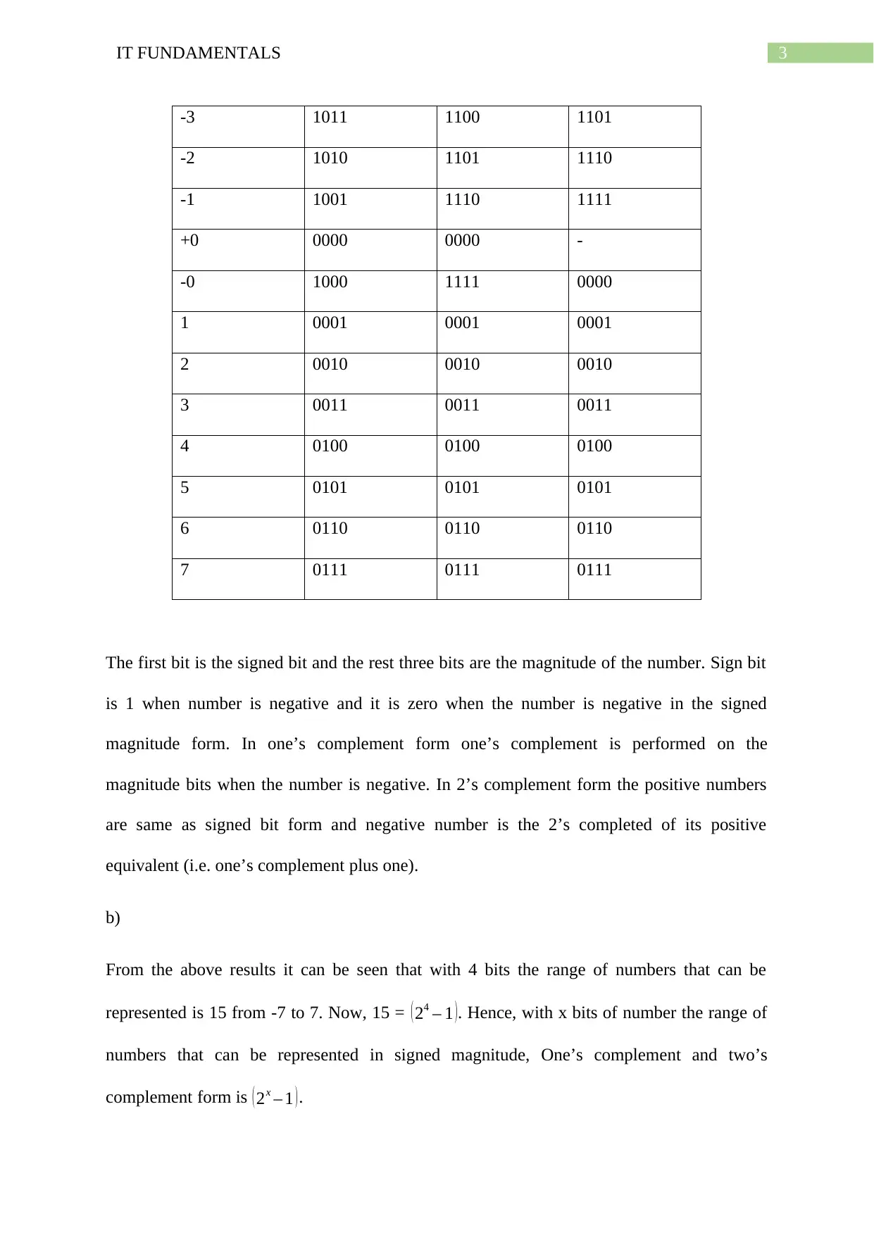
The first bit is the signed bit and the rest three bits are the magnitude of the number. Sign bit
is 1 when number is negative and it is zero when the number is negative in the signed
magnitude form. In one’s complement form one’s complement is performed on the
magnitude bits when the number is negative. In 2’s complement form the positive numbers
are same as signed bit form and negative number is the 2’s completed of its positive
equivalent (i.e. one’s complement plus one).
b)
From the above results it can be seen that with 4 bits the range of numbers that can be
represented is 15 from -7 to 7. Now, 15 = ( 24 – 1 ). Hence, with x bits of number the range of
numbers that can be represented in signed magnitude, One’s complement and two’s
complement form is ( 2x – 1 ).
Paraphrase This Document
Need a fresh take? Get an instant paraphrase of this document with our AI Paraphraser
4IT FUNDAMENTALS
c)
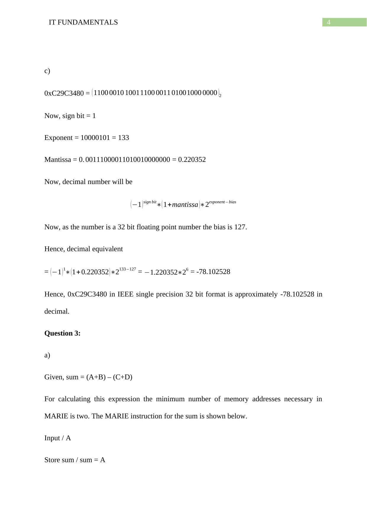
0xC29C3480 = ( 1100 0010 10011100 0011 01001000 0000 )2
Now, sign bit = 1
Exponent = 10000101 = 133
Mantissa = 0. 00111000011010010000000 = 0.220352
Now, decimal number will be
( −1 ) sign bit∗( 1+mantissa )∗2exponent – bias
Now, as the number is a 32 bit floating point number the bias is 127.
Hence, decimal equivalent
= ( −1 ) 1∗ ( 1+0.220352 ) ∗2133 – 127 = −1.220352∗26 = -78.102528
Hence, 0xC29C3480 in IEEE single precision 32 bit format is approximately -78.102528 in
decimal.
Question 3:
a)
Given, sum = (A+B) – (C+D)
For calculating this expression the minimum number of memory addresses necessary in
MARIE is two. The MARIE instruction for the sum is shown below.
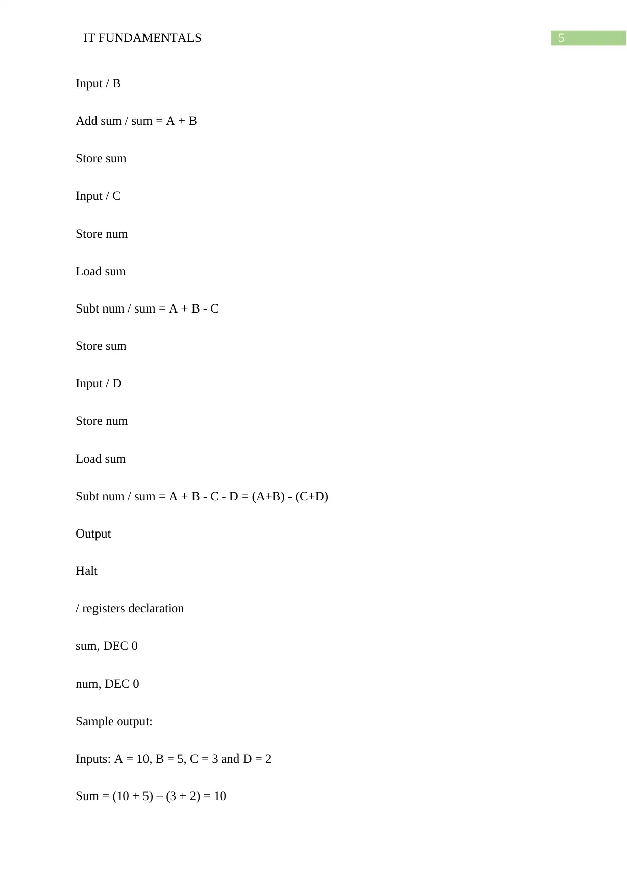
Input / A
Store sum / sum = A
5IT FUNDAMENTALS
Input / B
Add sum / sum = A + B
Store sum
Input / C
Store num
Load sum
Subt num / sum = A + B - C
Store sum
Input / D
Store num
Load sum
Subt num / sum = A + B - C - D = (A+B) - (C+D)
Output
Halt
/ registers declaration
sum, DEC 0
num, DEC 0
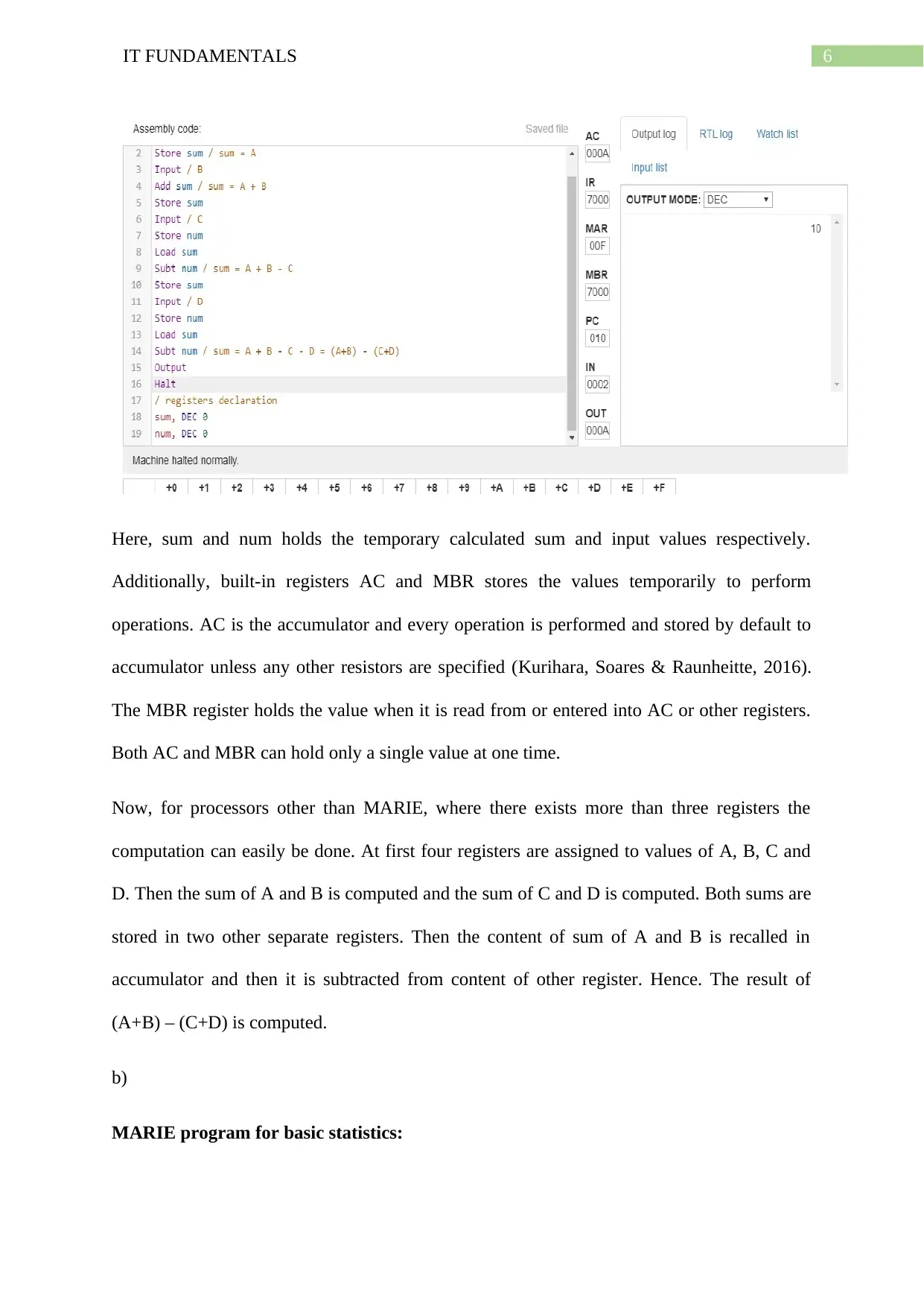
Sample output:
Inputs: A = 10, B = 5, C = 3 and D = 2
Sum = (10 + 5) – (3 + 2) = 10
⊘ This is a preview!⊘
Do you want full access?
Subscribe today to unlock all pages.

Trusted by 1+ million students worldwide
6IT FUNDAMENTALS
Here, sum and num holds the temporary calculated sum and input values respectively.
Additionally, built-in registers AC and MBR stores the values temporarily to perform
operations. AC is the accumulator and every operation is performed and stored by default to
accumulator unless any other resistors are specified (Kurihara, Soares & Raunheitte, 2016).
The MBR register holds the value when it is read from or entered into AC or other registers.
Both AC and MBR can hold only a single value at one time.
Now, for processors other than MARIE, where there exists more than three registers the
computation can easily be done. At first four registers are assigned to values of A, B, C and
D. Then the sum of A and B is computed and the sum of C and D is computed. Both sums are
stored in two other separate registers. Then the content of sum of A and B is recalled in
accumulator and then it is subtracted from content of other register. Hence. The result of
(A+B) – (C+D) is computed.
b)
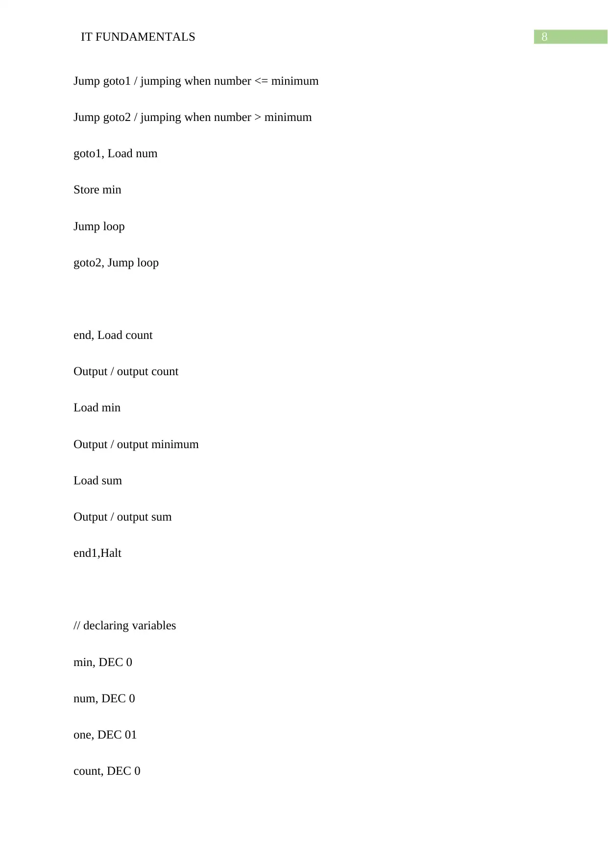
MARIE program for basic statistics:
Paraphrase This Document
Need a fresh take? Get an instant paraphrase of this document with our AI Paraphraser
7IT FUNDAMENTALS
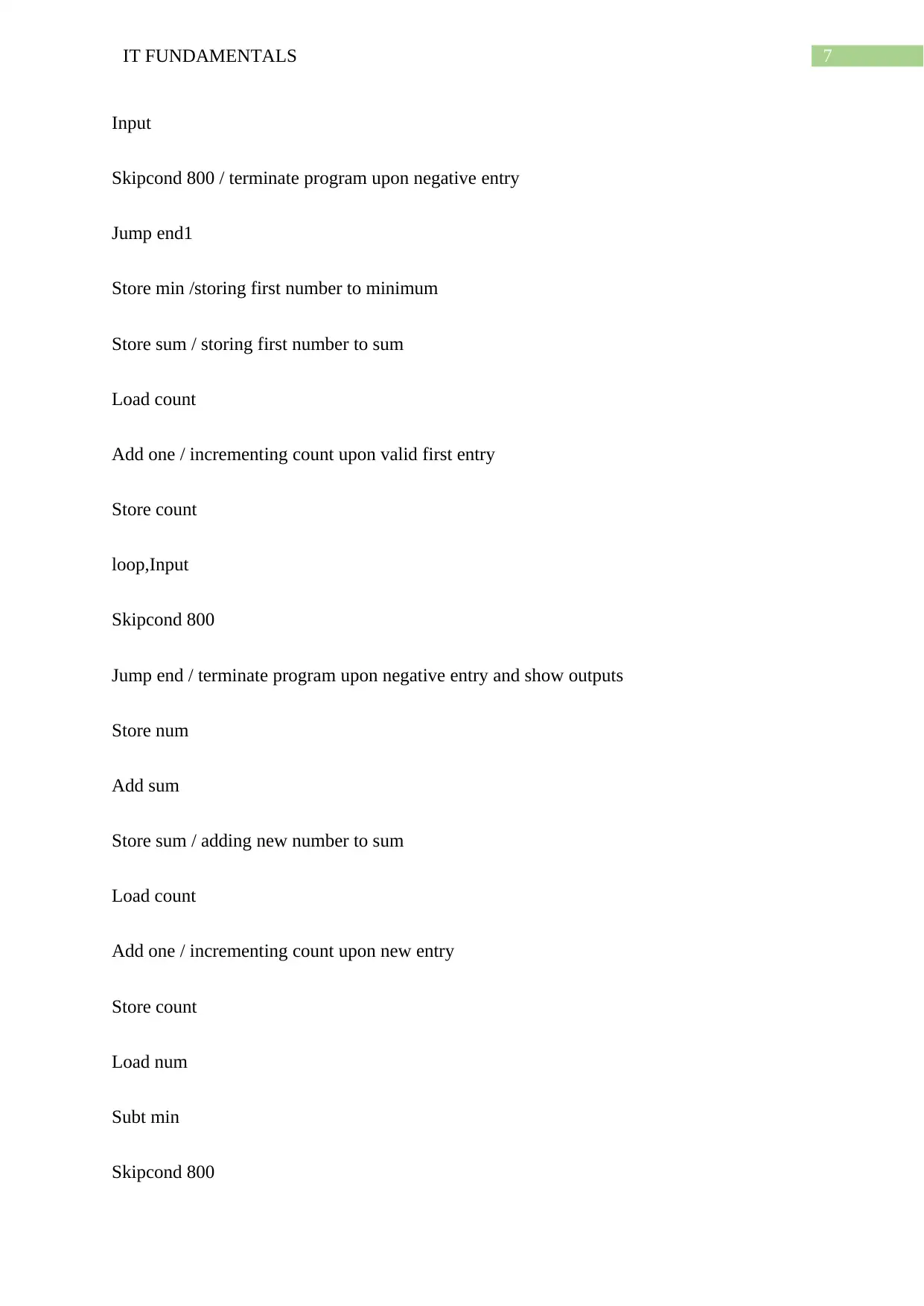
Input
Skipcond 800 / terminate program upon negative entry
Jump end1
Store min /storing first number to minimum
Store sum / storing first number to sum
Load count
Add one / incrementing count upon valid first entry
Store count
loop,Input
Skipcond 800
Jump end / terminate program upon negative entry and show outputs
Store num
Add sum
Store sum / adding new number to sum
Load count
Add one / incrementing count upon new entry
Store count
Load num
Subt min
Skipcond 800
8IT FUNDAMENTALS
Jump goto1 / jumping when number <= minimum
Jump goto2 / jumping when number > minimum
goto1, Load num
Store min
Jump loop
goto2, Jump loop
end, Load count
Output / output count
Load min
Output / output minimum
Load sum
Output / output sum
end1,Halt
// declaring variables
min, DEC 0
num, DEC 0
one, DEC 01
count, DEC 0
⊘ This is a preview!⊘
Do you want full access?
Subscribe today to unlock all pages.

Trusted by 1+ million students worldwide
9IT FUNDAMENTALS
sum, DEC 0
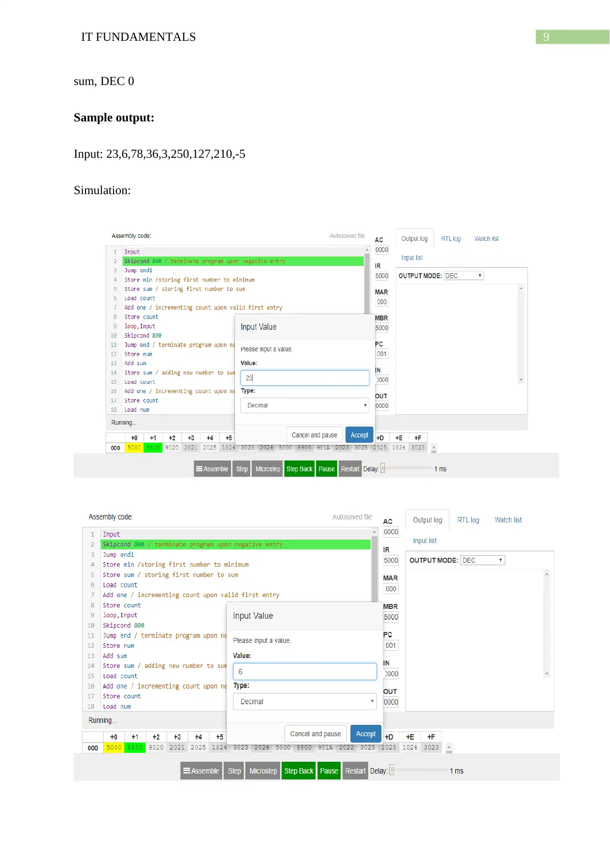
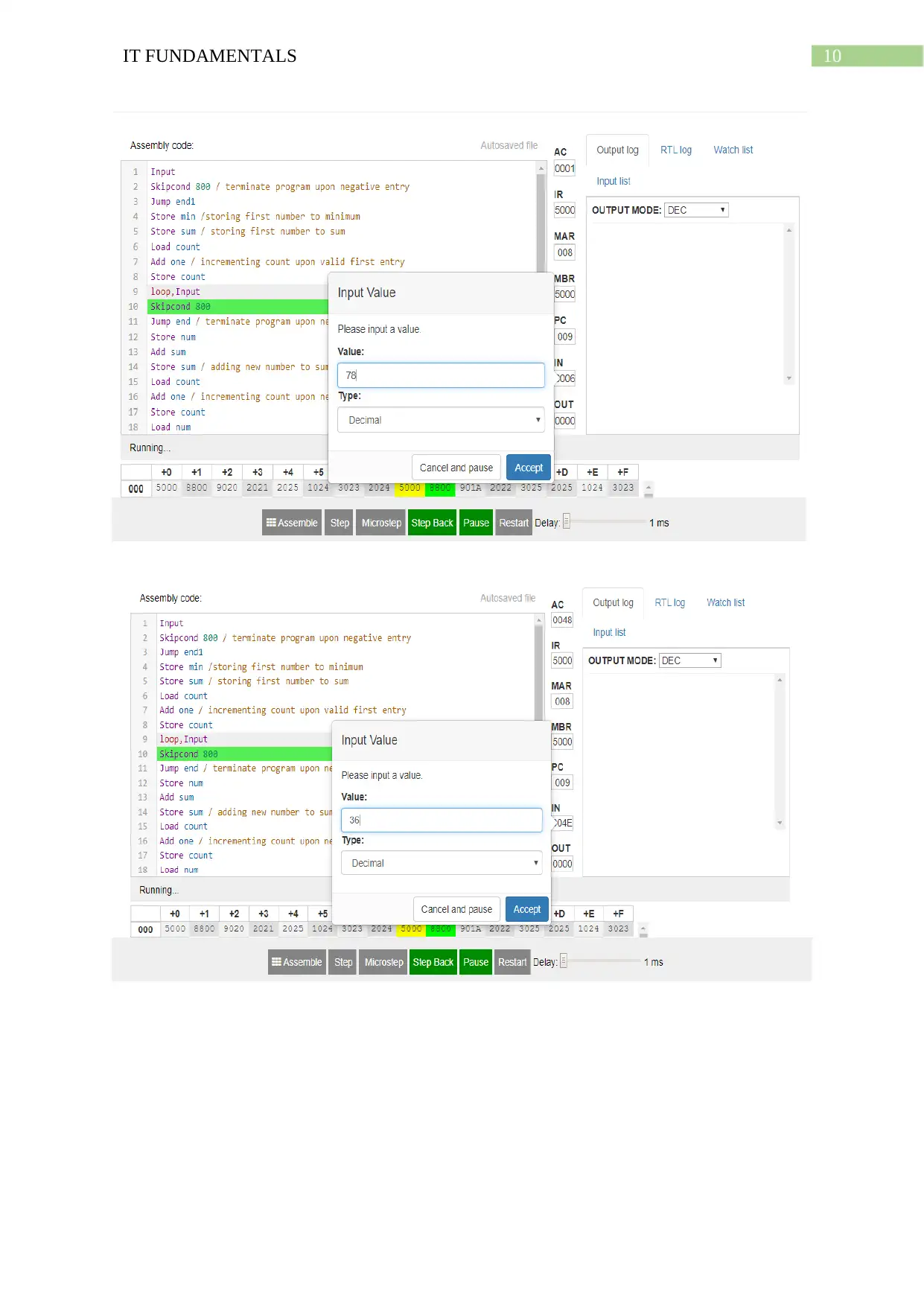
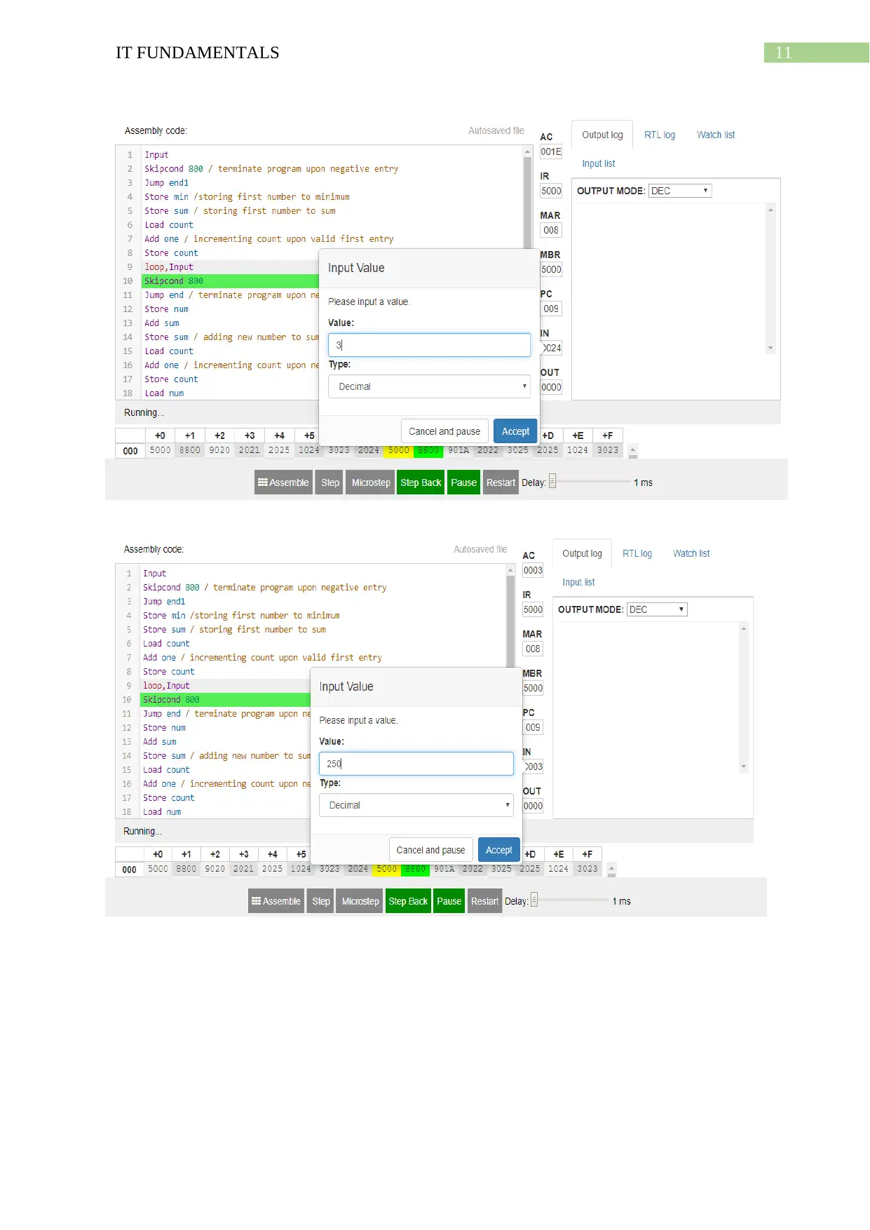
Sample output:
Input: 23,6,78,36,3,250,127,210,-5
Simulation:
sum, DEC 0
Sample output:
Input: 23,6,78,36,3,250,127,210,-5
Simulation:
Paraphrase This Document
Need a fresh take? Get an instant paraphrase of this document with our AI Paraphraser
10IT FUNDAMENTALS
11IT FUNDAMENTALS
⊘ This is a preview!⊘
Do you want full access?
Subscribe today to unlock all pages.

Trusted by 1+ million students worldwide
1 out of 15
Related Documents
Your All-in-One AI-Powered Toolkit for Academic Success.
+13062052269
info@desklib.com
Available 24*7 on WhatsApp / Email
![[object Object]](/_next/static/media/star-bottom.7253800d.svg)
Unlock your academic potential
Copyright © 2020–2026 A2Z Services. All Rights Reserved. Developed and managed by ZUCOL.


