SBM4104 IT Infrastructure Proposal: Network Design for ITech Company
VerifiedAdded on 2023/06/12
|21
|3407
|275
Report
AI Summary
This report presents an IT infrastructure proposal for ITech Company, focusing on a new network design to replace the existing inefficient flat network. The proposal outlines objectives such as future scalability, easy network management, and enhanced security. It details IT infrastructure components, a 3-layer hierarchical network model, dedicated server design, and cloud-based design options (Microsoft and Navisite). The report includes a simulation of the data center using the proposed network design, covering DHCP configuration, DNS and web-server setup, and web-server access. The proposed future network design emphasizes differentiated blocks performing specific tasks, based on a three-layered hierarchical architecture for flexibility, scalability, and ease of management. The report also addresses the geographical scope of ITech's network, spanning multiple buildings, and recommends the use of Class B IP addresses for scalability and flexibility. It concludes with recommendations for ITech to enhance its network infrastructure.
It
it infrastructure
Proposal Report for Network Design in ITech Company
APRIL 27, 2018
Student name
Course Name and ID
it infrastructure
Proposal Report for Network Design in ITech Company
APRIL 27, 2018
Student name
Course Name and ID
Paraphrase This Document
Need a fresh take? Get an instant paraphrase of this document with our AI Paraphraser
Table of Contents
1.0 Introduction.........................................................................................................................................2
1.0.1 Objectives of the Proposal.....................................................................................................3
2.0 Background Info..................................................................................................................................3
3.0 Components of IT Infrastructure.......................................................................................................4
3.0.1 ITech hardware components.......................................................................................................4
3.0.2 Software Components..................................................................................................................5
4.0 3-layer Hierarchical Model...................................................................................................................5
4.0.1 Current IT Infrastructure of ITech analysis....................................................................................1
4.0.2 Future IT Infrastructure in ITech................................................................................................1
4.1 Geographical Diagram of the network design......................................................................................2
4.1.1 Access layer....................................................................................................................................2
4.1.2 Distribution Layer..........................................................................................................................3
4.1.3 Core Layer......................................................................................................................................3
4.2 Scalability..........................................................................................................................................4
4.3 Dedicated Server Design...................................................................................................................4
4.4 Logical design of Network.................................................................................................................5
4.4 Network Mask and IP Addresses......................................................................................................6
5.0 Cloud-Based Design.............................................................................................................................6
5.0.1 Microsoft.......................................................................................................................................6
5.0.2 Navisite..........................................................................................................................................7
6.0 Network Simulation..............................................................................................................................8
6.0.1 DHCP Configuration....................................................................................................................9
6.0.2 ITech DNS and ITech Web-Servers Configuration.................................................................10
6.0.4 ITech Web-Server Access using other machines (“www.ITech.org.au”)................................14
7.0 Recommendations..............................................................................................................................14
8.0 Conclusions........................................................................................................................................14
References Lists.......................................................................................................................................15
Table of Figures
Figure 1 3-layered hierarchical model.............................................................................................5
Figure 2 Current IT Infrastructure of ITech analysis.......................................................................1
Figure 3 Current IT Infrastructure of ITech company Analysis......................................................2
Figure 4 Access layer diagram........................................................................................................3
Figure 5 Core layer diagram............................................................................................................4
Figure 6 Logical Diagram................................................................................................................5
Figure 7 IP addressing table............................................................................................................6
Figure 8 MS Azure..........................................................................................................................7
Figure 9 Network simulation...........................................................................................................8
Figure 10 Configurations using DHCP............................................................................................9
Figure 11 DHCP configurations to devices...................................................................................10
Figure 12 dhcp configuring the DNS.............................................................................................11
Figure 13 DHCP configuring the Web server...............................................................................11
Figure 14 creating a webpage in a webserver................................................................................12
Figure 15listing the available networks.........................................................................................13
Figure 16 Completing the DNS configuration by turning it ON...................................................13
Figure 17Web server access..........................................................................................................14
⊘ This is a preview!⊘
Do you want full access?
Subscribe today to unlock all pages.
Trusted by 1+ million students worldwide
1.0 Introduction
Networking is defined as the process of interconnecting set of computing devices that are used
for the purpose of communicating and much more sharing of information and resources on the
same platform (Brandley, 2017).during the network implementations many organizations may
opt to use different designs in designing their office or firm network. This report is proposal that
is implemented on the basis that the ITech is wishing to replace the network in existence with an
advanced and improved on that will satisfy all the needs of the company in terms of the
performance (Long, 2010).
1.0.1 Objectives of the Proposal
The main objectives of this proposal are highlighted as indicated here below.
The main idea for ITech is considerations of future scalability of the network (Coleman,
2012).This network design to be created have to accommodate the need of additional of
equipment’s if need be arises in future in where we will have to do redesign the network
again from scratch.
The other objective is how it will be easy in managing the network. The idea behind this
is that the design should be developed in a way that it will be easy to troubleshoot in
situations where problems are experienced.
Last but not least is the network enhancing an environment that is more secure for the
operations of ITech on the way it renders it services to its customers and the adjacent
between the offices in the given buildings.
The idea behind this proposal is doing an analysis that is through the use of IT infrastructure
components, the need of why ITech is designing the network, the 3-layerered hierarchical
network design, dedicated server, Cloud-based design, and the simulation of the data center
using the proposed network design for ITech.
2.0 Background Info
ITech is a company that deals with computer hardware’s and software’s and have offices in
different buildings that are adjacent to each other and need to use the same network in
communicating and sharing information and resources. The company have more than 2000
workstations in all the buildings. The company also have a data center that help in data
Paraphrase This Document
Need a fresh take? Get an instant paraphrase of this document with our AI Paraphraser
monitoring in all the buildings. At the data center the company has mail servers, the web-servers,
domain name servers (DNS) and others. The domain name for ITech organization will be
“www.ITech.org.au”. The need for designing a new network in ITech is because the existing
network design is poorly and not efficient in terms of performance.
3.0 Components of IT Infrastructure
In the infrastructure of IT there are a lot of equipment’s that are used in facilitating the good
design of a network in many organisations in different ways. The following Components will be
used designing the Network of ITech Company.
3.0.1 ITech hardware components
Some of the networking hardware devices to be used by ITech are as described in the table
below.
Devices Functionality
1 cable This are the media transmissions that are used for connecting the devices in
networking over the network. In this case the Ethernet cable will be used in
connecting the backbones of the network and the ITech layers of the
designed network.
2 Router This is the device used in connecting the ITech local area networks from the
different adjacent buildings. Router provides the access to external
connections such as where we use the internet in situations of cloud-based
approach.
3 Switch For achievement of the scalability and the objectives, the switch will
enhance how flexible and scalable the network will be during configuration.
4 Servers The servers are used for enhancing the storage and sharing of the network
resources in ITech Company.
5 WAP
device
The wireless Access Point devices are used for broadcasting the WI-FI
signals across the ITech company where many users can access the network
using wireless connections.
6 Access These are the communicating devices that uses the network for
Devices communications and they may include things like Desktops (PCs), mobile
phones, IP phones and other many devices
3.0.2 Software Components
In software the platforms behind this components are such as the Operating systems (OS) this
may be like the NOS which is used by servers for management and accessibility of resources. In
this scenario of ITech the network design entirely will depend much on the described
components of IT Infrastructure for any organization to be successful on any design of the
network. For the hardware each and every component may have system software that manages it
and which helps in determination of the entire ITech network performance.
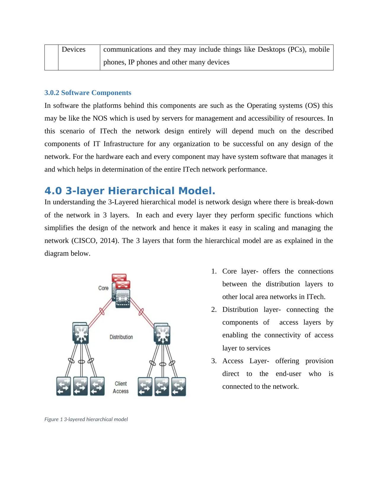
4.0 3-layer Hierarchical Model.
In understanding the 3-Layered hierarchical model is network design where there is break-down
of the network in 3 layers. In each and every layer they perform specific functions which
simplifies the design of the network and hence it makes it easy in scaling and managing the
network (CISCO, 2014). The 3 layers that form the hierarchical model are as explained in the
diagram below.
Figure 1 3-layered hierarchical model
1. Core layer- offers the connections
between the distribution layers to
other local area networks in ITech.
2. Distribution layer- connecting the
components of access layers by
enabling the connectivity of access
layer to services
3. Access Layer- offering provision
direct to the end-user who is
connected to the network.
phones, IP phones and other many devices
3.0.2 Software Components
In software the platforms behind this components are such as the Operating systems (OS) this
may be like the NOS which is used by servers for management and accessibility of resources. In
this scenario of ITech the network design entirely will depend much on the described
components of IT Infrastructure for any organization to be successful on any design of the
network. For the hardware each and every component may have system software that manages it
and which helps in determination of the entire ITech network performance.
4.0 3-layer Hierarchical Model.
In understanding the 3-Layered hierarchical model is network design where there is break-down
of the network in 3 layers. In each and every layer they perform specific functions which
simplifies the design of the network and hence it makes it easy in scaling and managing the
network (CISCO, 2014). The 3 layers that form the hierarchical model are as explained in the
diagram below.
Figure 1 3-layered hierarchical model
1. Core layer- offers the connections
between the distribution layers to
other local area networks in ITech.
2. Distribution layer- connecting the
components of access layers by
enabling the connectivity of access
layer to services
3. Access Layer- offering provision
direct to the end-user who is
connected to the network.
⊘ This is a preview!⊘
Do you want full access?
Subscribe today to unlock all pages.
Trusted by 1+ million students worldwide
The proposed network design for ITech Company should consider using this network design
model. The isolation of the network layers make it easy for Itech in managing the entire network
as well as enhancing the extensibility in future.
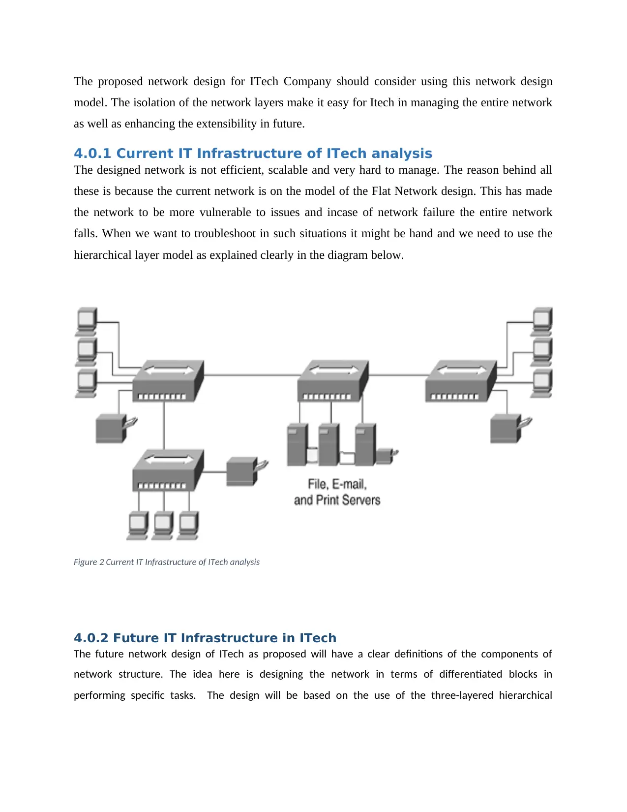
4.0.1 Current IT Infrastructure of ITech analysis
The designed network is not efficient, scalable and very hard to manage. The reason behind all
these is because the current network is on the model of the Flat Network design. This has made
the network to be more vulnerable to issues and incase of network failure the entire network
falls. When we want to troubleshoot in such situations it might be hand and we need to use the
hierarchical layer model as explained clearly in the diagram below.
Figure 2 Current IT Infrastructure of ITech analysis
4.0.2 Future IT Infrastructure in ITech
The future network design of ITech as proposed will have a clear definitions of the components of
network structure. The idea here is designing the network in terms of differentiated blocks in
performing specific tasks. The design will be based on the use of the three-layered hierarchical
model. The isolation of the network layers make it easy for Itech in managing the entire network
as well as enhancing the extensibility in future.
4.0.1 Current IT Infrastructure of ITech analysis
The designed network is not efficient, scalable and very hard to manage. The reason behind all
these is because the current network is on the model of the Flat Network design. This has made
the network to be more vulnerable to issues and incase of network failure the entire network
falls. When we want to troubleshoot in such situations it might be hand and we need to use the
hierarchical layer model as explained clearly in the diagram below.
Figure 2 Current IT Infrastructure of ITech analysis
4.0.2 Future IT Infrastructure in ITech
The future network design of ITech as proposed will have a clear definitions of the components of
network structure. The idea here is designing the network in terms of differentiated blocks in
performing specific tasks. The design will be based on the use of the three-layered hierarchical
Paraphrase This Document
Need a fresh take? Get an instant paraphrase of this document with our AI Paraphraser
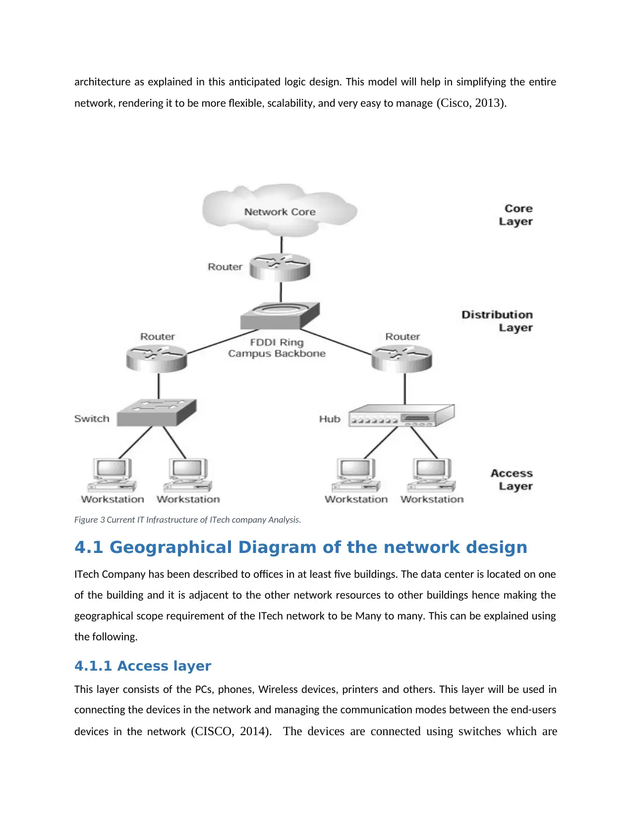
architecture as explained in this anticipated logic design. This model will help in simplifying the entire
network, rendering it to be more flexible, scalability, and very easy to manage (Cisco, 2013).
Figure 3 Current IT Infrastructure of ITech company Analysis.
4.1 Geographical Diagram of the network design
ITech Company has been described to offices in at least five buildings. The data center is located on one
of the building and it is adjacent to the other network resources to other buildings hence making the
geographical scope requirement of the ITech network to be Many to many. This can be explained using
the following.
4.1.1 Access layer
This layer consists of the PCs, phones, Wireless devices, printers and others. This layer will be used in
connecting the devices in the network and managing the communication modes between the end-users
devices in the network (CISCO, 2014). The devices are connected using switches which are
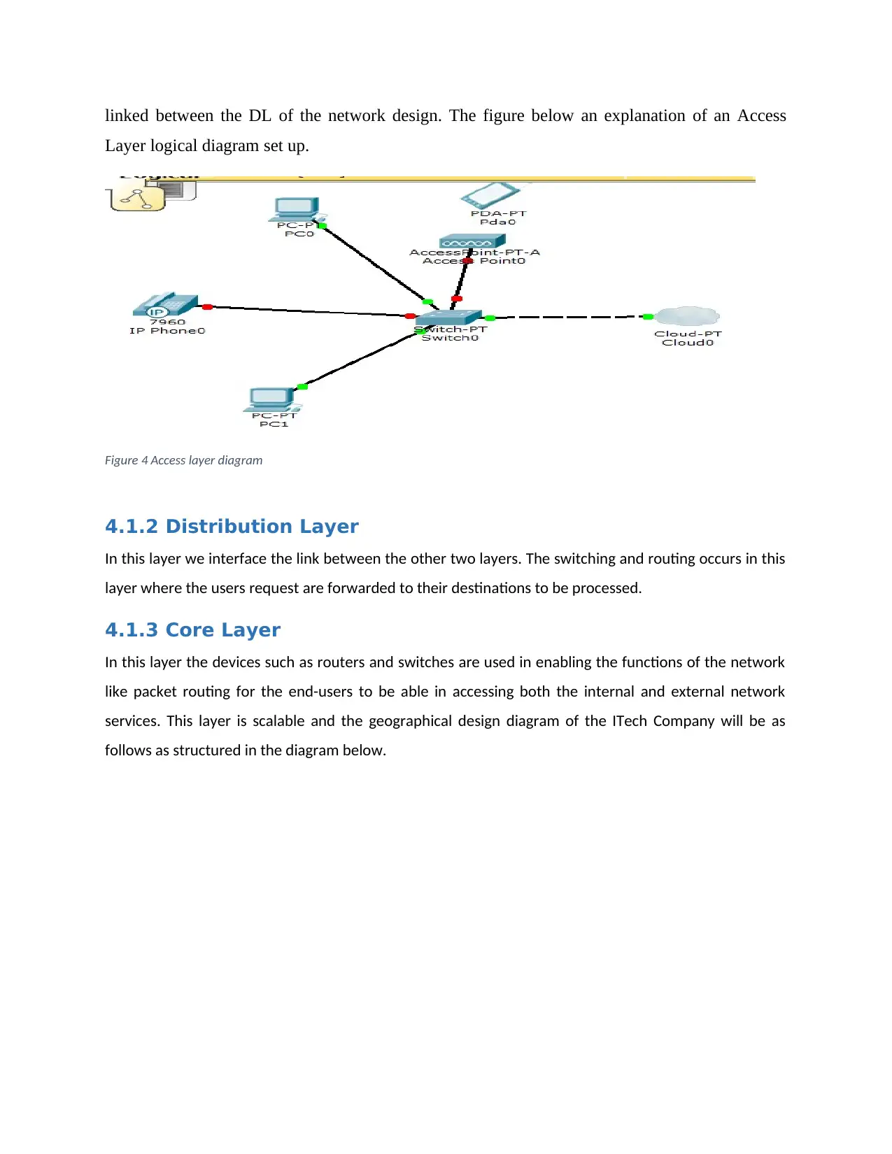
linked between the DL of the network design. The figure below an explanation of an Access
Layer logical diagram set up.
Figure 4 Access layer diagram
4.1.2 Distribution Layer
In this layer we interface the link between the other two layers. The switching and routing occurs in this
layer where the users request are forwarded to their destinations to be processed.
4.1.3 Core Layer
In this layer the devices such as routers and switches are used in enabling the functions of the network
like packet routing for the end-users to be able in accessing both the internal and external network
services. This layer is scalable and the geographical design diagram of the ITech Company will be as
follows as structured in the diagram below.
⊘ This is a preview!⊘
Do you want full access?
Subscribe today to unlock all pages.
Trusted by 1+ million students worldwide
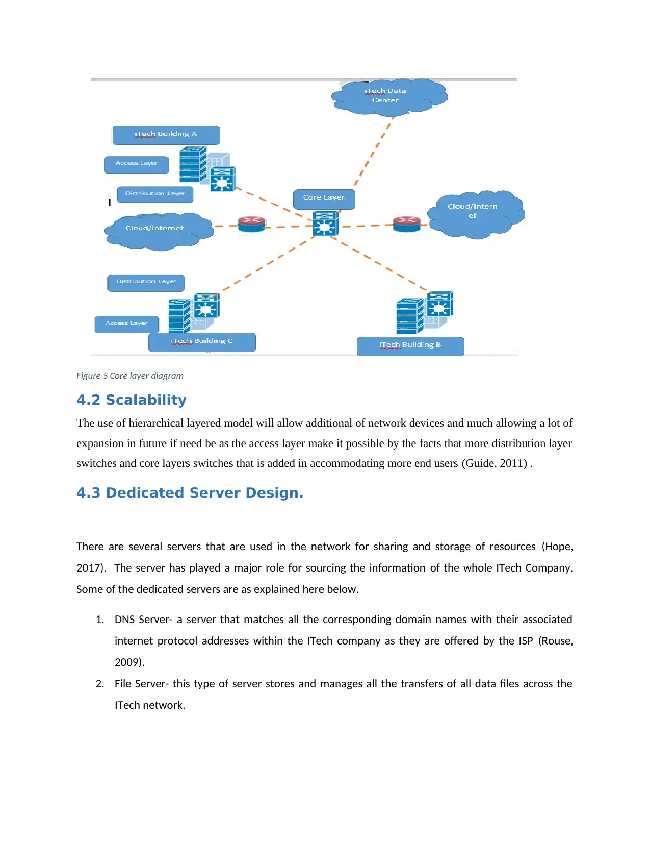
Figure 5 Core layer diagram
4.2 Scalability
The use of hierarchical layered model will allow additional of network devices and much allowing a lot of
expansion in future if need be as the access layer make it possible by the facts that more distribution layer
switches and core layers switches that is added in accommodating more end users (Guide, 2011) .
4.3 Dedicated Server Design.
There are several servers that are used in the network for sharing and storage of resources (Hope,
2017). The server has played a major role for sourcing the information of the whole ITech Company.
Some of the dedicated servers are as explained here below.
1. DNS Server- a server that matches all the corresponding domain names with their associated
internet protocol addresses within the ITech company as they are offered by the ISP (Rouse,
2009).
2. File Server- this type of server stores and manages all the transfers of all data files across the
ITech network.
Paraphrase This Document
Need a fresh take? Get an instant paraphrase of this document with our AI Paraphraser
3. Web server- this server uses HTTP for providing responses to the users when any query for web-
page that is hosted in the server. In this case of ITech the web server domain is
“www.ITech.org.au” (Margaret, 2017).
4. DHCP server – this is used for assigning the end-users and all other devices on the networks
their respective addresses.
5. Mail server- this used for managing all email of users in the transfer that is across the network.
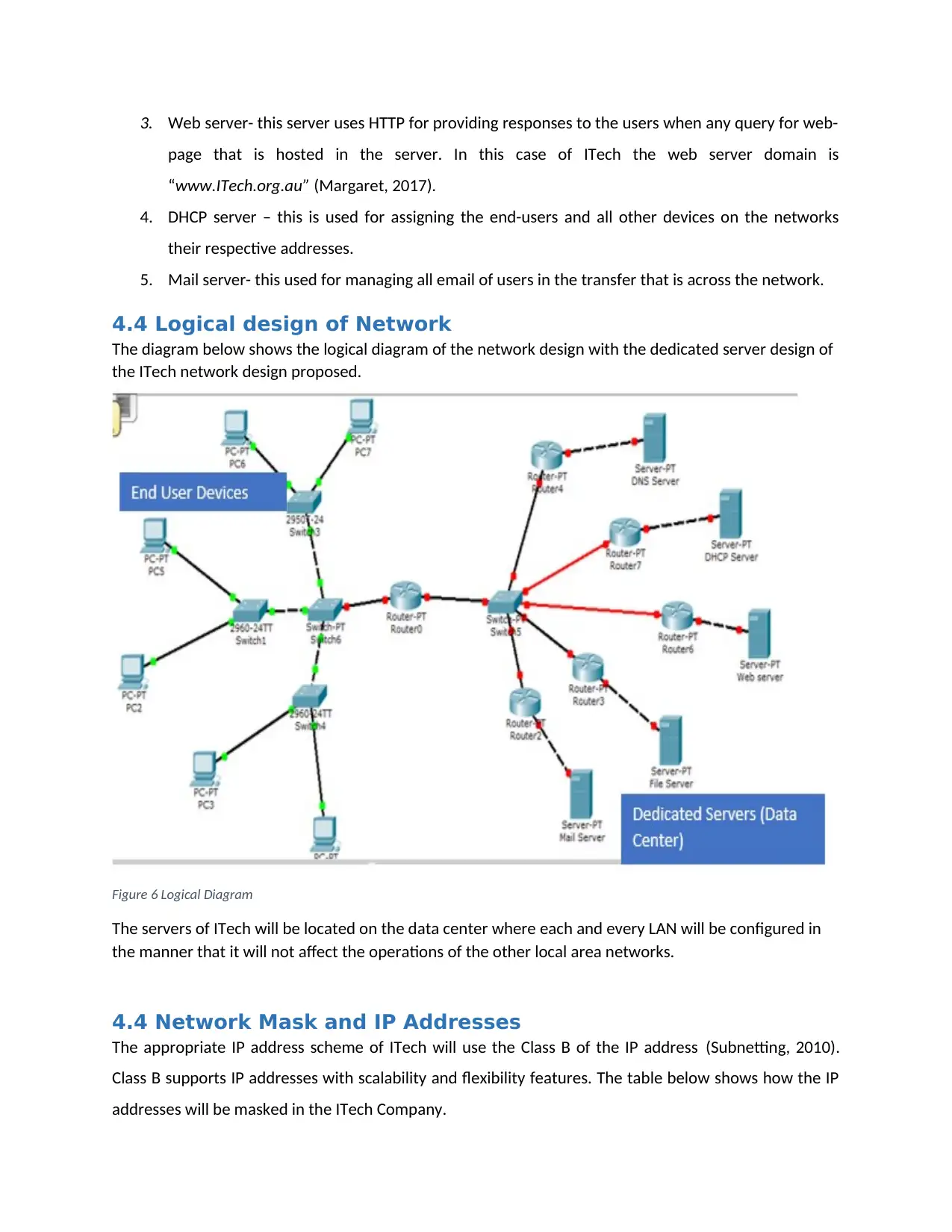
4.4 Logical design of Network
The diagram below shows the logical diagram of the network design with the dedicated server design of
the ITech network design proposed.
Figure 6 Logical Diagram
The servers of ITech will be located on the data center where each and every LAN will be configured in
the manner that it will not affect the operations of the other local area networks.
4.4 Network Mask and IP Addresses
The appropriate IP address scheme of ITech will use the Class B of the IP address (Subnetting, 2010).
Class B supports IP addresses with scalability and flexibility features. The table below shows how the IP
addresses will be masked in the ITech Company.
page that is hosted in the server. In this case of ITech the web server domain is
“www.ITech.org.au” (Margaret, 2017).
4. DHCP server – this is used for assigning the end-users and all other devices on the networks
their respective addresses.
5. Mail server- this used for managing all email of users in the transfer that is across the network.
4.4 Logical design of Network
The diagram below shows the logical diagram of the network design with the dedicated server design of
the ITech network design proposed.
Figure 6 Logical Diagram
The servers of ITech will be located on the data center where each and every LAN will be configured in
the manner that it will not affect the operations of the other local area networks.
4.4 Network Mask and IP Addresses
The appropriate IP address scheme of ITech will use the Class B of the IP address (Subnetting, 2010).
Class B supports IP addresses with scalability and flexibility features. The table below shows how the IP
addresses will be masked in the ITech Company.
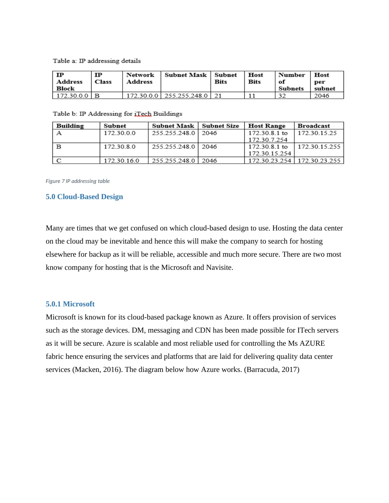
Figure 7 IP addressing table
5.0 Cloud-Based Design
Many are times that we get confused on which cloud-based design to use. Hosting the data center
on the cloud may be inevitable and hence this will make the company to search for hosting
elsewhere for backup as it will be reliable, accessible and much more secure. There are two most
know company for hosting that is the Microsoft and Navisite.
5.0.1 Microsoft
Microsoft is known for its cloud-based package known as Azure. It offers provision of services
such as the storage devices. DM, messaging and CDN has been made possible for ITech servers
as it will be secure. Azure is scalable and most reliable used for controlling the Ms AZURE
fabric hence ensuring the services and platforms that are laid for delivering quality data center
services (Macken, 2016). The diagram below how Azure works. (Barracuda, 2017)
⊘ This is a preview!⊘
Do you want full access?
Subscribe today to unlock all pages.
Trusted by 1+ million students worldwide
1 out of 21
Related Documents


Your All-in-One AI-Powered Toolkit for Academic Success.
+13062052269
info@desklib.com
Available 24*7 on WhatsApp / Email
![[object Object]](/_next/static/media/star-bottom.7253800d.svg)
Unlock your academic potential
Copyright © 2020–2026 A2Z Services. All Rights Reserved. Developed and managed by ZUCOL.