IT Networking Design Project: WAN for Sydney & Singapore Offices
VerifiedAdded on 2020/04/01
|12
|2150
|36
Project
AI Summary
This project details the design of a Wide Area Network (WAN) connecting two offices, one in Sydney and another in Singapore. The assignment begins with an executive summary and table of contents, followed by an introduction outlining the project's scope and goals: to establish a secure and efficient network. Design requirements are discussed, considering business constraints, technical goals, user communities, and necessary assumptions. The logical network design includes diagrams, addressing, and explanations of routing and switching protocols, along with security mechanisms like firewalls. The physical network design provides a final network diagram, device details, software, and cost estimations. A test plan is presented to evaluate the network's performance, including volume, stress, recovery, security, and performance testing. The project concludes with a detailed test script for security testing and a comprehensive list of references.

it networking Design
Paraphrase This Document
Need a fresh take? Get an instant paraphrase of this document with our AI Paraphraser
Executive summary
A network diagram that reflects the Wide Area network between the two companies one at
Sydney and other at Singapore is designed. The network diagram is designed by keeping in mind
the business constraints and the safe network requirements. The logical and physical network
diagrams are explained clearly.
1
Table of Contents
1. Introduction.......................................................................................................................................3
2. Project Goal.......................................................................................................................................3
3. Project Scope......................................................................................................................................3
4. Design requirements.........................................................................................................................3
5. Logical Network Design...................................................................................................................5
6. Physical Network Design...................................................................................................................6
7. Conclusion..........................................................................................................................................8
References..................................................................................................................................................9
2
⊘ This is a preview!⊘
Do you want full access?
Subscribe today to unlock all pages.
Trusted by 1+ million students worldwide
1. Introduction
The network design following the criteria mentioned will be carried out. The
requirements will be formulated to meet the features of a safe network. Proper connections and
justification for using different devices and their purpose will be mentioned. The network will be
designed by keeping the user communities in mind.
2. Project Goal
To design a WAN for two offices with business constraints and security features.
3. Project Scope
Sydney office and Singapore office should be provided with a desirable Network setup
establishing proper communication and connection between the client and the servers.
4. Design requirements
a) Business Goals and Constraints
In implementation process the requirements are the major part. The design of this project
is to develop and run the network for both the offices located in Singapore and Sydney. This is
the main requirement of this project. The requirements should meet the designing of the system
and running functional architecture. (Ecomputernotes.com, 2017).
b) Technical Goals and Tradeoffs
To identify the requirements of all the network. To generate IP address for internal
communication. The design process should meet all the hardware requirements. To protect the
system and files the security should be able to provide for every level. LAN network is
connected to the all systems. The proper channel should be used for communication and security
purposes, if there is any miscommunication will be happened. The whole area of the building
should be covered by the network. To reduce the cost for as much as possible in the organization.
(Kushki, Plataniotis and Venetsanopoulos, 2012).
3
Paraphrase This Document
Need a fresh take? Get an instant paraphrase of this document with our AI Paraphraser
c) User Communities and Network Applications
The user communities who use the network includes engineers, online customers, Data
center admins, Internal email users ,Network Administrators and Other employees. Network
applications are nothing but an architecture which uses client-server based communications.
Server asks like a master and it provides service to the client. Client can be a computer, laptop or
any device used by the end-user. A server to handle the Sydney office and another server to
handle the Singapore office is essential. In addition to this the number of servers can be
increased according to the requirement or the number of clients connected. (Mankell and
Segerberg, 2012)
d) List of Assumptions
The following requirements are the other requirements that must be used for design
process. The voice requirements are automatic call distribution. Virtual networking, voice
conferencing, Interactive voice responses, voicemail, computer telephony integration. The design
requirements for the infrastructure of LAN is described below. protocols for networking ,policy
enabled networks, cabling media, switches, hubs, routers, multimedia, the tools must be needed
for managing the networks like simulation, bandwidth are needed for designing the network. The
wide area network structure requires the following technologies. For example transport
technology like frame relay, ATM. and the other requirements are multimedia and multiplexing.
The following assumptions are taken for designing the network. To implementing the project all
funds are made available. To making the cost as low for implementation. The priorities will not
cause any delay for implementation changes in delivering the project deliverables. After getting
the proper permissions from the authorities, tower of antenna is installed if it is necessary. Based
on the work plan preparation, all the users must agree for that to implementing the process. The
bandwidth of the proposed system uses1mbps for the network. (Lutz, 2012).
4
5. Logical Network Design
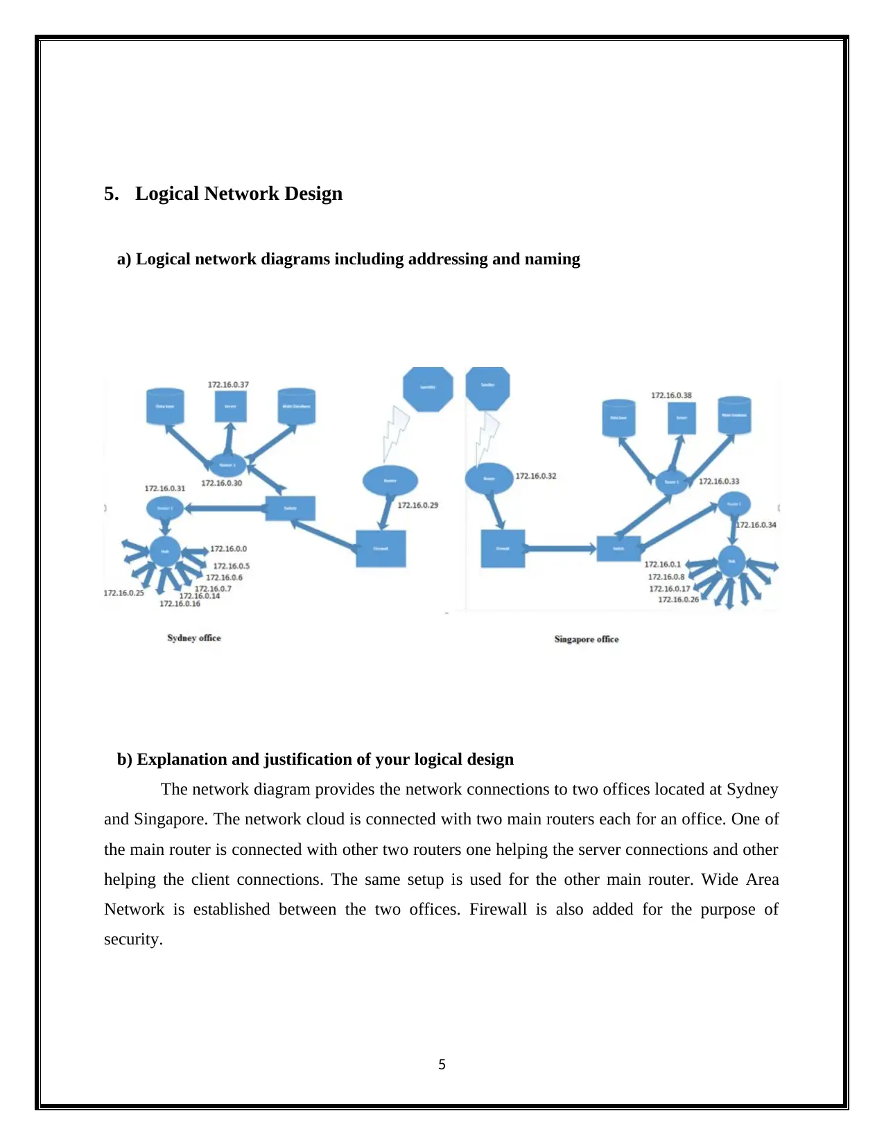
a) Logical network diagrams including addressing and naming
b) Explanation and justification of your logical design
The network diagram provides the network connections to two offices located at Sydney
and Singapore. The network cloud is connected with two main routers each for an office. One of
the main router is connected with other two routers one helping the server connections and other
helping the client connections. The same setup is used for the other main router. Wide Area
Network is established between the two offices. Firewall is also added for the purpose of
security.
5
⊘ This is a preview!⊘
Do you want full access?
Subscribe today to unlock all pages.
Trusted by 1+ million students worldwide

c) List of routing and switching protocols, and security mechanisms.
WAN
WAN is the abbreviation of Wide Area Network. It exists over a large scale area. Two or
more LANs can be connected with the help of WAN. The protocol used by WAN to establish
communication with the devices like routers, switches, modems and firewalls is TCP/IP
protocol.
LAN
LAN is the abbreviation of Local Area Network. A LAN network is spread over small
area. LAN is used for the interconnection of devices over a smaller area. LAN can interconnect
devices such as scanners, storage devices and printers.
Routers
A hardware device which assist to receive, analyze and move a packet from one network
to another network is called the router. Router has difference in performance with switches and
hubs. Router has the capability to analyze the data where switches and hubs can be only used to
implement transfers.
Firewalls
6
Paraphrase This Document
Need a fresh take? Get an instant paraphrase of this document with our AI Paraphraser
Firewalls is a security device for external network devices. It provide the service for
Web, e-mail DNS and FTP. It operates based Tcp, source IP address, destination IP address,
source port number, destination port number. It is used to control the traffic diminished.
Switch:
It is used to connect computer into other devices. It handles only the packets of data. It
saves the bandwidth. It is more efficient. With the help of switch, one cloud allow or disallow the
connection for the circuit.
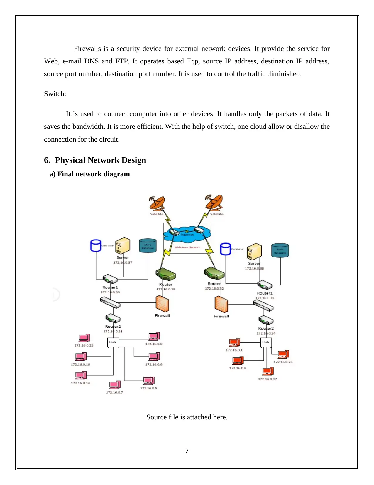
6. Physical Network Design
a) Final network diagram
Source file is attached here.
7
Web, e-mail DNS and FTP. It operates based Tcp, source IP address, destination IP address,
source port number, destination port number. It is used to control the traffic diminished.
Switch:
It is used to connect computer into other devices. It handles only the packets of data. It
saves the bandwidth. It is more efficient. With the help of switch, one cloud allow or disallow the
connection for the circuit.
6. Physical Network Design
a) Final network diagram
Source file is attached here.
7
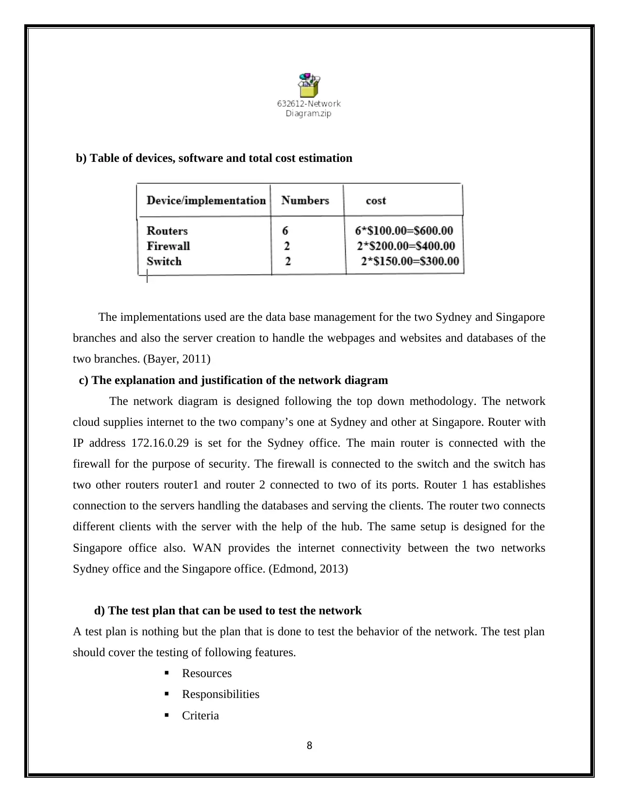
b) Table of devices, software and total cost estimation
The implementations used are the data base management for the two Sydney and Singapore
branches and also the server creation to handle the webpages and websites and databases of the
two branches. (Bayer, 2011)
c) The explanation and justification of the network diagram
The network diagram is designed following the top down methodology. The network
cloud supplies internet to the two company’s one at Sydney and other at Singapore. Router with
IP address 172.16.0.29 is set for the Sydney office. The main router is connected with the
firewall for the purpose of security. The firewall is connected to the switch and the switch has
two other routers router1 and router 2 connected to two of its ports. Router 1 has establishes
connection to the servers handling the databases and serving the clients. The router two connects
different clients with the server with the help of the hub. The same setup is designed for the
Singapore office also. WAN provides the internet connectivity between the two networks
Sydney office and the Singapore office. (Edmond, 2013)
d) The test plan that can be used to test the network
A test plan is nothing but the plan that is done to test the behavior of the network. The test plan
should cover the testing of following features.
Resources
Responsibilities
Criteria
8
⊘ This is a preview!⊘
Do you want full access?
Subscribe today to unlock all pages.
Trusted by 1+ million students worldwide
Approach
Procedures
The types of testing that is done to test the performance of the network included the following
i. Volume testing
ii. Stress Testing
iii. Recovery testing
iv. Security testing
v. Performance testing
Volume testing
The goal of volume testing is to measure the application performance. It is done based on
the variation of database. It is one type of nonfunctional testing. It is little bit different from load
and stress testing.
Stress testing
It is used to measure the stability of the software application.it is also used to identify the
failure of the system.it is a nonfunctional testing. The load limit of the stress testing is above
threshold of break.
Load testing
It is used to check the staying power and response time. It fix the SLA for the software
application. The load limit of the load testing is up to threshold of break.
Examples of load testing:
Write and read the data continuously in the hard disk.
Send large job to test the printer.
Access many mail boxes to test the mail server.
Run many application in the server.
Security testing
It is commonly used in government work station, enterprises, schools and colleges. The
network security is needed in five levels. The five levels are network, Application, Host, data
and perimeter.
e) The detailed test script for one of the tests in the test plan
9
Paraphrase This Document
Need a fresh take? Get an instant paraphrase of this document with our AI Paraphraser
Security testing is nothing but the vulnerability scanning. Security testing can be done
with the following soft wares or the devices like file integrity checkers, log reviewers, WAN
drive testers and also by using some of the methods like penetration testing. (Goodall, 2016)
Penetration testing
In penetration testing, the testers evaluate the security features of a network based on the design
and the implementation. Penetration testing is nothing but simulating the attack tools forcefully
and test whether the network is able to resist the harm generated by the attack tools. Penetrating
testing has four stages. They are
Planning
Discovery
Attack
Reporting
7. Conclusion
The network is designed following the provided criteria. The network is designed with
safety features. Justification for the design and the network is given.
References
Bayer, W. (2011). Switch. [Hertford, NC]: Crossroad Press.
Bhowmik, S. (2017). Cloud Computing. Cambridge: Cambridge University Press.
Breeding, M. (2012). Cloud computing. London: Facet.
Buyya, R., Vecchiola, C. and Selvi, S. (2013). Mastering cloud computing. Waltham, MA:
Morgan Kaufmann.
Dooley, B. (2011). The definitive analysis of broadband wireless networks. [Place of publication
not identified]: Mind Commerce.
10
Ecomputernotes.com. (2017). Carrier Sense Multiple Access with Collision Avoidance
(CSMA/CA). [online] Available at:
http://ecomputernotes.com/computernetworkingnotes/multiple-access/carrier-sense-multiple-
access-with-collision-avoidance [Accessed 30 Sep. 2017].
Edmond, M. (2013). The switch. Auckland: Auckland University Press.
Ettefagh, A. (2011). Cooperative WLAN protocols for multimedia communication. Berlin:
Logos Verlag GmbH.
Goodall, C. (2016). Switch. [Place of publication not identified]: Profile Books.
Kushki, A., Plataniotis, K. and Venetsanopoulos, A. (2012). WLAN positioning systems.
Cambridge [u.a.]: Cambridge Univ. Press.
Lutz, J. (2012). Switch. New York: Pinnacle Books/Kensington Publishing Corp.
Mankell, H. and Segerberg, E. (2012). Firewall. London: Vintage.
Mills, D. (n.d.). Firewall.
Muller, N. (2003). WiFi for the enterprise. New York: McGraw-Hill.
Velte, A., Velte, T. and Elsenpeter, R. (2010). Cloud computing. New York: McGraw-Hill.
Wei, H., Dixit, S. and Rykowski, J. (2013). WiFi, WiMAX and LTE multi-hop mesh networks.
Hoboken, NJ: Wiley.
Yadav, A. and Upmanu, V. (2012). Beam Forming Network For WLAN. Saarbrücken: LAP
LAMBERT Academic Publishing.
Yang, X. and Shang, R. (2012). Luo yang qie lan ji. Beijing: Zhong hua shu ju.
11
⊘ This is a preview!⊘
Do you want full access?
Subscribe today to unlock all pages.
Trusted by 1+ million students worldwide
1 out of 12
Related Documents


Your All-in-One AI-Powered Toolkit for Academic Success.
+13062052269
info@desklib.com
Available 24*7 on WhatsApp / Email
![[object Object]](/_next/static/media/star-bottom.7253800d.svg)
Unlock your academic potential
Copyright © 2020–2026 A2Z Services. All Rights Reserved. Developed and managed by ZUCOL.