ITC508 Object Modelling: Car Parking System Validation Phase Report
VerifiedAdded on 2024/06/03
|22
|2458
|317
Report
AI Summary
This report focuses on the validation phase of the Collins Car Parking System, building upon previous inspection and elaboration phases. It details the entry and exit subsystems using use case and sequence diagrams, illustrating the interactions between actors and system components. The report includes descriptions of sequence diagram activities, a full use case diagram, and a class diagram representing the system's structure. The diagrams cover processes such as ticket generation, card validation, parking space allocation, and payment processing, providing a comprehensive overview of the system's validation.
ITC508
Object Modelling
Assessment Item3
Validation phase
Student Name-
Student ID-
Object Modelling
Assessment Item3
Validation phase
Student Name-
Student ID-
Paraphrase This Document
Need a fresh take? Get an instant paraphrase of this document with our AI Paraphraser
Table of Contents
List of Figures............................................................................................................................................2
List of Tables..............................................................................................................................................2
Introduction...............................................................................................................................................3
Interaction diagram...................................................................................................................................4
Collaboration diagram..............................................................................................................................4
Sequence diagram......................................................................................................................................4
Entry Subsystem and Exit Subsystem for Collins Car Parking System............................................5
Parking entrance system.......................................................................................................................6
Use case diagram...............................................................................................................................6
Sequence diagram..............................................................................................................................8
Parking management system..............................................................................................................10
Use case diagram.............................................................................................................................10
Sequence diagram............................................................................................................................11
Parking exit system..............................................................................................................................13
Use case diagram.............................................................................................................................13
Sequence diagram............................................................................................................................14
Full use case diagram..........................................................................................................................17
Class diagram..........................................................................................................................................19
Conclusion................................................................................................................................................20
References................................................................................................................................................21
1
List of Figures
Figure 1 Use case for car entrance system...................................................................................................6
Figure 2 Sequence diagram of car entrance system.....................................................................................7
Figure 3 Use case for car park management system....................................................................................9
Figure 4 Sequence diagram for car park management system...................................................................10
Figure 5 Use case diagram for car exit system...........................................................................................12
Figure 6 Sequence diagram for car exit system.........................................................................................13
Figure 7 Full use case description..............................................................................................................16
Figure 8 Class diagram..............................................................................................................................18
List of Tables
Table 1 Car entrance sequence diagram description..............................................................................7
Table 2 Car Park management sequence diagram description............................................................10
Table 3 Car exit sequence diagram description....................................................................................13
Table 4 Use case description...................................................................................................................16
2
⊘ This is a preview!⊘
Do you want full access?
Subscribe today to unlock all pages.
Trusted by 1+ million students worldwide
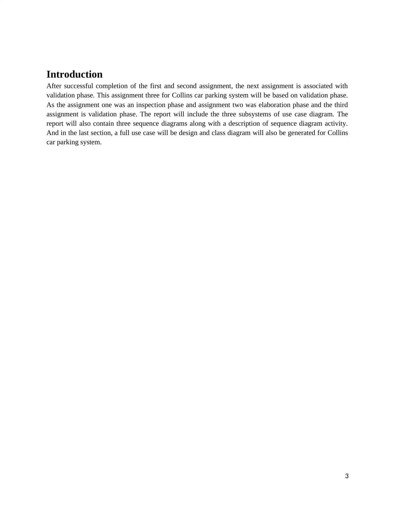
Introduction
After successful completion of the first and second assignment, the next assignment is associated with
validation phase. This assignment three for Collins car parking system will be based on validation phase.
As the assignment one was an inspection phase and assignment two was elaboration phase and the third
assignment is validation phase. The report will include the three subsystems of use case diagram. The
report will also contain three sequence diagrams along with a description of sequence diagram activity.
And in the last section, a full use case will be design and class diagram will also be generated for Collins
car parking system.
3
Paraphrase This Document
Need a fresh take? Get an instant paraphrase of this document with our AI Paraphraser
Interaction diagram
Interaction diagram is a type of model which is used to define a group of objects merged in some manner-
typically known as a single use case. The diagram depicts objects and messages which passed between
objects in use-case. There are mainly two types of the interaction diagram i.e. sequence model and
collaboration model. The diagram made is very simple and easy to understand. The only weakness of
interaction diagram is that it describes the behavior but not define the behavior. The interaction diagrams
are used to show the collaboration among the objects but not give a proper idea of the definition of
behavior (Kumar & Bhatia, 2012).
Collaboration diagram
The collaboration diagram is the type of a visual presentation which is used to show that how different
software objects interact with one another and how the clients can take advantage of this collaboration.
The collaboration diagram is made from individual software pieces. The labels used in collaboration
diagram are determined by the user base. The collaboration diagram is a combination of arcs and vertices.
For every message in a collaboration diagram, there is associated sequence number for that.
Sequence diagram
The sequence diagram is a diagram which is used to presents the object connections which is arranged in
the time order. It is used to represent classes and objects from case scenario and order of messages
interchange among objects needed to transmit out functions of scenario. The other name for sequence
diagram is event scenarios and event diagrams. In the sequence diagram, the messages are written above
on horizontal arrows which display interaction. The solid arrows head is used to represent the open
arrowheads and synchronous calls are used to represent the asynchronous messages and the dashed line is
used to represent the reply messages. If the synchronous message is sent by the caller, he must wait until
the message is done and if the message is asynchronous he can send message continuously without the
need of getting a response. The sequence diagram is a good way for visualizing and validating the
different runtime scenarios. This diagram helps to predict about a system that how it will act in certain
conditions. The Unified modeling language object symbol is used to demonstrate the class roles. The
activation box is used to represent time which an object need for completing the task. When the object is
a busy thin gray rectangle is located vertically on the lifeline. The loop in the sequence diagram is
represented by a rectangle. The reply message is represented by dotted line (Smartdraw,2017).
There are various numerous components of sequence diagram which help in envisioning a time control
flow of the system. The components use for sequence diagram are mentioned below:
a. Message- The message is the type of information which flows in between objects. The messages
are represented as a pointed line in the sequence diagram.
b. Lifeline- The lifelines are always placed on top of the sequence diagram. The lifeline is
represented by vertical dashed lines which specify object’s occurrence over time.
c. Self-message- When an object is sent to itself, it is usually shown by U shape arrow which points
back to itself.
d. Reply message- The return or reply message is drawn with the dotted line and open arrowhead
also points back to the original lifeline (Zafar,2016).
4

Entry Subsystem and Exit Subsystem for Collins Car Parking System
The Collins car parking system is designed to help the customers and to provide the parking facility.
For Collins car parking system, the subsystem used for the validation phase is entry subsystem and
exit subsystem. The subsystem deals with process start when a customer enters and ends when a
customer makes exit. In Collins car parking system user enter into premises, system manage to
provide the space for car parking for users and exits when payment is done by customers. For these
three functionalities, the three use cases are designed along with sequence diagram.
5
⊘ This is a preview!⊘
Do you want full access?
Subscribe today to unlock all pages.
Trusted by 1+ million students worldwide
Parking entrance system
There will be an access button in car parking system which will help to generate a ticket and print the
payment receipt. The barrier will open after ticket generation. A camera is also fitted to capture the
car details. The card details like car number, the color of the car, user details all get captured. At entry
point system will differentiate between the ordinary customer and fixed customer. The system has
different functionality according to customer type.
Use case diagram
The use case diagram is used to provide an overall overview of the system. There are three major
components of use case i.e. use cases, actors, and relationship. In this section, the Use case for car
entrance system will be discussed which gives an overall overview of car parking.
6
Paraphrase This Document
Need a fresh take? Get an instant paraphrase of this document with our AI Paraphraser
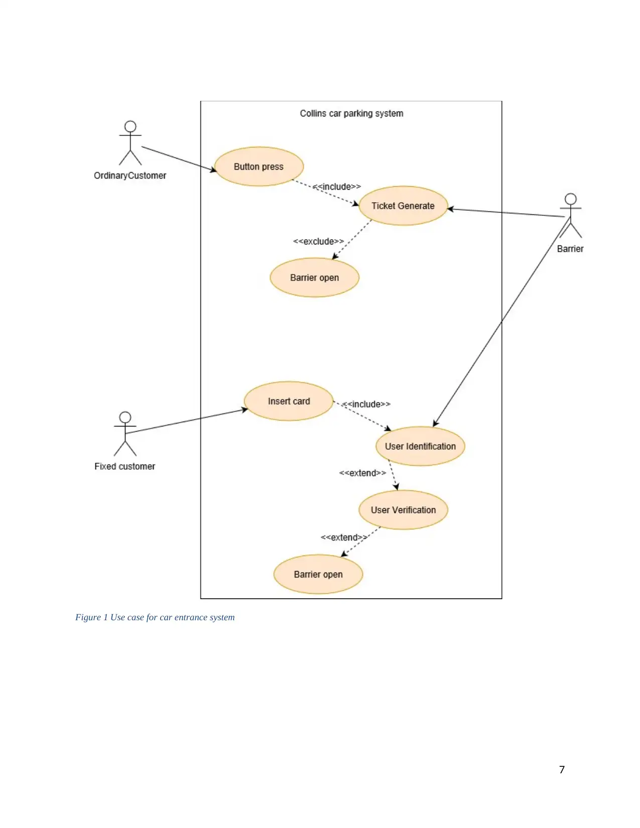
Figure 1 Use case for car entrance system
7
7
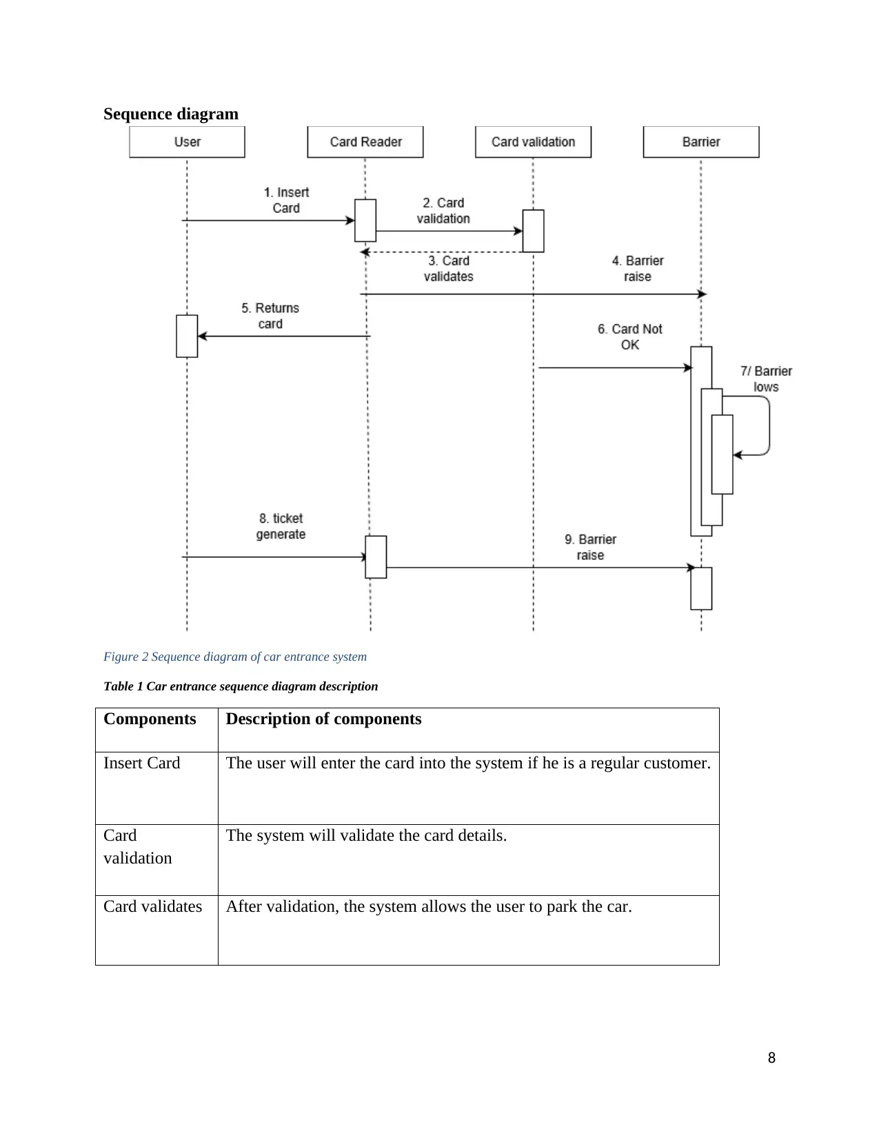
Sequence diagram
Figure 2 Sequence diagram of car entrance system
Table 1 Car entrance sequence diagram description
Components Description of components
Insert Card The user will enter the card into the system if he is a regular customer.
Card
validation
The system will validate the card details.
Card validates After validation, the system allows the user to park the car.
8
⊘ This is a preview!⊘
Do you want full access?
Subscribe today to unlock all pages.
Trusted by 1+ million students worldwide
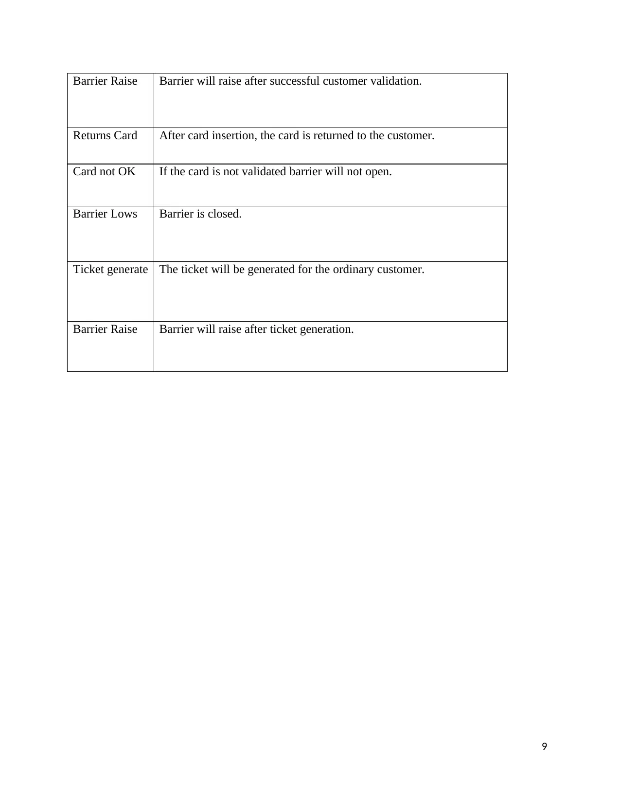
Barrier Raise Barrier will raise after successful customer validation.
Returns Card After card insertion, the card is returned to the customer.
Card not OK If the card is not validated barrier will not open.
Barrier Lows Barrier is closed.
Ticket generate The ticket will be generated for the ordinary customer.
Barrier Raise Barrier will raise after ticket generation.
9
Paraphrase This Document
Need a fresh take? Get an instant paraphrase of this document with our AI Paraphraser
Parking management system
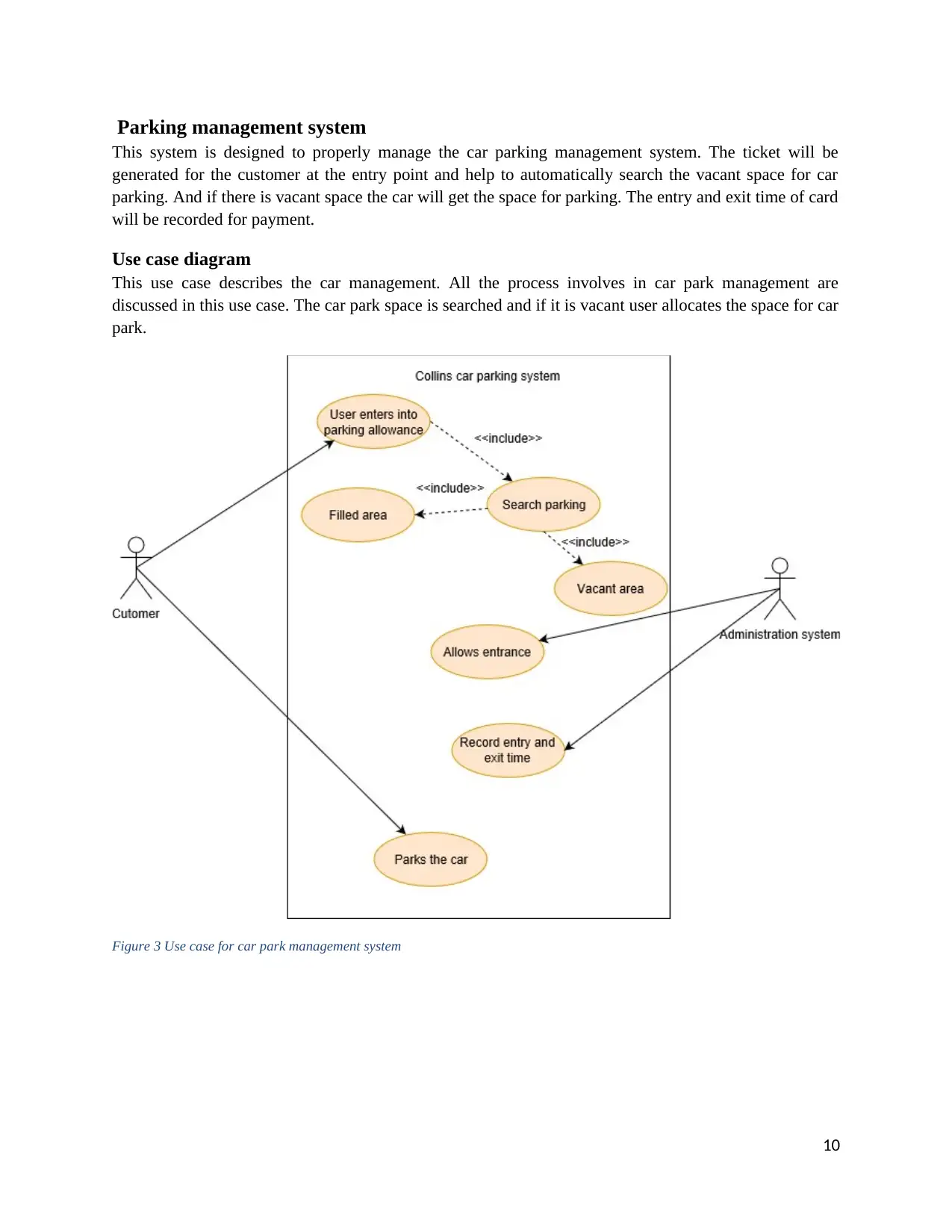
This system is designed to properly manage the car parking management system. The ticket will be
generated for the customer at the entry point and help to automatically search the vacant space for car
parking. And if there is vacant space the car will get the space for parking. The entry and exit time of card
will be recorded for payment.
Use case diagram
This use case describes the car management. All the process involves in car park management are
discussed in this use case. The car park space is searched and if it is vacant user allocates the space for car
park.
Figure 3 Use case for car park management system
10
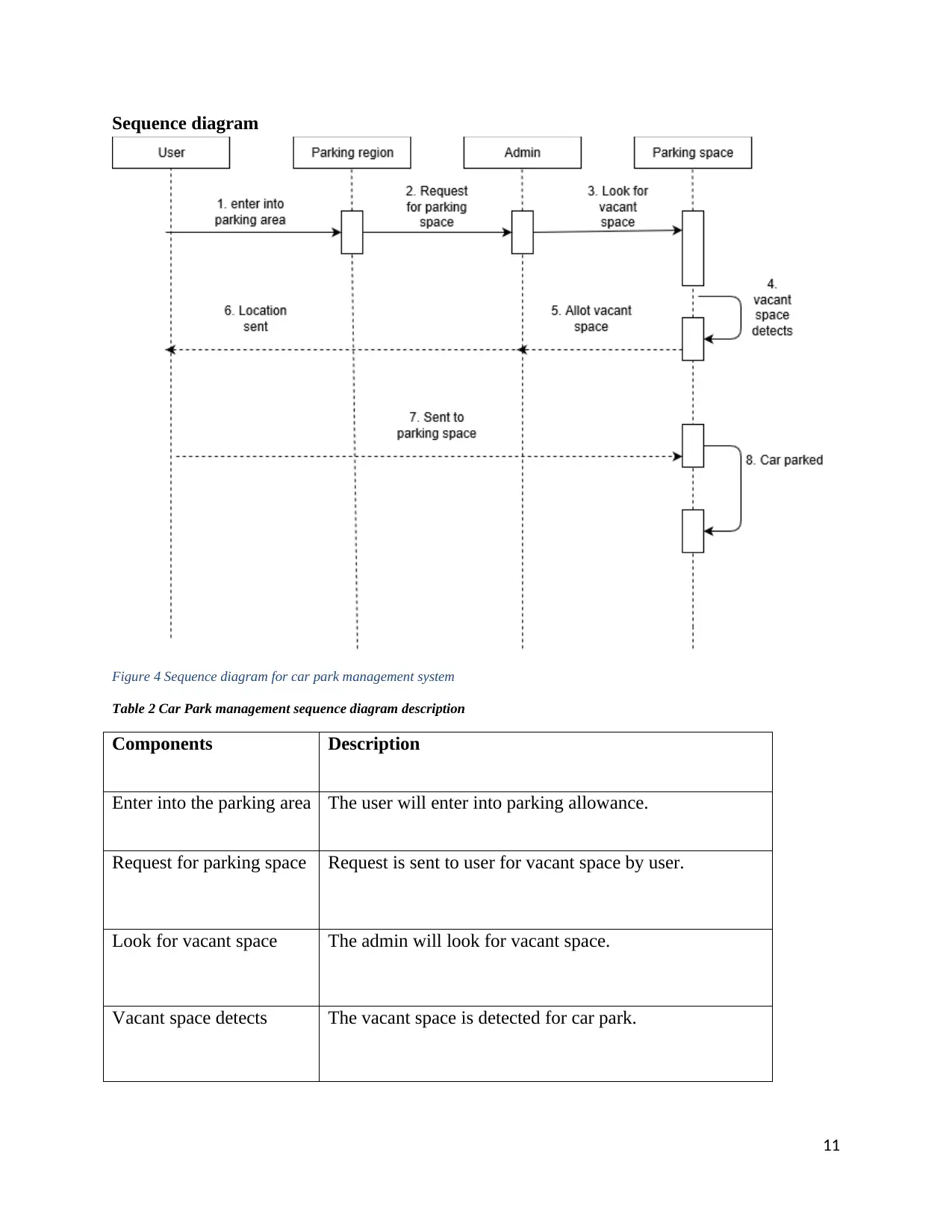
Sequence diagram
Figure 4 Sequence diagram for car park management system
Table 2 Car Park management sequence diagram description
Components Description
Enter into the parking area The user will enter into parking allowance.
Request for parking space Request is sent to user for vacant space by user.
Look for vacant space The admin will look for vacant space.
Vacant space detects The vacant space is detected for car park.
11
⊘ This is a preview!⊘
Do you want full access?
Subscribe today to unlock all pages.
Trusted by 1+ million students worldwide
1 out of 22
Related Documents


Your All-in-One AI-Powered Toolkit for Academic Success.
+13062052269
info@desklib.com
Available 24*7 on WhatsApp / Email
![[object Object]](/_next/static/media/star-bottom.7253800d.svg)
Unlock your academic potential
Copyright © 2020–2026 A2Z Services. All Rights Reserved. Developed and managed by ZUCOL.