ITC508 Object Modeling: UML Diagrams for Collin’s Car Parking System

Verified

Added on  2024/06/03

|17
|2097
|209
Project
AI Summary
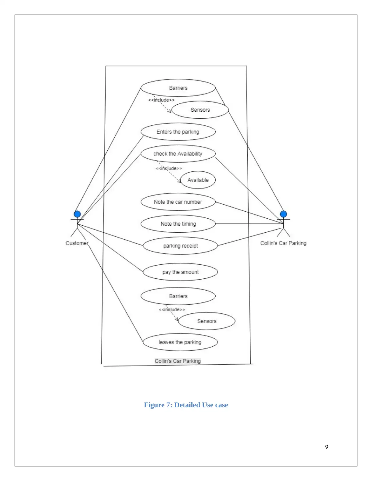
This project focuses on object modeling of Collin’s car parking system using UML diagrams. It includes the analysis of system functionalities, defining three key use cases (entering parking, payment mode, and exiting parking), and creating detailed use case diagrams. The project further develops a class diagram illustrating the classes, attributes, and operations within the system. Additionally, sequence diagrams are constructed for each of the main use cases to demonstrate the timing behavior and interactions between objects. The UML diagrams provide a comprehensive visual representation of the system's structure and behavior. Desklib provides access to similar solved assignments and resources for students.
tabler-icon-diamond-filled.svg

Contribute Materials

Your contribution can guide someone’s learning journey. Share your documents today.
Document Page
Object Modeling
ITC508
1
tabler-icon-diamond-filled.svg

Secure Best Marks with AI Grader

Need help grading? Try our AI Grader for instant feedback on your assignments.
Document Page
Contents
Introduction......................................................................................................................................3
Analysis of functionality:................................................................................................................3
Three important Use case:............................................................................................................3
Use case Diagram:.......................................................................................................................4
Class Diagram:...........................................................................................................................10
Sequence Diagram:....................................................................................................................11
Conclusion:....................................................................................................................................16
References......................................................................................................................................17
2
Document Page
Introduction
In the given assessment of Collin’s car parking system there is three important use case of the
given system and then detailed use case of the selected use cases are build using the UML
language. Then the class diagram of the whole system is built describing the classes, objects, and
operation conducted by the specified class. Lastly, a sequence diagram of the given use cases is
built to show the timing behavior of the system.
Analysis of functionality:
Three important Use case:
Following are the three important use cases which can be used in the car parking system:
1. Enter the parking: In this use case, we will show the activities while entering the car
parking.
Figure 1: Use case for entering the parking
2. Payment mode: In this use case we will show that how the customer is paying to the in
charge.
Figure 2: Use case for payment mode
3
Document Page
3. Exit the parking: In this use case, we will show the activities while exiting the car parking.
Figure 3: Use case for exit the car parking
Use case Diagram:
Use case diagram come under the UML. UML stands for unified modeling diagram which is
used to describe the system using the diagrams. Use case diagram is a diagram which indicates
the actions of the user and the relationship between the users and how they interact with each
other and also describes the system to accomplish the goal. There are various. In other words, we
can say that the use case diagram is used to show the interaction between the external actors &
the system to achieve the fixed goal. The system boundary is also defined by using the boxes.
Following are the elements which are used to make a use case diagram:
1. Actors: Actors are the users of the system who interacts with the system. Actors are the users
which interact with the system. A person, any organization, or external system can be an
actor which interacts with the system.
2. System: In the use case diagram, the functional requirement of the system is specified. The
system is divided into subsystem for the effective explanation of the system.
3. Goals: Goals are initiated by the users which are represented using the use case diagrams
which describe the activities & variants which are used to achieve that particular goal.
Basically, the result of the system is described as a goal (D'souza and Wills, 1998).
The actors are represented using a line with the caption action, the use case is represented using
the ovals and for showing the relationship between them the arrow line is drawn between the
actor and the activity. There is a box around the use case to describe the boundary of the system
(Sengupta and Bhattacharya, 2006).
4
tabler-icon-diamond-filled.svg

Secure Best Marks with AI Grader

Need help grading? Try our AI Grader for instant feedback on your assignments.
Document Page
Characteristics of the use case diagrams:
1. The basic characteristics of use case is to organize the functional requirements of the system.
2. The goals of the users are represented in an efficient way.
3. Activities and the interaction between the actors and activities are described in use case
diagram.
4. The users are allowed to access the functionality of another user.
Following are the steps to design use case diagrams:
1. Select the appropriate users for the given system.
2. Create the profile of the selected user of each category. Role of the users is described that
should be relevant to the system.
3. The goal of the system is then achieved and the abstraction is achieved using the use-case
diagram.
4. The interaction and relationship between the use cases are then identified
5. Diagram is structured
6. Review & validate users.
Following are the three important use cases which we have selected above:
1. Entering the car parking:
5
Document Page
Figure 4: Detailed Use case for entering the parking
While entering the car parking, the parking Collin’s car parking will first check the availability in
the parking. If the parking lot is available then Collin’s car parking will first note down the car
number and note the timing and generate the packing slip. The customer will take the packing
slip and enters into the parking area.
2. Payment mode
6
Document Page
Figure 5 Detailed Use case for payment
The Collin’s car parking first calculates the total time and according to the time, he will calculate
the amount which is to be paid by the customer. In receipt, timing is mentioned. Customer will
pay the amount to the Collin’s Car parking.
7
tabler-icon-diamond-filled.svg

Paraphrase This Document

Need a fresh take? Get an instant paraphrase of this document with our AI Paraphraser
Document Page
3. Exit the car parking:
Figure 6: Detailed Use case for exit the car parking
While leaving the car parking, the customer will give the receipt to Collin’s car parking. The
Collin’s car parking will take the receipt from the customer. The customer will leave the car
parking. The availability will update automatically.
Detailed Use Case for all the mentioned Use cases:
8
Document Page
Figure 7: Detailed Use case
9
Document Page
This the given use case we describe the all the use cases that we had mentioned above namely:
enter parking, payment and exit parking.
Class Diagram:
The class diagram is also coming under the UML diagram and it is considered as the most
important type of diagram among all UML diagrams. This diagram gives the description of the
classes of the system and attributes of the system. This diagram contains the modeling of the
classes, attributes, appropriate operations and the relationship between the different objects.
Classes & subclasses are shown together to describe the relationship between each & every
object. The class diagram is represented by a rectangle which is divided into three rows. The first
row contains the name of the class; middle row has the name of the attributes of the class and in
last row we gave the operations or the methods of the given class (Li, Liu and Jifeng, 2004).
Benefits of the class diagram:
1. The operations are specified clearly.
2. A better understanding of the application and schematic overview of the system.
3. Independent description of the components of the system.
4. Illustrate the models, no matter whether they are simple or complex.
10
tabler-icon-diamond-filled.svg

Secure Best Marks with AI Grader

Need help grading? Try our AI Grader for instant feedback on your assignments.
Document Page
Figure 8: Class diagram for the parking system
In the above class diagram, we have taken the 8 classes which are used in the car parking system
and describe the attribute and the operation performed by the system. For an example in
customer class we define the attribute of customer like id, name, validate and authenticate along
with their data types. Also, we had defined the operations performed by the system like a
customer(), customer_id() and security_id() along with their data types.
Sequence Diagram:
A sequence diagram is also coming under the UML diagram and it is considered as the most
important type of dynamic modeling diagram among all UML diagrams. The sequence diagram
basically shows the timing behavior of the system because the aim of the sequence diagram is the
lifeline of the system. That means how long the system will work. We can say that use case is a
kind of interaction diagram because it describes that how the objects and classes work together
(Mellor, Balcer and Forewood, 2002). This diagram is useful for the developer so that he can
easily understand how the existing process works. Sequence diagram is also known as event
11
Document Page
diagram. For showing the lifeline of the symbol we used the dashed line (- - - -) which shows
that when and for how much time the object or event occurs. Activation box is used in use case
diagram to show that for much time is needed to complete the task (Colpoys, McGill, Carrington
and Britton, 2001).
Benefits of the sequence diagram are as follows:
1. Gives the representation of the use case in detail.
2. Shows the timing behavior of the system.
3. Show hoe objects and classes are interrelated.
4. Detailed functionality of the system is shown.
Sequence diagram for the selected use cases are given as follows:
1. Entering the car parking:
In the given sequence diagram, when the customer enters the parking the sensor will sense
the car and check the availability. If there is a availability then the card number will be
checked. The card will then validate, if the car does not validate the car will return else uplift
the barrier and car will enter into the parking. If there is no car then the barrier will be down
and again update the availability.
12
Document Page
Figure 9: Entering in the car parking
2. Payment mode:
When the customer will enter the parking and when the barrier is up. The Collin’s car
parking will calculate the amount and customer will pay that amount. The system will check
the status and payment is done. The car is allowed to park in the parking system.
13
tabler-icon-diamond-filled.svg

Paraphrase This Document

Need a fresh take? Get an instant paraphrase of this document with our AI Paraphraser
Document Page
Figure 10: Payment module
14
Document Page
3. Exit the car parking:
When the car will exit the parking system, it will notify the system and then the system will
check the payment status, if it is paid then it will display paid and the car is allowed to exit
and the availability will update.
Figure 11: Exit the car parking
15
Document Page
Conclusion:
To conclude, I would like to say that UML diagrams are stands for Unified Modeling Diagrams
and these diagrams are the only tools for describing the description of the given system. Like in
the Car parking system I described the use case, sequence and class diagrams. The use case
diagram shows the relationship between actors and activities, sequence diagram shows the
timing behavior of the system and class diagram gives the description of the classes, operations,
and objects of the system.
16
tabler-icon-diamond-filled.svg

Secure Best Marks with AI Grader

Need help grading? Try our AI Grader for instant feedback on your assignments.
Document Page
References
Sengupta, S., & Bhattacharya, S. (2006, June). Formalization of UML use case diagram-a Z
notation based approach. In Computing & Informatics, 2006. ICOCI'06. International
Conference on (pp. 1-6). IEEE.
Li, X., Liu, Z., & Jifeng, H. (2004). A formal semantics of UML sequence diagram.
In Software Engineering Conference, 2004. Proceedings. 2004 Australian (pp. 168-177).
IEEE.
Purchase, H. C., Colpoys, L., McGill, M., Carrington, D., & Britton, C. (2001, December).
UML class diagram syntax: an empirical study of comprehension. In Proceedings of the 2001
Asia-Pacific symposium on Information visualisation-Volume 9(pp. 113-120). Australian
Computer Society, Inc..
D'souza, D. F., & Wills, A. C. (1998). Objects, components, and frameworks with UML: the
catalysis approach (Vol. 1). Reading: Addison-Wesley.
Mellor, S. J., Balcer, M., & Foreword By-Jacoboson, I. (2002). Executable UML: A
foundation for model-driven architectures. Addison-Wesley Longman Publishing Co., Inc..
17
chevron_up_icon
1 out of 17
circle_padding
hide_on_mobile
zoom_out_icon
logo.png

Your All-in-One AI-Powered Toolkit for Academic Success.

Available 24*7 on WhatsApp / Email

[object Object]