ITC544 Assignment Solution: Computer Architecture and Interrupts

Verified

Added on  2020/04/01

|3
|325
|54
Homework Assignment
AI Summary
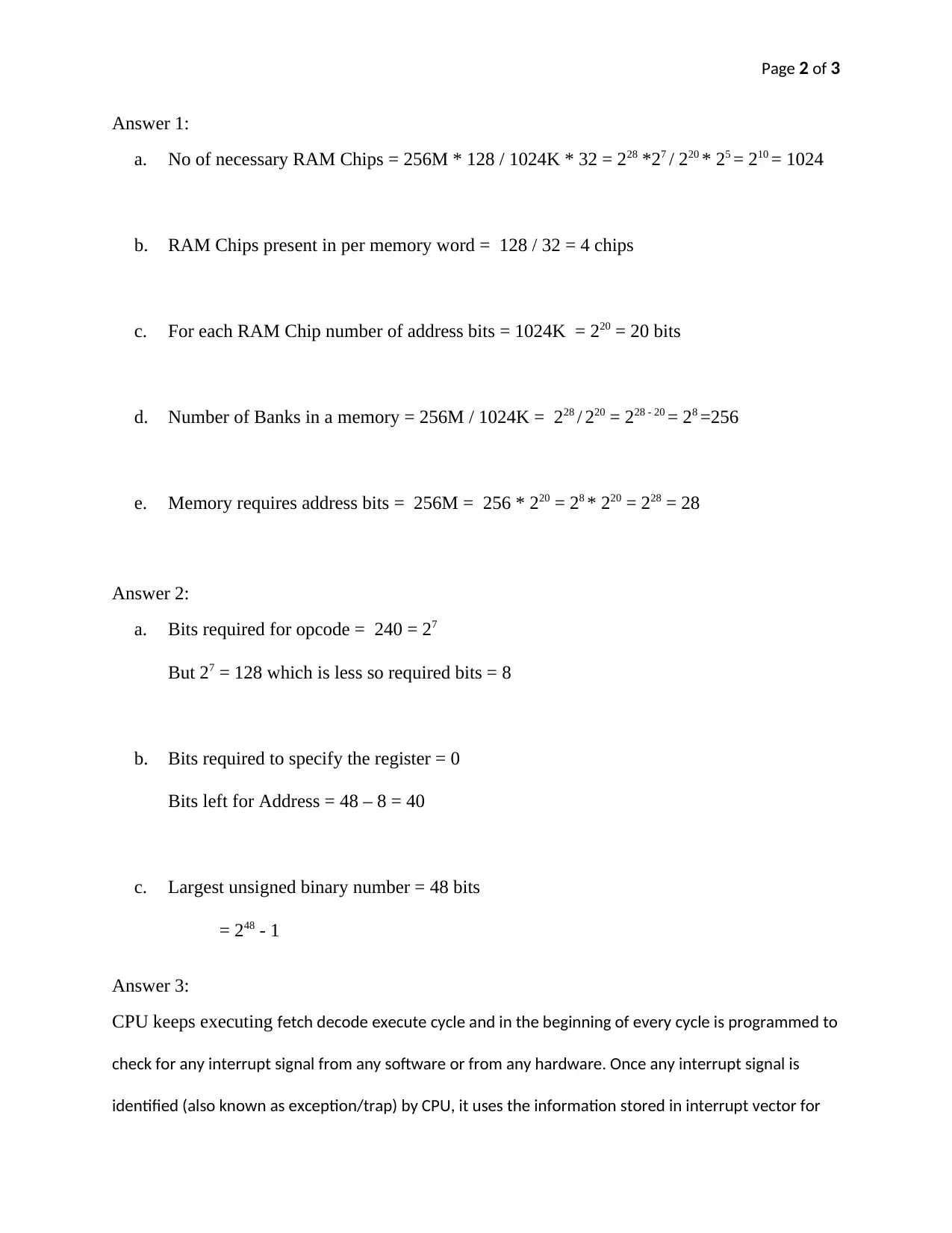
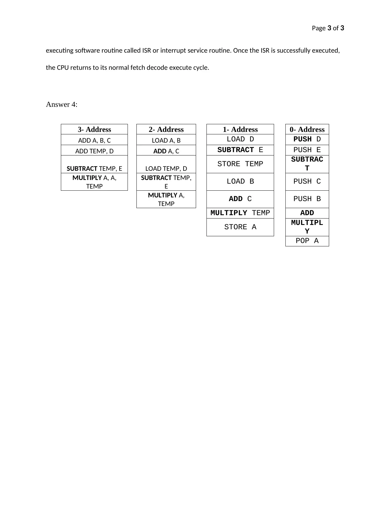
This assignment solution for ITC544 addresses key concepts in computer architecture. The solution calculates the number of RAM chips, address bits, and the number of banks required for a given memory configuration. It also determines the bits required for opcode and registers, and the largest unsigned binary number. The solution further explains the CPU's fetch-decode-execute cycle, including the handling of interrupt signals and the execution of interrupt service routines (ISRs). Finally, the solution provides examples of assembly language code for different addressing modes, including 3-address, 2-address, 1-address, and 0-address formats, illustrating how various operations are performed at the assembly level. This assignment covers crucial aspects of computer organization and assembly language programming.
Document Page
Page 1 of 3
Assignment 2: MARIE & ISA
Student ID
Student Name
ITC544
tabler-icon-diamond-filled.svg

Paraphrase This Document

Need a fresh take? Get an instant paraphrase of this document with our AI Paraphraser
Document Page
Page 2 of 3
Answer 1:
a. No of necessary RAM Chips = 256M * 128 / 1024K * 32 = 228 *27 / 220 * 25 = 210 = 1024
b. RAM Chips present in per memory word = 128 / 32 = 4 chips
c. For each RAM Chip number of address bits = 1024K = 220 = 20 bits
d. Number of Banks in a memory = 256M / 1024K = 228 / 220 = 228 - 20 = 28 =256
e. Memory requires address bits = 256M = 256 * 220 = 28 * 220 = 228 = 28
Answer 2:
a. Bits required for opcode = 240 = 27
But 27 = 128 which is less so required bits = 8
b. Bits required to specify the register = 0
Bits left for Address = 48 – 8 = 40
c. Largest unsigned binary number = 48 bits
= 248 - 1
Answer 3:
CPU keeps executing fetch decode execute cycle and in the beginning of every cycle is programmed to
check for any interrupt signal from any software or from any hardware. Once any interrupt signal is
identified (also known as exception/trap) by CPU, it uses the information stored in interrupt vector for
Document Page
Page 3 of 3
executing software routine called ISR or interrupt service routine. Once the ISR is successfully executed,
the CPU returns to its normal fetch decode execute cycle.
Answer 4:
3- Address 2- Address 1- Address 0- Address
ADD A, B, C LOAD A, B LOAD D PUSH D
ADD TEMP, D ADD A, C SUBTRACT E PUSH E
SUBTRACT TEMP, E LOAD TEMP, D STORE TEMP SUBTRAC
T
MULTIPLY A, A,
TEMP
SUBTRACT TEMP,
E LOAD B PUSH C
MULTIPLY A,
TEMP ADD C PUSH B
MULTIPLY TEMP ADD
STORE A MULTIPL
Y
POP A
chevron_up_icon
1 out of 3
circle_padding
hide_on_mobile
zoom_out_icon
[object Object]