ITC556 Database Systems: Comprehensive ER Diagram Modelling Project

Verified

Added on  2024/05/20

|9
|589
|180
Project
AI Summary
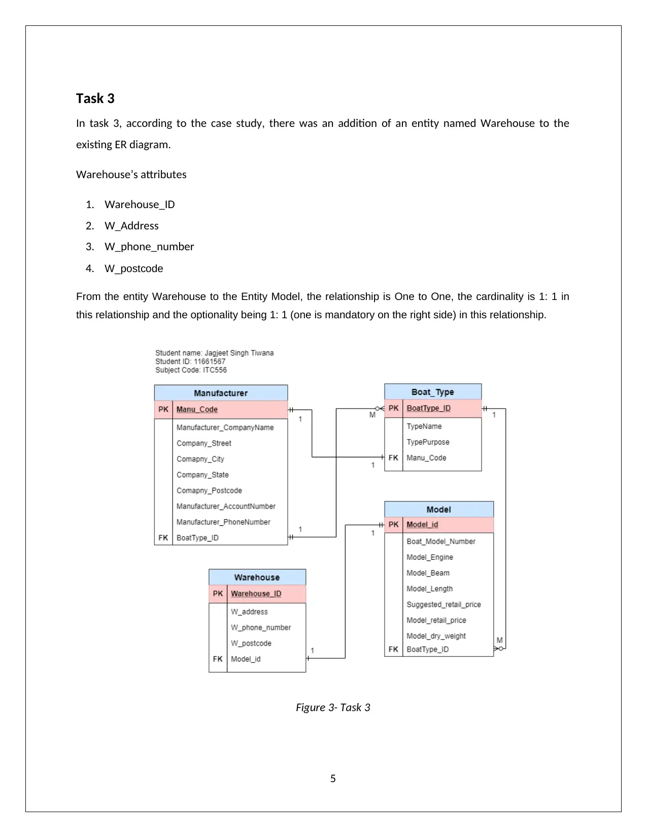
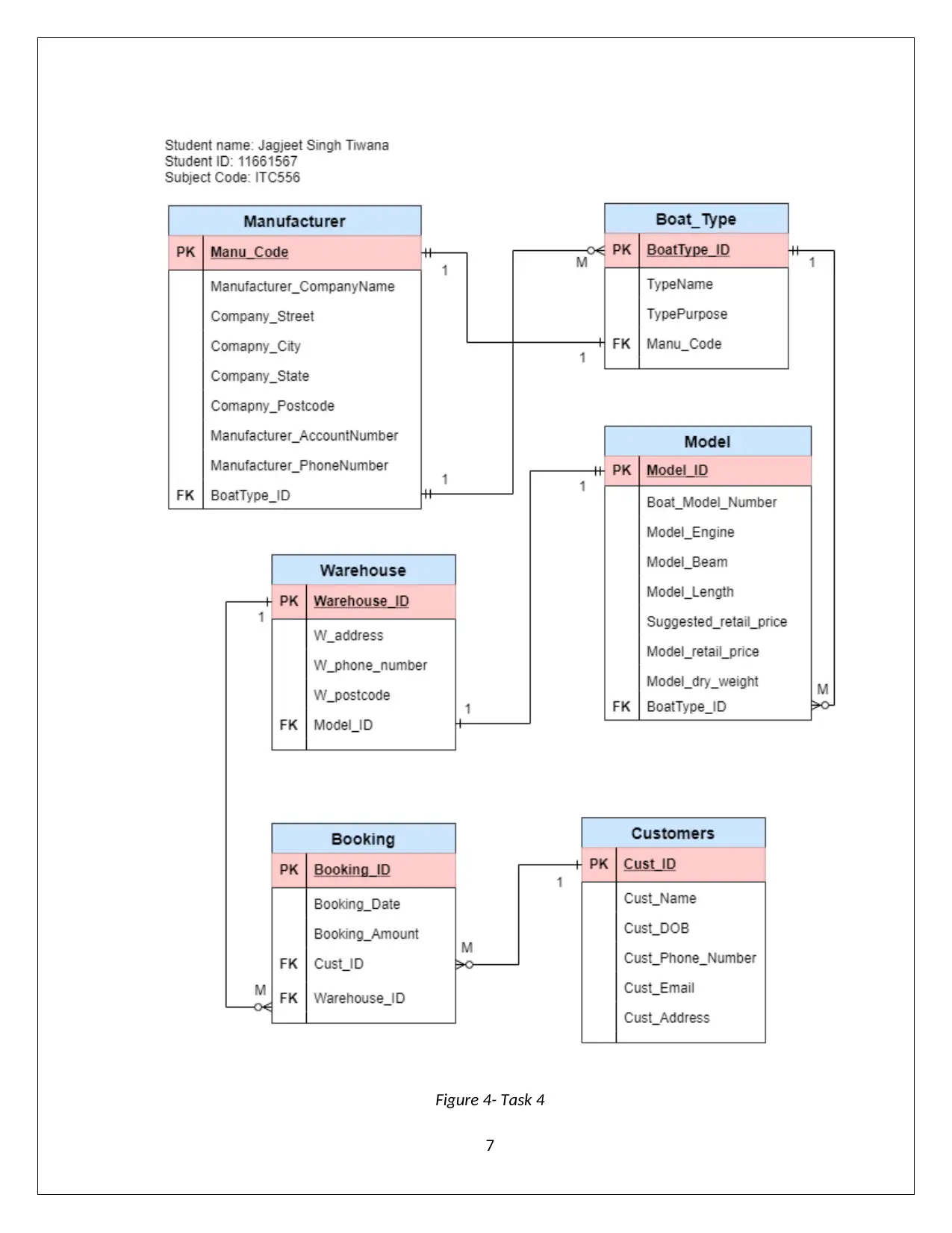
This project focuses on Entity-Relationship (ER) diagram modelling within the context of database systems, specifically for the ITC556 course. The project involves creating and evolving an ER diagram through several stages. Initially, the project establishes entities for 'Manufacturer' and 'Boat_Type' with their respective attributes and relationships. It then expands the model by incorporating a 'Model' entity, detailing its attributes and relationships with existing entities. Further development includes the addition of a 'Warehouse' entity and its connection to the 'Model' entity. Finally, the project integrates 'Customers' and 'Booking' entities, defining their attributes and relationships with other entities in the diagram. The project comprehensively demonstrates the process of database modelling and design, illustrating cardinality and optionality constraints between entities.
Document Page
ITC556 - Database Systems
Assessment 2- Modelling
Student Name: Jagjeet Singh Tiwana
Student ID: 11661567
tabler-icon-diamond-filled.svg

Paraphrase This Document

Need a fresh take? Get an instant paraphrase of this document with our AI Paraphraser
Document Page
Table of Contents
Task 1..........................................................................................................................................................2
Task 2..........................................................................................................................................................4
Task 3..........................................................................................................................................................5
Task 4..........................................................................................................................................................6
References...................................................................................................................................................8
1
Document Page
Task 1
In task 1, according to the case study, two entities were created which are Manufacturer and Boat_Type.
Manufacturer’s Attributes
1. Manu_Code
2. Manufacturer_CompanyName
3. Company_Street
4. Company_City
5. Company_State
6. Company_Postcode
7. Manufacturer_PhoneNumber
8. Manufacturer_AccountNumber.
Boat_Type’s attributes
1. BoatType_ID
2. TypeName
3. TypePurpose (Holowczak.com Tutorials, 2018)
From the entity Manufacturer to the entity Boat_Type, the relationship is One to Many, the cardinality is 1:
M in this relationship and the optionality being 1: M (many sides is optional) in this relationship (Thomas,
2005). From the entity Boat_Type to the entity Manufacturer, the relationship is One to One, the
cardinality is 1: 1 in this relationship and the optionality being 1: 1 (one is mandatory on the right side) in
this relationship.
2
Document Page
Figure 1- Task1
3
tabler-icon-diamond-filled.svg

Paraphrase This Document

Need a fresh take? Get an instant paraphrase of this document with our AI Paraphraser
Document Page
Task 2
In task 2, there was an addition of an entity named Model to the existing ER diagram.
Model’s attributes
1. Model_ID
2. Boat_Model_Number
3. Model_Engine
4. Model_Length
5. Model_Beam
6. Suggested_retail_price
7. Model_retail_price
8. Model_dry_weight
From the entity Boat_Type to the Entity Model, the relationship is One to Many, the cardinality is 1: M in
this relationship and the optionality being 1: M (many sides is optional) in this relationship.
Figure 2- Task 2
4
Document Page
Task 3
In task 3, according to the case study, there was an addition of an entity named Warehouse to the
existing ER diagram.
Warehouse’s attributes
1. Warehouse_ID
2. W_Address
3. W_phone_number
4. W_postcode
From the entity Warehouse to the Entity Model, the relationship is One to One, the cardinality is 1: 1 in
this relationship and the optionality being 1: 1 (one is mandatory on the right side) in this relationship.
Figure 3- Task 3
5
Document Page
Task 4
In task 4, according to the case study, two entities were created which are Customers and Booking and
added to the existing diagram.
Customers’ attributes
1. Cust_Id
2. Cust_Name
3. Cust_DOB
4. Cust_Phone_Number
5. Cust_Email
6. Cust_Address
Booking’s attributes
1. Booking_ID
2. Booking_Date
3. Booking_Amount
From the entity Customer to the entity Booking, the relationship is One to Many, the cardinality is 1: M in
this relationship and the optionality being 1: M (many sides is optional) in this relationship.
From the entity Warehouse to the entity Booking, the relationship is One to Many, the cardinality is 1: M in
this relationship and the optionality being 1: M (many sides is optional) in this relationship.
6
tabler-icon-diamond-filled.svg

Paraphrase This Document

Need a fresh take? Get an instant paraphrase of this document with our AI Paraphraser
Document Page
Figure 4- Task 4
7
Document Page
References
Holowczak.com Tutorials. (2018). E-R Diagrams. Retrieved from http://holowczak.com/entity-
relationship-modeling-in-database-management-systems/3/
Thomas. (2005). Relationship degree, cardinality and optionality [Blog comment]. Retrieved from
http://n12503.blogspot.in/2005/11/relationship-degree-cardinality-and.html
8
chevron_up_icon
1 out of 9
circle_padding
hide_on_mobile
zoom_out_icon
[object Object]