Performance Analysis of Kalina Cycle via EES Simulation
VerifiedAdded on 2022/08/17
|11
|1847
|9
Report
AI Summary
This report presents a simulation of the Kalina cycle, a thermodynamic power cycle designed to exploit low-temperature heat sources, using the EES software. The study investigates the cycle's performance, focusing on the impact of various parameters on thermal efficiency. The report explores the influence of maximum pressure, ammonia concentration, source temperature, and turbine efficiency. Key findings indicate that the HRVG temperature is the dominant factor affecting the cycle's efficiency, while the separator pressure remains constant for a given temperature. The report concludes that increasing the source temperature and turbine efficiency generally enhances thermal efficiency, providing insights into optimizing the Kalina cycle for low-temperature applications. The analysis includes graphical representations of the results and a detailed discussion of the findings, supported by relevant references.

SIMULATION OF KALINA CYCLE USING EES
Paraphrase This Document
Need a fresh take? Get an instant paraphrase of this document with our AI Paraphraser
Table of Contents
Introduction......................................................................................................................................2
Kalina cycle.....................................................................................................................................2
Cycle Performance Analysis............................................................................................................3
Assumptions.................................................................................................................................3
Nomenclatures.............................................................................................................................4
Energy Equations In Galina Cycle...............................................................................................4
Results and Discussion....................................................................................................................5
Conclusion.......................................................................................................................................8
References........................................................................................................................................9
1
Introduction
Kalina cycle was formulated by Kalina to exploit heat at low temperatures. This is a new
type of thermodynamic power cycle that is based on using the characteristics of the dual mixture
of ammonia and water to trap the heat at low temperatures, therefore, putting waste heat to
efficient use. Compared to other cycles, this cycle is preferred for recovery of heat at low
temperatures due to the non-azeotropic characteristics of the ammonia-water mixture. In this
paper, we will study the thermodynamic behaviour of this cycle for low-temperature purposes.
Kalina cycle
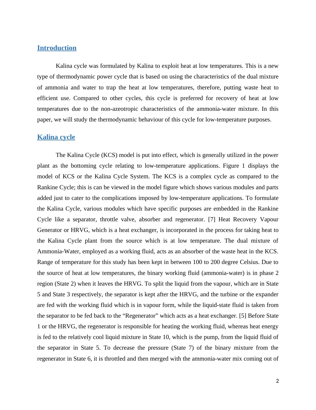
The Kalina Cycle (KCS) model is put into effect, which is generally utilized in the power
plant as the bottoming cycle relating to low-temperature applications. Figure 1 displays the
model of KCS or the Kalina Cycle System. The KCS is a complex cycle as compared to the
Rankine Cycle; this is can be viewed in the model figure which shows various modules and parts
added just to cater to the complications imposed by low-temperature applications. To formulate
the Kalina Cycle, various modules which have specific purposes are embedded in the Rankine
Cycle like a separator, throttle valve, absorber and regenerator. [7] Heat Recovery Vapour
Generator or HRVG, which is a heat exchanger, is incorporated in the process for taking heat to
the Kalina Cycle plant from the source which is at low temperature. The dual mixture of
Ammonia-Water, employed as a working fluid, acts as an absorber of the waste heat in the KCS.
Range of temperature for this study has been kept in between 100 to 200 degree Celsius. Due to
the source of heat at low temperatures, the binary working fluid (ammonia-water) is in phase 2
region (State 2) when it leaves the HRVG. To split the liquid from the vapour, which are in State
5 and State 3 respectively, the separator is kept after the HRVG, and the turbine or the expander
are fed with the working fluid which is in vapour form, while the liquid-state fluid is taken from
the separator to be fed back to the “Regenerator” which acts as a heat exchanger. [5] Before State
1 or the HRVG, the regenerator is responsible for heating the working fluid, whereas heat energy
is fed to the relatively cool liquid mixture in State 10, which is the pump, from the liquid fluid of
the separator in State 5. To decrease the pressure (State 7) of the binary mixture from the
regenerator in State 6, it is throttled and then merged with the ammonia-water mix coming out of
2
Kalina cycle was formulated by Kalina to exploit heat at low temperatures. This is a new
type of thermodynamic power cycle that is based on using the characteristics of the dual mixture
of ammonia and water to trap the heat at low temperatures, therefore, putting waste heat to
efficient use. Compared to other cycles, this cycle is preferred for recovery of heat at low
temperatures due to the non-azeotropic characteristics of the ammonia-water mixture. In this
paper, we will study the thermodynamic behaviour of this cycle for low-temperature purposes.
Kalina cycle
The Kalina Cycle (KCS) model is put into effect, which is generally utilized in the power
plant as the bottoming cycle relating to low-temperature applications. Figure 1 displays the
model of KCS or the Kalina Cycle System. The KCS is a complex cycle as compared to the
Rankine Cycle; this is can be viewed in the model figure which shows various modules and parts
added just to cater to the complications imposed by low-temperature applications. To formulate
the Kalina Cycle, various modules which have specific purposes are embedded in the Rankine
Cycle like a separator, throttle valve, absorber and regenerator. [7] Heat Recovery Vapour
Generator or HRVG, which is a heat exchanger, is incorporated in the process for taking heat to
the Kalina Cycle plant from the source which is at low temperature. The dual mixture of
Ammonia-Water, employed as a working fluid, acts as an absorber of the waste heat in the KCS.
Range of temperature for this study has been kept in between 100 to 200 degree Celsius. Due to
the source of heat at low temperatures, the binary working fluid (ammonia-water) is in phase 2
region (State 2) when it leaves the HRVG. To split the liquid from the vapour, which are in State
5 and State 3 respectively, the separator is kept after the HRVG, and the turbine or the expander
are fed with the working fluid which is in vapour form, while the liquid-state fluid is taken from
the separator to be fed back to the “Regenerator” which acts as a heat exchanger. [5] Before State
1 or the HRVG, the regenerator is responsible for heating the working fluid, whereas heat energy
is fed to the relatively cool liquid mixture in State 10, which is the pump, from the liquid fluid of
the separator in State 5. To decrease the pressure (State 7) of the binary mixture from the
regenerator in State 6, it is throttled and then merged with the ammonia-water mix coming out of
2
⊘ This is a preview!⊘
Do you want full access?
Subscribe today to unlock all pages.
Trusted by 1+ million students worldwide
the turbine (State 4) in the absorber. For the dispensation of heat, achieved through a heat
exchanger, from the binary ammonia-water mixture after the absorber in State 8, a condenser is
also set-up. Cooling water is the mode of heat absorption within the condenser and is perpetually
circulated to absorb the heat from the mixture. The pump then pulls the liquid working fluid in
State 9. [2]
Figure 1 Kalina Cycle System Flow Model
Cycle Performance Analysis
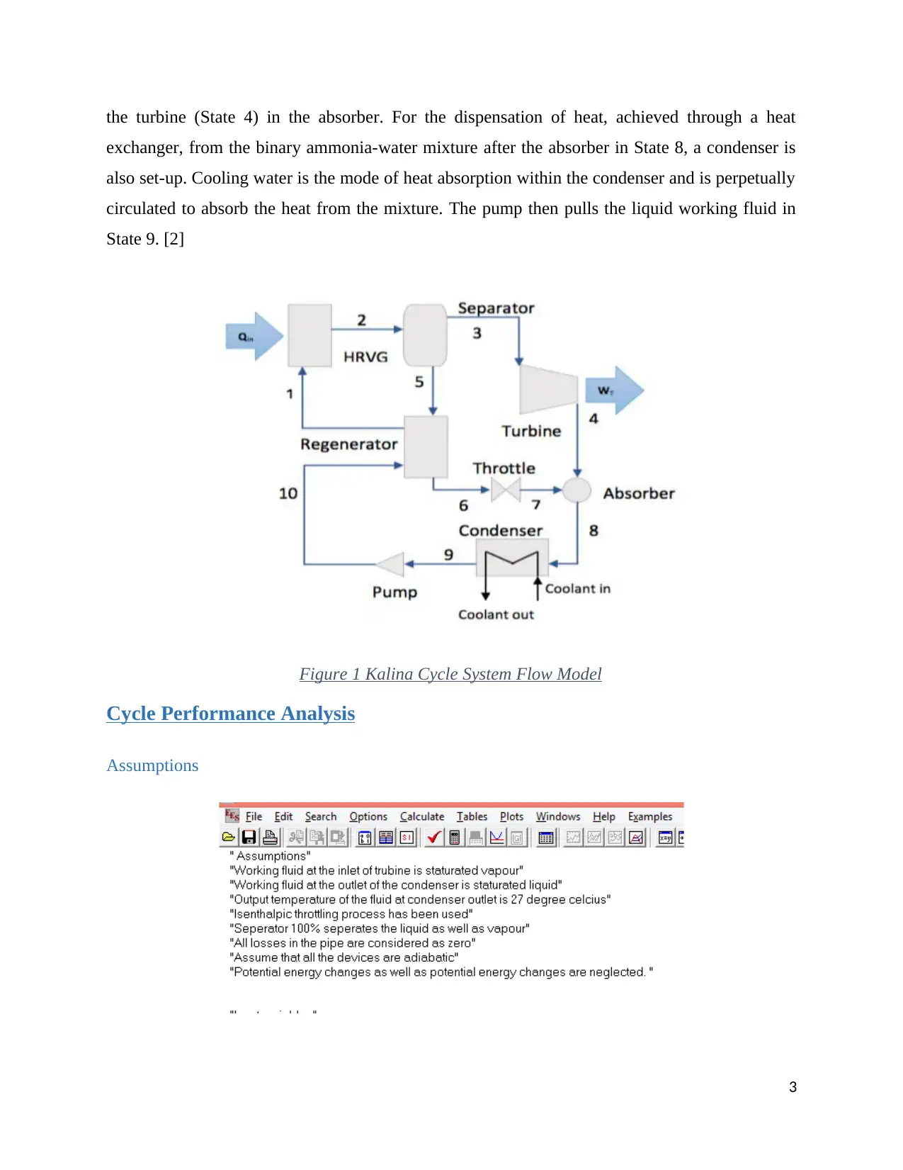
Assumptions
3
exchanger, from the binary ammonia-water mixture after the absorber in State 8, a condenser is
also set-up. Cooling water is the mode of heat absorption within the condenser and is perpetually
circulated to absorb the heat from the mixture. The pump then pulls the liquid working fluid in
State 9. [2]
Figure 1 Kalina Cycle System Flow Model
Cycle Performance Analysis
Assumptions
3
Paraphrase This Document
Need a fresh take? Get an instant paraphrase of this document with our AI Paraphraser
Nomenclatures
Parameters considered
In this project, we considered four major parameters and measured how it shows the
impact on the overall thermal efficiency of the cycle. And they are listed below.
Maximum pressure (Pmax)
The concentration of Ammonia or fraction of ammonia in the initial feed. (X_NH3)
The temperature of the source (Temp_source)
The efficiency of the turbine (Efficency_turbine)
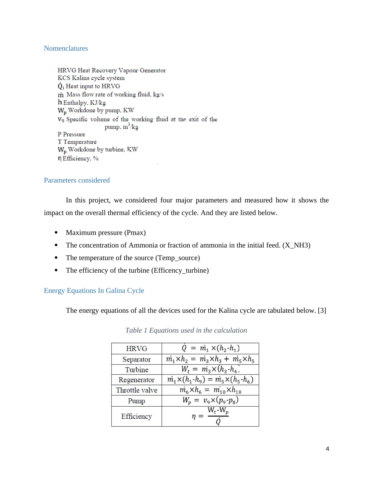
Energy Equations In Galina Cycle
The energy equations of all the devices used for the Kalina cycle are tabulated below. [3]
Table 1 Equations used in the calculation
4
Parameters considered
In this project, we considered four major parameters and measured how it shows the
impact on the overall thermal efficiency of the cycle. And they are listed below.
Maximum pressure (Pmax)
The concentration of Ammonia or fraction of ammonia in the initial feed. (X_NH3)
The temperature of the source (Temp_source)
The efficiency of the turbine (Efficency_turbine)
Energy Equations In Galina Cycle
The energy equations of all the devices used for the Kalina cycle are tabulated below. [3]
Table 1 Equations used in the calculation
4
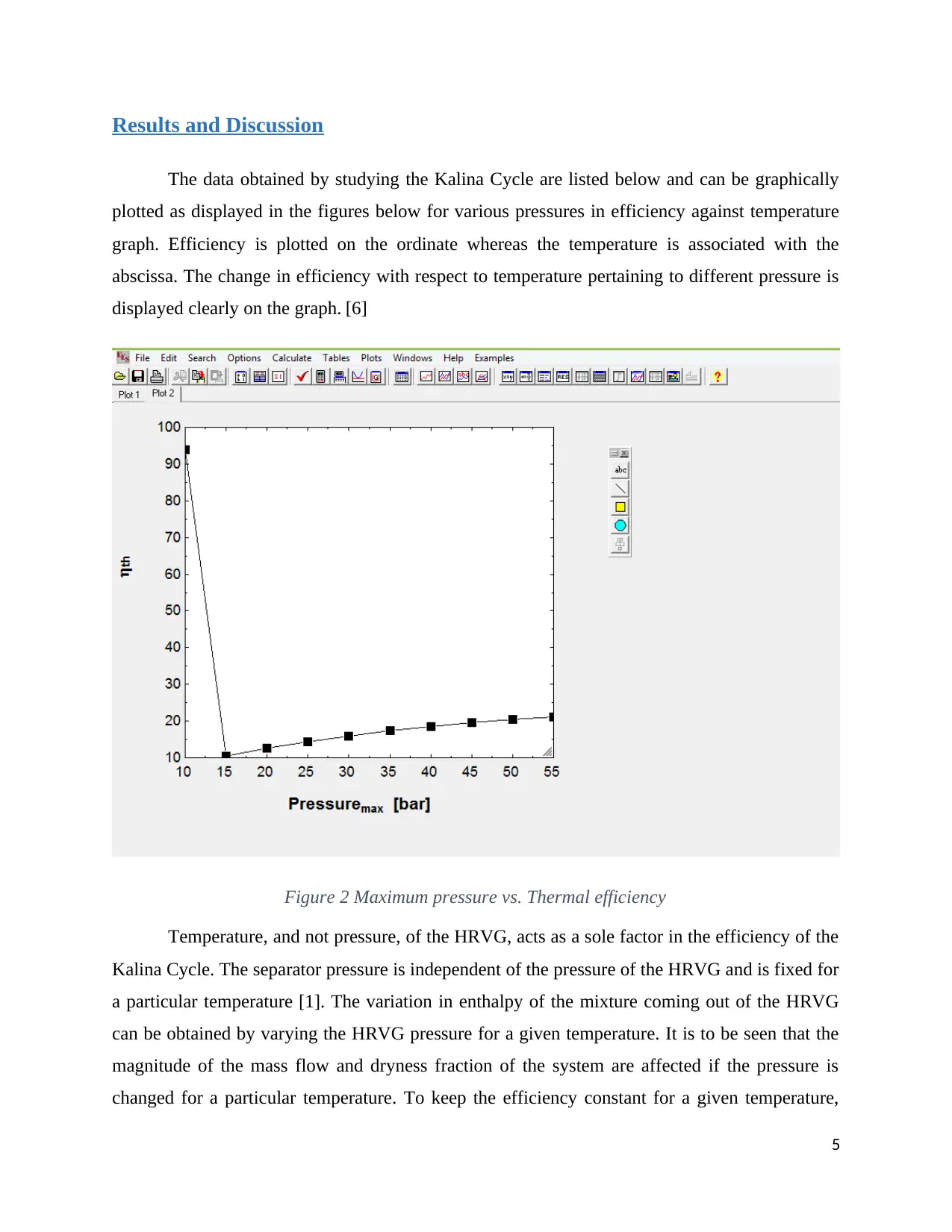
Results and Discussion
The data obtained by studying the Kalina Cycle are listed below and can be graphically
plotted as displayed in the figures below for various pressures in efficiency against temperature
graph. Efficiency is plotted on the ordinate whereas the temperature is associated with the
abscissa. The change in efficiency with respect to temperature pertaining to different pressure is
displayed clearly on the graph. [6]
Figure 2 Maximum pressure vs. Thermal efficiency
Temperature, and not pressure, of the HRVG, acts as a sole factor in the efficiency of the
Kalina Cycle. The separator pressure is independent of the pressure of the HRVG and is fixed for
a particular temperature [1]. The variation in enthalpy of the mixture coming out of the HRVG
can be obtained by varying the HRVG pressure for a given temperature. It is to be seen that the
magnitude of the mass flow and dryness fraction of the system are affected if the pressure is
changed for a particular temperature. To keep the efficiency constant for a given temperature,
5
⊘ This is a preview!⊘
Do you want full access?
Subscribe today to unlock all pages.
Trusted by 1+ million students worldwide
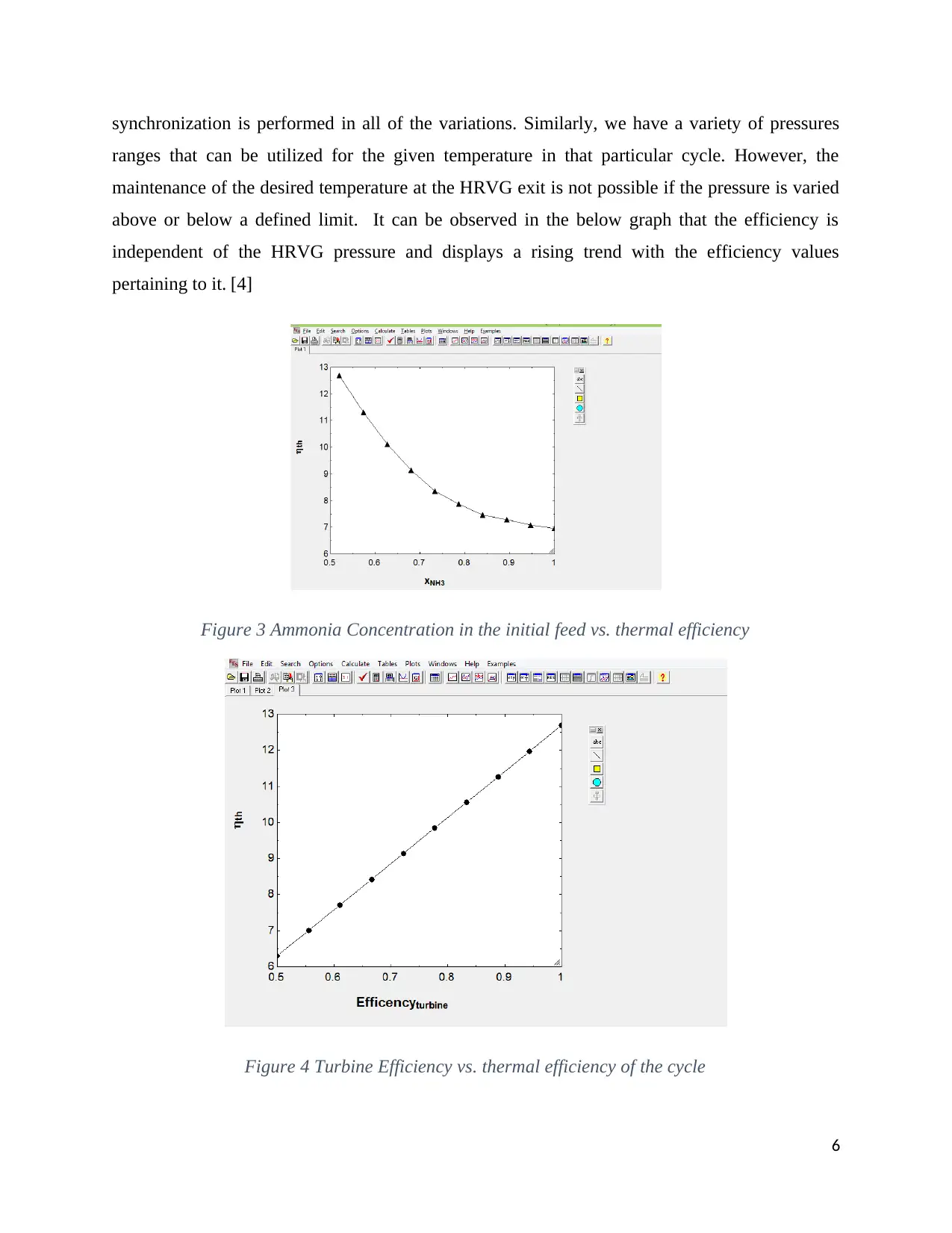
synchronization is performed in all of the variations. Similarly, we have a variety of pressures
ranges that can be utilized for the given temperature in that particular cycle. However, the
maintenance of the desired temperature at the HRVG exit is not possible if the pressure is varied
above or below a defined limit. It can be observed in the below graph that the efficiency is
independent of the HRVG pressure and displays a rising trend with the efficiency values
pertaining to it. [4]
Figure 3 Ammonia Concentration in the initial feed vs. thermal efficiency
Figure 4 Turbine Efficiency vs. thermal efficiency of the cycle
6
Paraphrase This Document
Need a fresh take? Get an instant paraphrase of this document with our AI Paraphraser
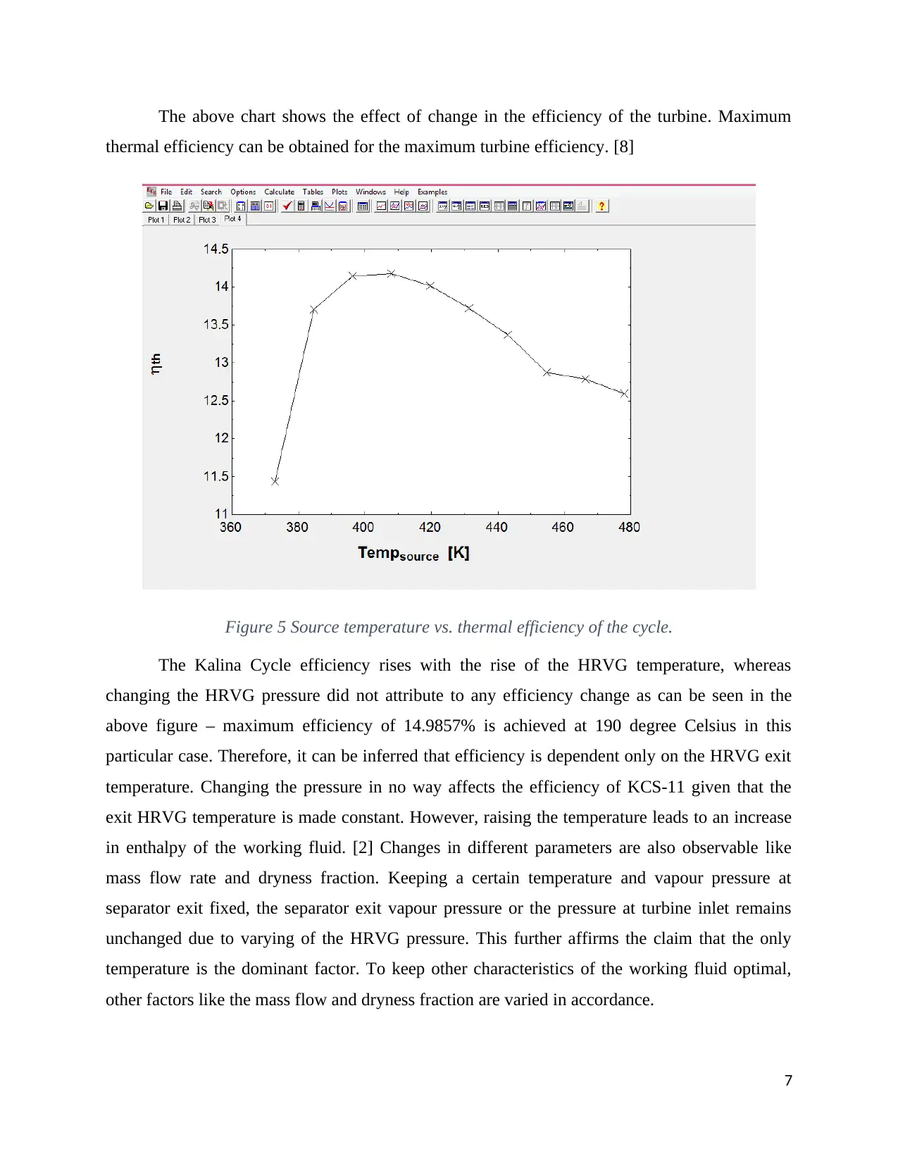
The above chart shows the effect of change in the efficiency of the turbine. Maximum
thermal efficiency can be obtained for the maximum turbine efficiency. [8]
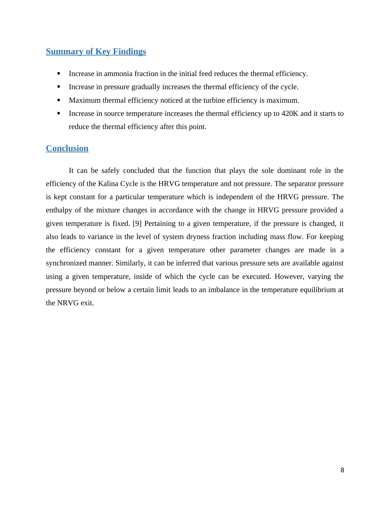
Figure 5 Source temperature vs. thermal efficiency of the cycle.
The Kalina Cycle efficiency rises with the rise of the HRVG temperature, whereas
changing the HRVG pressure did not attribute to any efficiency change as can be seen in the
above figure – maximum efficiency of 14.9857% is achieved at 190 degree Celsius in this
particular case. Therefore, it can be inferred that efficiency is dependent only on the HRVG exit
temperature. Changing the pressure in no way affects the efficiency of KCS-11 given that the
exit HRVG temperature is made constant. However, raising the temperature leads to an increase
in enthalpy of the working fluid. [2] Changes in different parameters are also observable like
mass flow rate and dryness fraction. Keeping a certain temperature and vapour pressure at
separator exit fixed, the separator exit vapour pressure or the pressure at turbine inlet remains
unchanged due to varying of the HRVG pressure. This further affirms the claim that the only
temperature is the dominant factor. To keep other characteristics of the working fluid optimal,
other factors like the mass flow and dryness fraction are varied in accordance.
7
thermal efficiency can be obtained for the maximum turbine efficiency. [8]
Figure 5 Source temperature vs. thermal efficiency of the cycle.
The Kalina Cycle efficiency rises with the rise of the HRVG temperature, whereas
changing the HRVG pressure did not attribute to any efficiency change as can be seen in the
above figure – maximum efficiency of 14.9857% is achieved at 190 degree Celsius in this
particular case. Therefore, it can be inferred that efficiency is dependent only on the HRVG exit
temperature. Changing the pressure in no way affects the efficiency of KCS-11 given that the
exit HRVG temperature is made constant. However, raising the temperature leads to an increase
in enthalpy of the working fluid. [2] Changes in different parameters are also observable like
mass flow rate and dryness fraction. Keeping a certain temperature and vapour pressure at
separator exit fixed, the separator exit vapour pressure or the pressure at turbine inlet remains
unchanged due to varying of the HRVG pressure. This further affirms the claim that the only
temperature is the dominant factor. To keep other characteristics of the working fluid optimal,
other factors like the mass flow and dryness fraction are varied in accordance.
7
Summary of Key Findings
Increase in ammonia fraction in the initial feed reduces the thermal efficiency.
Increase in pressure gradually increases the thermal efficiency of the cycle.
Maximum thermal efficiency noticed at the turbine efficiency is maximum.
Increase in source temperature increases the thermal efficiency up to 420K and it starts to
reduce the thermal efficiency after this point.
Conclusion
It can be safely concluded that the function that plays the sole dominant role in the
efficiency of the Kalina Cycle is the HRVG temperature and not pressure. The separator pressure
is kept constant for a particular temperature which is independent of the HRVG pressure. The
enthalpy of the mixture changes in accordance with the change in HRVG pressure provided a
given temperature is fixed. [9] Pertaining to a given temperature, if the pressure is changed, it
also leads to variance in the level of system dryness fraction including mass flow. For keeping
the efficiency constant for a given temperature other parameter changes are made in a
synchronized manner. Similarly, it can be inferred that various pressure sets are available against
using a given temperature, inside of which the cycle can be executed. However, varying the
pressure beyond or below a certain limit leads to an imbalance in the temperature equilibrium at
the NRVG exit.
8
⊘ This is a preview!⊘
Do you want full access?
Subscribe today to unlock all pages.
Trusted by 1+ million students worldwide
References
[1]R. Shankar and T. Srinivas, "Options in Kalina Cycle Systems", Energy Procedia, vol. 90, pp.
260-266, 2016. Available: 10.1016/j.egypro.2016.11.193.
[2]C. Koroneos and D. Rovas, "Exergy analysis of geothermal electricity using the Kalina
cycle", International Journal of Exergy, vol. 12, no. 1, p. 54, 2013. Available:
10.1504/ijex.2013.052543.
[3]P. Lolos and E. Rogdakis, "A Kalina power cycle driven by renewable energy
sources", Energy, vol. 34, no. 4, pp. 457-464, 2009. Available:
10.1016/j.energy.2008.12.011.
[4]"Thermodynamic Analysis of Kalina Cycle", International Journal of Science and Research
(IJSR), vol. 5, no. 3, pp. 2244-2249, 2016. Available: 10.21275/v5i3.nov162434.
[5]R. Bahrampoury and A. Behbahaninia, "Thermodynamic optimization and thermoeconomic
analysis of four double pressure Kalina cycles driven from Kalina cycle system 11", Energy
Conversion and Management, vol. 152, pp. 110-123, 2017. Available:
10.1016/j.enconman.2017.09.046.
[6]M. Mirolli, "Cementing Kalina cycle effectiveness", IEEE Industry Applications Magazine,
vol. 12, no. 4, pp. 60-64, 2006. Available: 10.1109/mia.2006.1678332.
[7]O. Arslan, "Power generation from medium temperature geothermal resources: ANN-based
optimization of Kalina cycle system-34", Energy, vol. 36, no. 5, pp. 2528-2534, 2011.
Available: 10.1016/j.energy.2011.01.045.
[8]E. Wang and Z. Yu, "A numerical analysis of a composition-adjustable Kalina cycle power
plant for power generation from low-temperature geothermal sources", Applied Energy, vol.
180, pp. 834-848, 2016. Available: 10.1016/j.apenergy.2016.08.032.
[9]V. Zare and V. Palideh, "Employing thermoelectric generator for power generation
enhancement in a Kalina cycle driven by low-grade geothermal energy", Applied Thermal
9
Paraphrase This Document
Need a fresh take? Get an instant paraphrase of this document with our AI Paraphraser

Engineering, vol. 130, pp. 418-428, 2018. Available:
10.1016/j.applthermaleng.2017.10.160.
10
10.1016/j.applthermaleng.2017.10.160.
10
1 out of 11
Related Documents


Your All-in-One AI-Powered Toolkit for Academic Success.
+13062052269
info@desklib.com
Available 24*7 on WhatsApp / Email
![[object Object]](/_next/static/media/star-bottom.7253800d.svg)
Unlock your academic potential
Copyright © 2020–2025 A2Z Services. All Rights Reserved. Developed and managed by ZUCOL.