Comprehensive Case Study: Information System for Kangaroo Taxi
VerifiedAdded on 2023/01/11
|14
|2528
|43
Case Study
AI Summary
This case study analyzes the information system development for Kangaroo Taxi, an online taxi service operating in Australia. The report begins with an introduction to information system development and data modeling, followed by an outline of the case study focusing on the online taxi service's website and user registration. The core of the study involves various UML diagrams, including use case diagrams (for user registration and cab bookings), a use case diagram (summarizing interactions between users and the system), an entity relationship diagram (illustrating the relationships between entities like drivers, cars, and customers), a class diagram (depicting classes and objects), sequence diagrams (showing the order of operations for admin, agent, and customer interactions), and an activity diagram (describing the flow of activities within the system). The diagrams are designed to provide a comprehensive understanding of the system's design and functionality, contributing to the overall objective of providing efficient online taxi services. The conclusion summarizes the key findings and the effectiveness of the proposed system development strategies.
Case Study
Paraphrase This Document
Need a fresh take? Get an instant paraphrase of this document with our AI Paraphraser
Table of Contents
Introduction......................................................................................................................................3
Outline of case study..............................................................................................................3
Use case Diagram...................................................................................................................3
Use Case diagram...................................................................................................................6
Entity relationship diagram....................................................................................................7
Class diagram.........................................................................................................................9
Sequence Diagram..................................................................................................................9
Activity diagram...................................................................................................................12
Conclusion.....................................................................................................................................13
References......................................................................................................................................14
Introduction
The process which comprises of work activities and organisational settings that are being
assisted through new information system for either expanding either existing or modifying it is
referred to as information system development. Data modelling refers to process that is related
with creating data models for storing data within them (Awasthi and Omrani, 2019). The steps
which are being used for formations, formulate plans along with controlling process for
developing information system for having computerised methods is defined as system
development approach. There exist wide range of concepts which are being utilised for
development of system; they are users, system testing, interface, maintenance, deployment, etc.
For understanding this conception, Kangaroo Taxi is taken who have started rendering their
online taxi services around Australia. This report comprises of distinct diagrams for furnishing
adequate information related with system of organisation.
Outline of case study
Kangaroo Taxi is delivering services in Australia for their users by providing them with
online taxi services. For this, they have developed their website that can be accessed by
registering in it through usage of mobile devices. Users need to login into the system by making
use of their credentials like username, contact number, address and other details which are being
asked. This has to be done only one time as at next time users need to directly enter their
username as well as password for having essential details related with services they need to have.
Here, user can check all the essential details related with taxis, fares to different destination as
well as they have option to choose the payment method as per their convenience. For the
security of passengers all the essential details of their drivers are being given when they have
made bookings.
Use case Diagram
The primary form of software or system needs for new software programs which are
underdeveloped is referred to as UML case diagram. They are liable for specifying anticipated
behaviour and it will not furnish actual method with respect to how it is being done or happening
(De Rooij, Mannak and Janowicz-Panjaitan, 2019). They are being specified either in textual or
visual form. Basically, it will aid Kangaroo Taxi to design a system from perspectives of their
end users. This denotes effectual technique to interact with users in terms of visualising the
⊘ This is a preview!⊘
Do you want full access?
Subscribe today to unlock all pages.
Trusted by 1+ million students worldwide
external system behaviour. Generally, it is a graphical depiction which is liable for interacting
with distinct entities within the system. It will be used for identification, clarification along with
organisation of system requirements. In this context, system implies something which is being
developed and operated such as sending emails related with offers given to their customers for
captivating them so that they opt for services that are being furnished by Kangaroo Taxi. UML
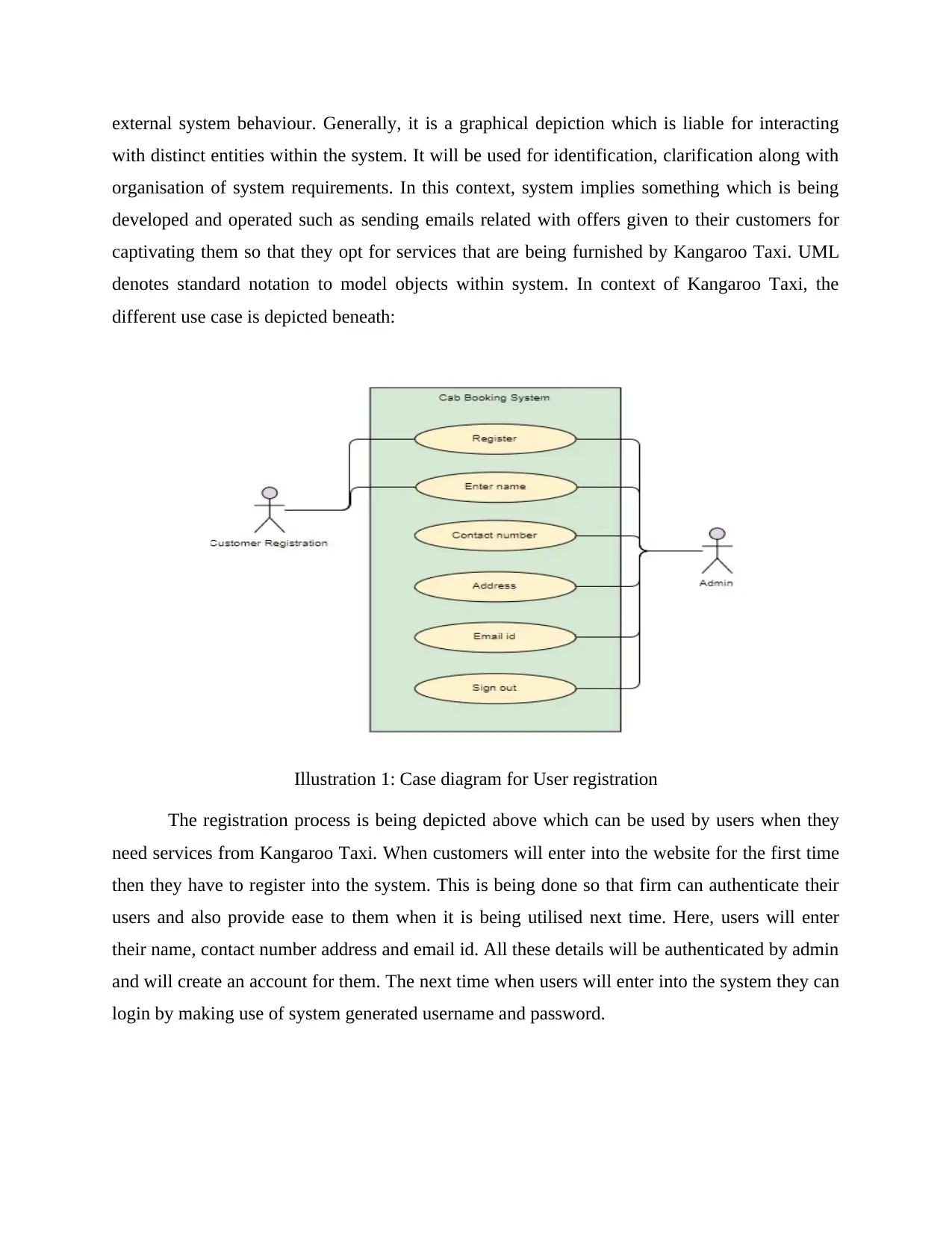
denotes standard notation to model objects within system. In context of Kangaroo Taxi, the
different use case is depicted beneath:
Illustration 1: Case diagram for User registration
The registration process is being depicted above which can be used by users when they
need services from Kangaroo Taxi. When customers will enter into the website for the first time
then they have to register into the system. This is being done so that firm can authenticate their
users and also provide ease to them when it is being utilised next time. Here, users will enter
their name, contact number address and email id. All these details will be authenticated by admin
and will create an account for them. The next time when users will enter into the system they can
login by making use of system generated username and password.
with distinct entities within the system. It will be used for identification, clarification along with
organisation of system requirements. In this context, system implies something which is being
developed and operated such as sending emails related with offers given to their customers for
captivating them so that they opt for services that are being furnished by Kangaroo Taxi. UML
denotes standard notation to model objects within system. In context of Kangaroo Taxi, the
different use case is depicted beneath:
Illustration 1: Case diagram for User registration
The registration process is being depicted above which can be used by users when they
need services from Kangaroo Taxi. When customers will enter into the website for the first time
then they have to register into the system. This is being done so that firm can authenticate their
users and also provide ease to them when it is being utilised next time. Here, users will enter
their name, contact number address and email id. All these details will be authenticated by admin
and will create an account for them. The next time when users will enter into the system they can
login by making use of system generated username and password.
Paraphrase This Document
Need a fresh take? Get an instant paraphrase of this document with our AI Paraphraser
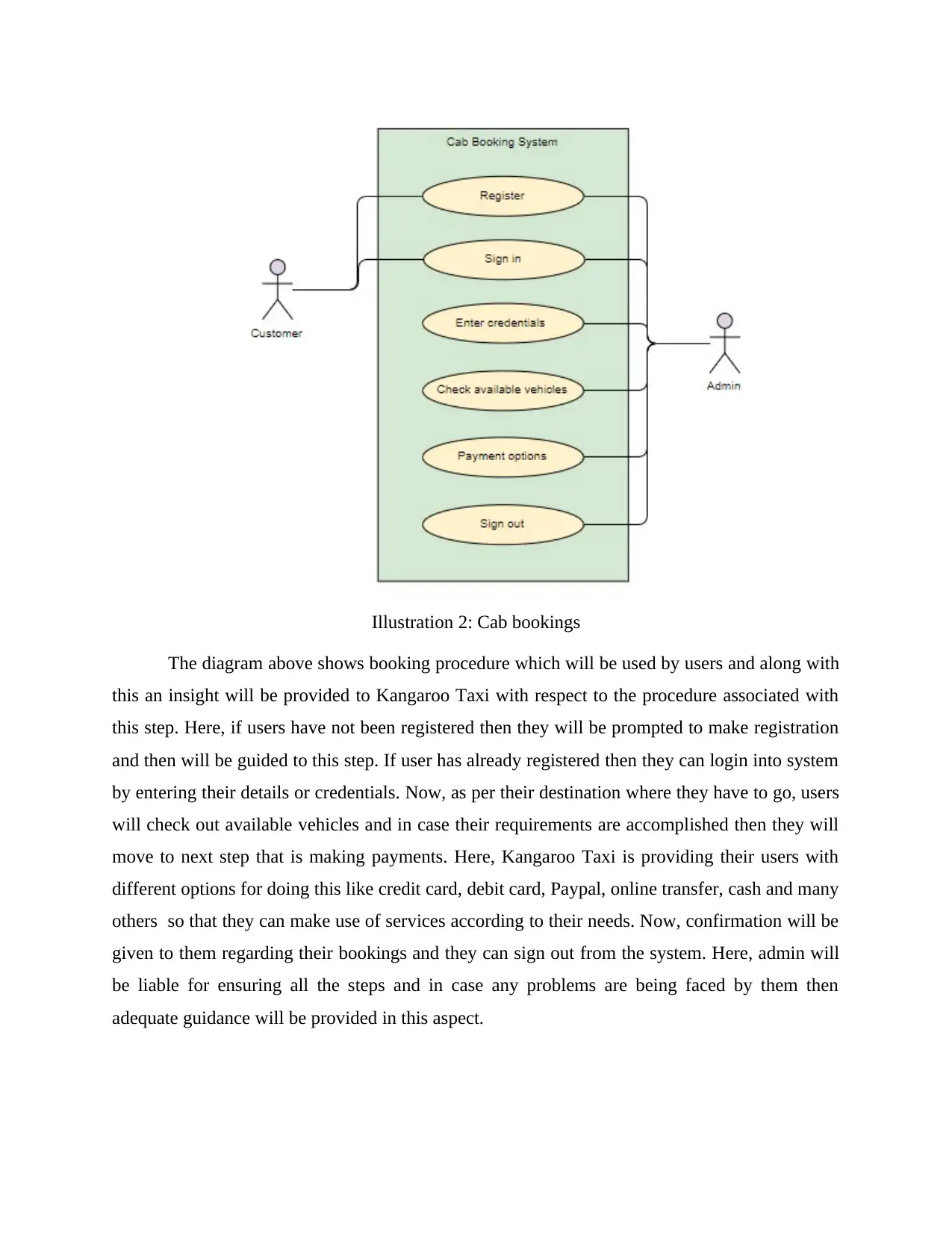
Illustration 2: Cab bookings
The diagram above shows booking procedure which will be used by users and along with
this an insight will be provided to Kangaroo Taxi with respect to the procedure associated with
this step. Here, if users have not been registered then they will be prompted to make registration
and then will be guided to this step. If user has already registered then they can login into system
by entering their details or credentials. Now, as per their destination where they have to go, users
will check out available vehicles and in case their requirements are accomplished then they will
move to next step that is making payments. Here, Kangaroo Taxi is providing their users with
different options for doing this like credit card, debit card, Paypal, online transfer, cash and many
others so that they can make use of services according to their needs. Now, confirmation will be
given to them regarding their bookings and they can sign out from the system. Here, admin will
be liable for ensuring all the steps and in case any problems are being faced by them then
adequate guidance will be provided in this aspect.
Use Case diagram
The diagrams which are liable for summarising relationship between use cases, sytems and
actors are defined as use case. But they do not illustrate order in which things will be carried out
for attainment of gaols related with each diagram (Fadillah and Fitriana, 2019). It denotes simple
illustration in context of communication that occurs between system and its users.
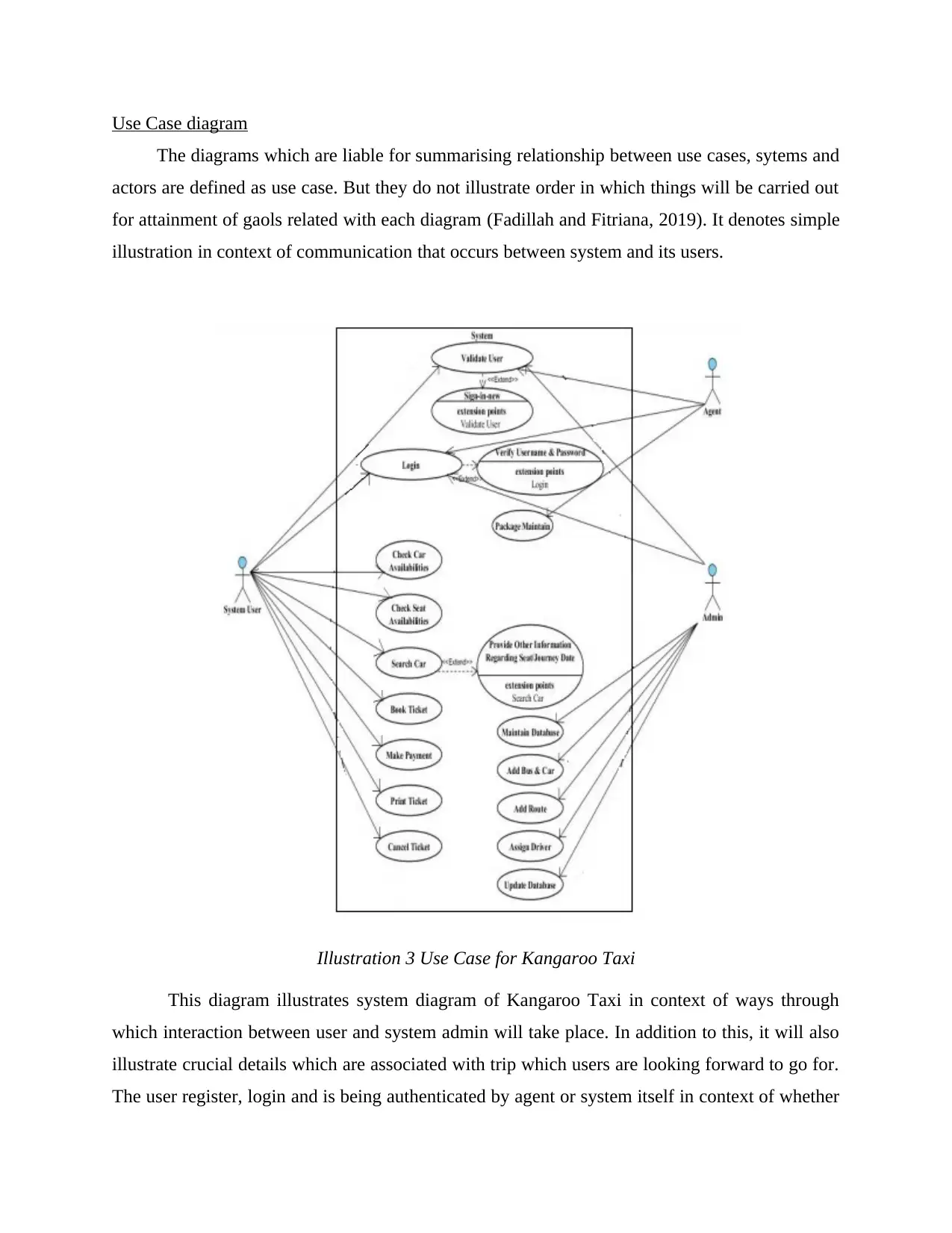
Illustration 3 Use Case for Kangaroo Taxi
This diagram illustrates system diagram of Kangaroo Taxi in context of ways through
which interaction between user and system admin will take place. In addition to this, it will also
illustrate crucial details which are associated with trip which users are looking forward to go for.
The user register, login and is being authenticated by agent or system itself in context of whether
The diagrams which are liable for summarising relationship between use cases, sytems and
actors are defined as use case. But they do not illustrate order in which things will be carried out
for attainment of gaols related with each diagram (Fadillah and Fitriana, 2019). It denotes simple
illustration in context of communication that occurs between system and its users.
Illustration 3 Use Case for Kangaroo Taxi
This diagram illustrates system diagram of Kangaroo Taxi in context of ways through
which interaction between user and system admin will take place. In addition to this, it will also
illustrate crucial details which are associated with trip which users are looking forward to go for.
The user register, login and is being authenticated by agent or system itself in context of whether
⊘ This is a preview!⊘
Do you want full access?
Subscribe today to unlock all pages.
Trusted by 1+ million students worldwide
details entered by them are adequate or not. Furthermore, in case credentials are not appropriate
then error message will appear and they will not be granted access into the system. The diagram
illustrates actors like user; admin and agent are being connected for granting adequate
information to users related with search cab, making payments, etc. Here, actors have to carry
out different roles and use cases are extended such as login is being extended for validating
username as well as password so that only verified user can have access to system. Moreover,
now user will look for availability of cars according to their needs and in case if they are sharing
cab then they can also have details about how many people but not more than this. In case there,
needs are not accomplished then they can check availability of other cab or Taxi.
Users can further make bookings; carry out payments as per their feasibility as well as
have a confirmation for the same. In addition to this, they also have option for cancelling their
bookings. Here, actor agent is responsible to validate users and keep package details as per trip
or number of bookings which are being made by their customers. Authentication or validation is
done to ensure that it is not a machine and user sitting other side is human. It is necessary as it
will allow them to have adequate customers. Admin have different liabilities like entering
vehicles, their details, and drivers, assigning location and deleting or modifying them as per
availability. This illustrates the entire working use case for Kangaroo Taxi and will furnish ease
within processes conducted by them.
Entity relationship diagram
The data modelling technique which is liable for illustrating graphical information
associated with system and relationship which prevails among different entities is defined as
entity relationship diagram (Genta and Morello, 2019). This denotes conceptual and
representational model of information that is being used for representing framework
infrastructure of entities. The primary elements within this framework are entities like car,
relationship such as user or customer with admin and attributes like id, name, contact number
etc. (they are liable for uniquely identifying their users.
Paraphrase This Document
Need a fresh take? Get an instant paraphrase of this document with our AI Paraphraser
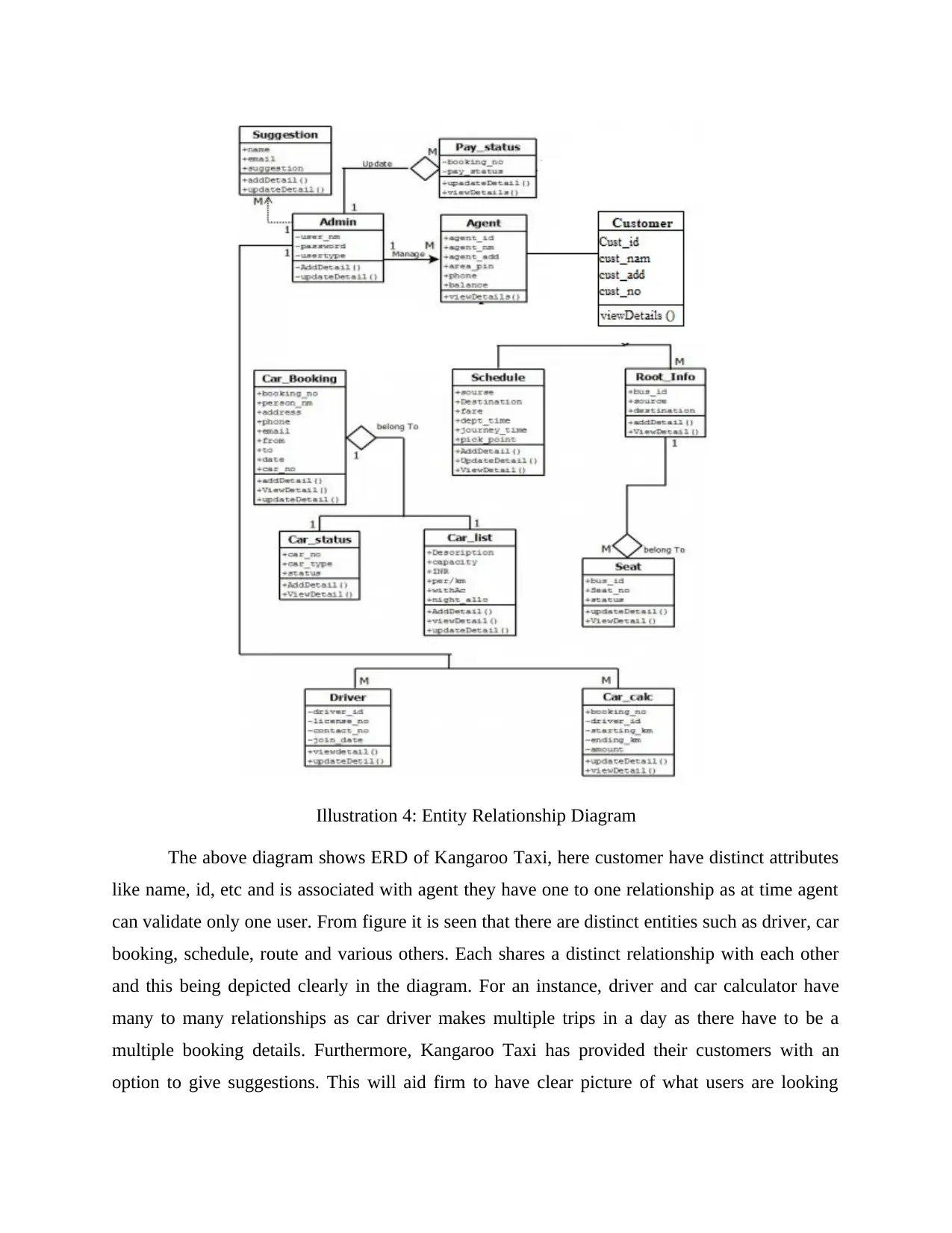
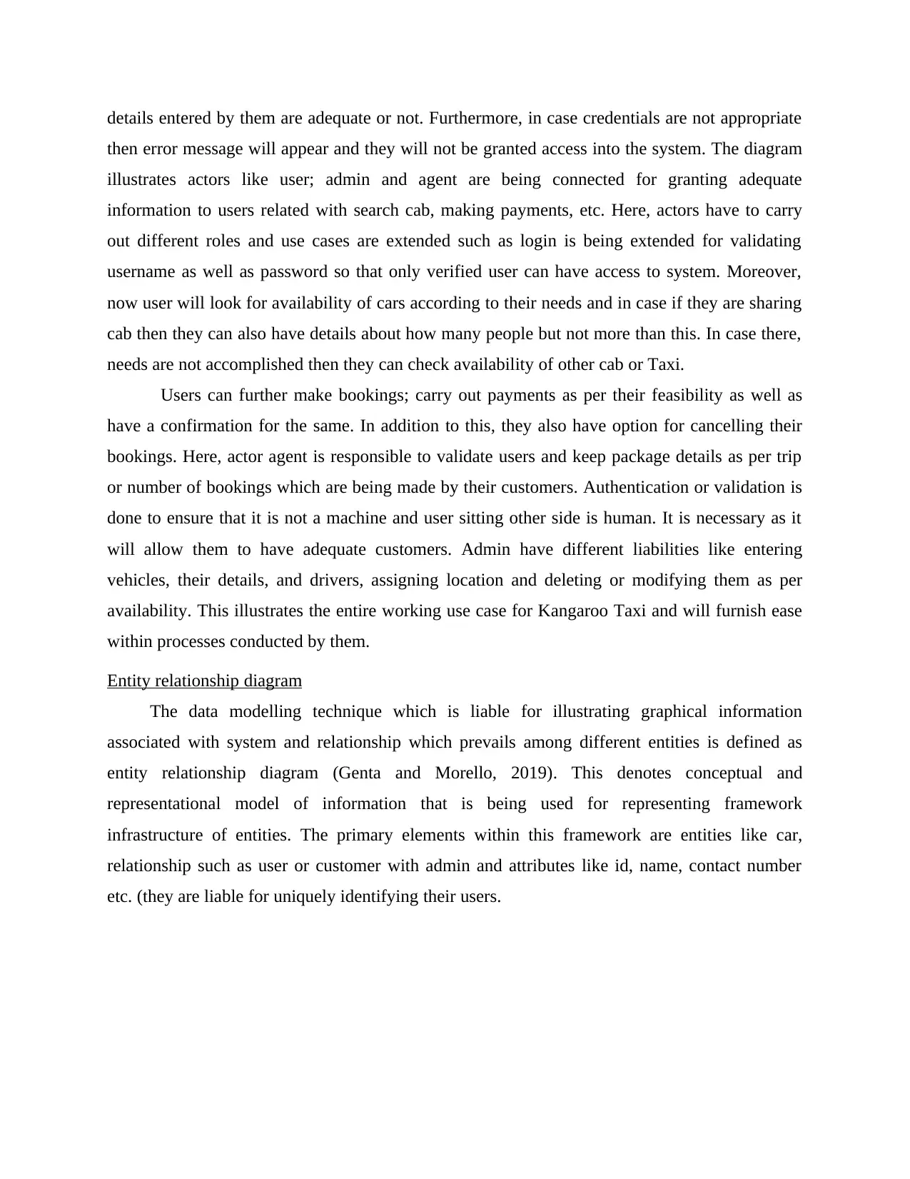
Illustration 4: Entity Relationship Diagram
The above diagram shows ERD of Kangaroo Taxi, here customer have distinct attributes
like name, id, etc and is associated with agent they have one to one relationship as at time agent
can validate only one user. From figure it is seen that there are distinct entities such as driver, car
booking, schedule, route and various others. Each shares a distinct relationship with each other
and this being depicted clearly in the diagram. For an instance, driver and car calculator have
many to many relationships as car driver makes multiple trips in a day as there have to be a
multiple booking details. Furthermore, Kangaroo Taxi has provided their customers with an
option to give suggestions. This will aid firm to have clear picture of what users are looking
forward for more in their services and this will lead them to amplify their overall services via
new information system.
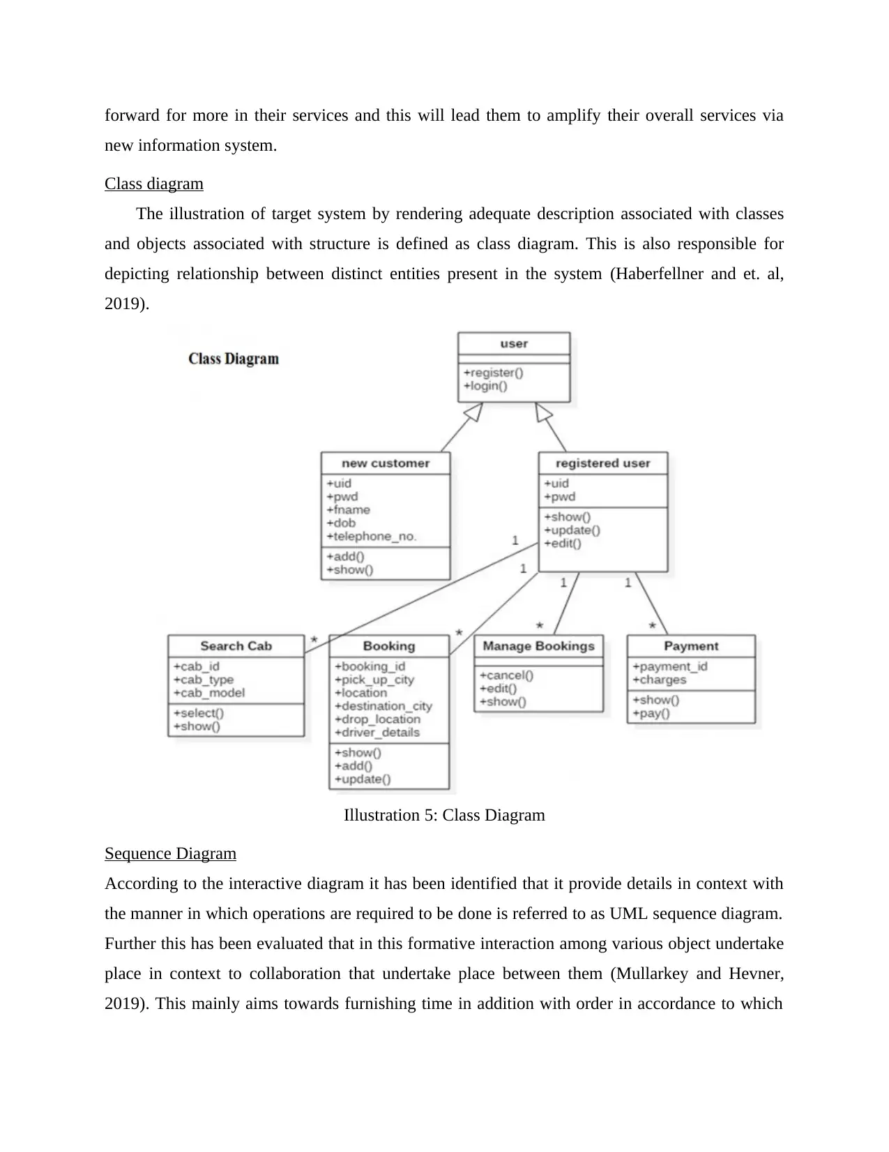
Class diagram
The illustration of target system by rendering adequate description associated with classes
and objects associated with structure is defined as class diagram. This is also responsible for
depicting relationship between distinct entities present in the system (Haberfellner and et. al,
2019).
Illustration 5: Class Diagram
Sequence Diagram
According to the interactive diagram it has been identified that it provide details in context with
the manner in which operations are required to be done is referred to as UML sequence diagram.
Further this has been evaluated that in this formative interaction among various object undertake
place in context to collaboration that undertake place between them (Mullarkey and Hevner,
2019). This mainly aims towards furnishing time in addition with order in accordance to which
new information system.
Class diagram
The illustration of target system by rendering adequate description associated with classes
and objects associated with structure is defined as class diagram. This is also responsible for
depicting relationship between distinct entities present in the system (Haberfellner and et. al,
2019).
Illustration 5: Class Diagram
Sequence Diagram
According to the interactive diagram it has been identified that it provide details in context with
the manner in which operations are required to be done is referred to as UML sequence diagram.
Further this has been evaluated that in this formative interaction among various object undertake
place in context to collaboration that undertake place between them (Mullarkey and Hevner,
2019). This mainly aims towards furnishing time in addition with order in accordance to which
⊘ This is a preview!⊘
Do you want full access?
Subscribe today to unlock all pages.
Trusted by 1+ million students worldwide
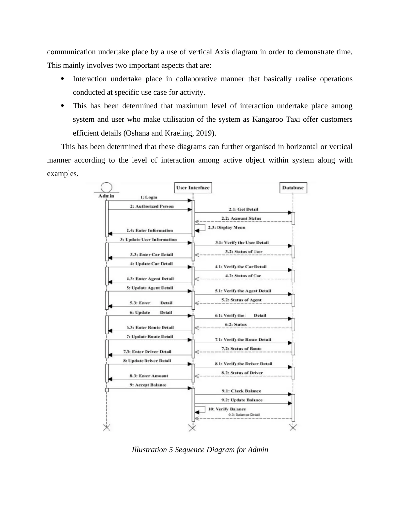
communication undertake place by a use of vertical Axis diagram in order to demonstrate time.
This mainly involves two important aspects that are:
Interaction undertake place in collaborative manner that basically realise operations
conducted at specific use case for activity.
This has been determined that maximum level of interaction undertake place among
system and user who make utilisation of the system as Kangaroo Taxi offer customers
efficient details (Oshana and Kraeling, 2019).
This has been determined that these diagrams can further organised in horizontal or vertical
manner according to the level of interaction among active object within system along with
examples.
Illustration 5 Sequence Diagram for Admin
Paraphrase This Document
Need a fresh take? Get an instant paraphrase of this document with our AI Paraphraser
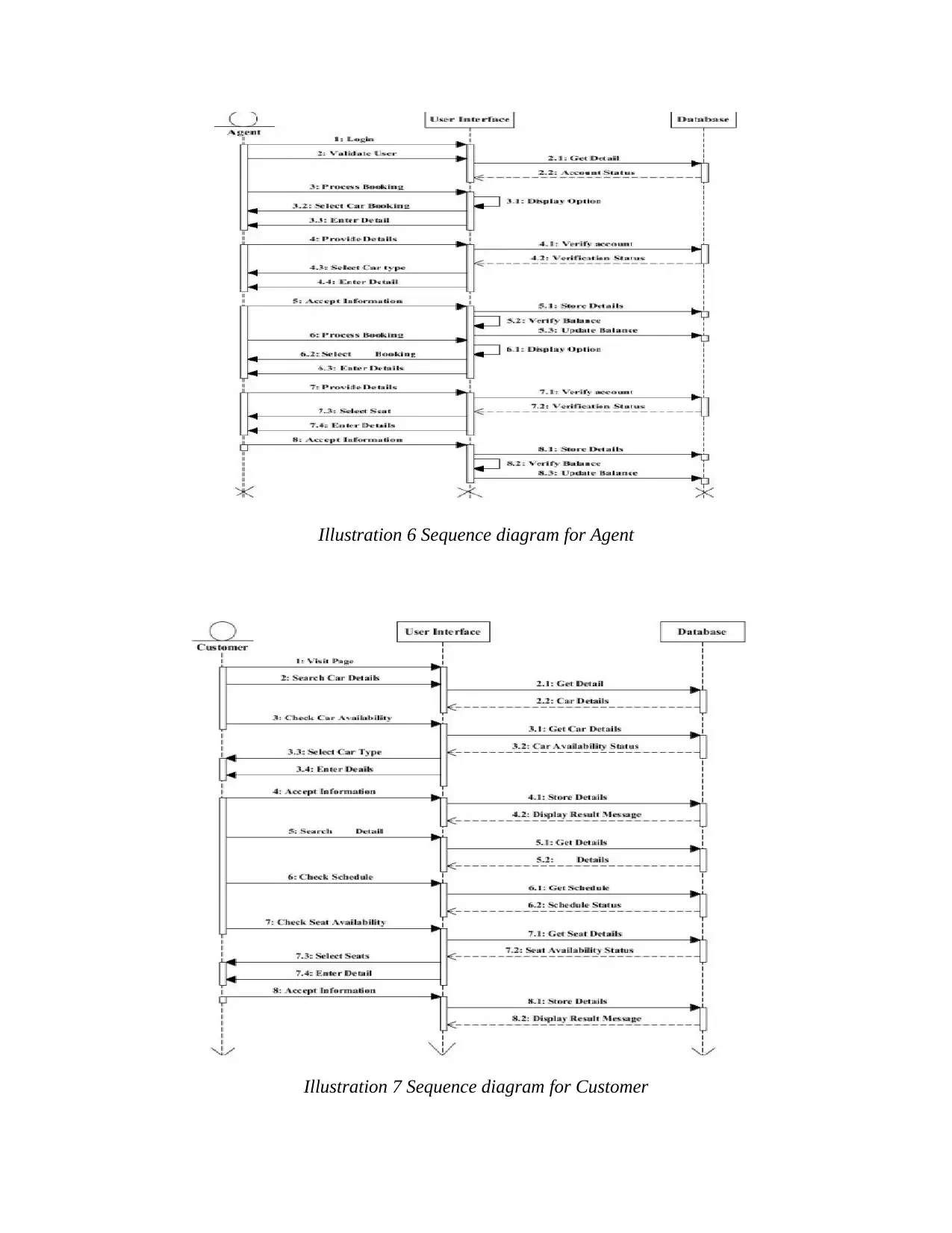
Illustration 6 Sequence diagram for Agent
Illustration 7 Sequence diagram for Customer
Illustration 7 Sequence diagram for Customer
This has been evaluated that diagram effectively demonstrate sequence diagram for
different admin, use cases and agent in addition with consumers. Further this has been evaluated
that horizontal Axis demonstrates factors that are required to be undertaken in order to conduct
communication. Along with this it has been demonstrated that operation that are given from right
to left defects sequence of message. Vertical axis implies proceedings down page or time
progressing. The arrow among user interface as well as admin illustrates message that represents
lifelines for interaction as well as invocation of target lifelines. Along with this, a thing form of
rectangle that is demonstrated below admin along with other use cases identifies period with the
help of which operations are required to be undertaken, they are further get aligned from stating
till end.
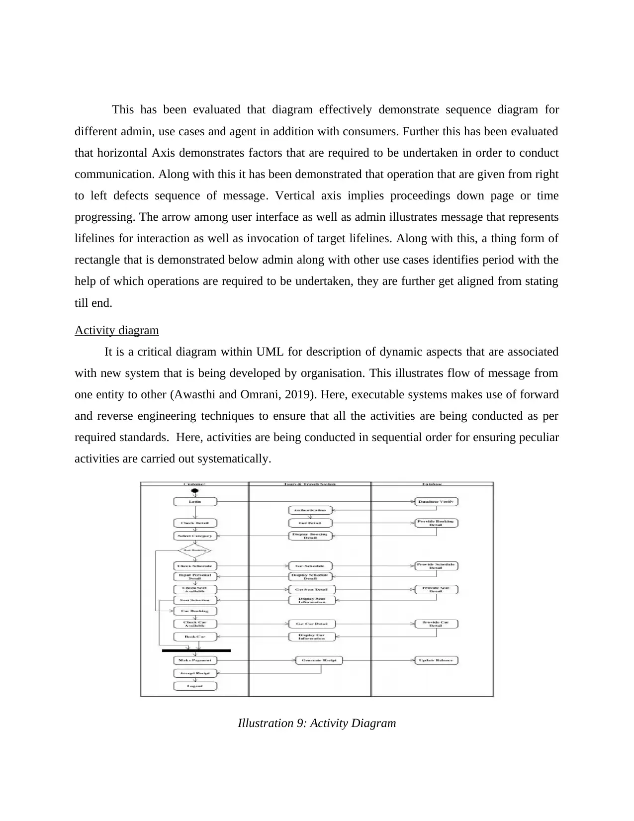
Activity diagram
It is a critical diagram within UML for description of dynamic aspects that are associated
with new system that is being developed by organisation. This illustrates flow of message from
one entity to other (Awasthi and Omrani, 2019). Here, executable systems makes use of forward
and reverse engineering techniques to ensure that all the activities are being conducted as per
required standards. Here, activities are being conducted in sequential order for ensuring peculiar
activities are carried out systematically.
Illustration 9: Activity Diagram
different admin, use cases and agent in addition with consumers. Further this has been evaluated
that horizontal Axis demonstrates factors that are required to be undertaken in order to conduct
communication. Along with this it has been demonstrated that operation that are given from right
to left defects sequence of message. Vertical axis implies proceedings down page or time
progressing. The arrow among user interface as well as admin illustrates message that represents
lifelines for interaction as well as invocation of target lifelines. Along with this, a thing form of
rectangle that is demonstrated below admin along with other use cases identifies period with the
help of which operations are required to be undertaken, they are further get aligned from stating
till end.
Activity diagram
It is a critical diagram within UML for description of dynamic aspects that are associated
with new system that is being developed by organisation. This illustrates flow of message from
one entity to other (Awasthi and Omrani, 2019). Here, executable systems makes use of forward
and reverse engineering techniques to ensure that all the activities are being conducted as per
required standards. Here, activities are being conducted in sequential order for ensuring peculiar
activities are carried out systematically.
Illustration 9: Activity Diagram
⊘ This is a preview!⊘
Do you want full access?
Subscribe today to unlock all pages.
Trusted by 1+ million students worldwide
1 out of 14
Related Documents


Your All-in-One AI-Powered Toolkit for Academic Success.
+13062052269
info@desklib.com
Available 24*7 on WhatsApp / Email
![[object Object]](/_next/static/media/star-bottom.7253800d.svg)
Unlock your academic potential
Copyright © 2020–2026 A2Z Services. All Rights Reserved. Developed and managed by ZUCOL.