KCL: Resistors in Series, Parallel and Capacitor Experiment

Verified

Added on  2022/03/09

|14
|1598
|29
Practical Assignment
AI Summary
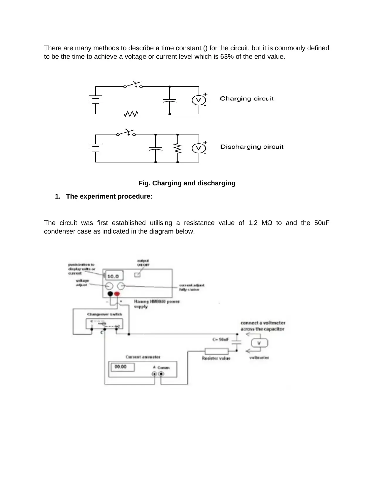
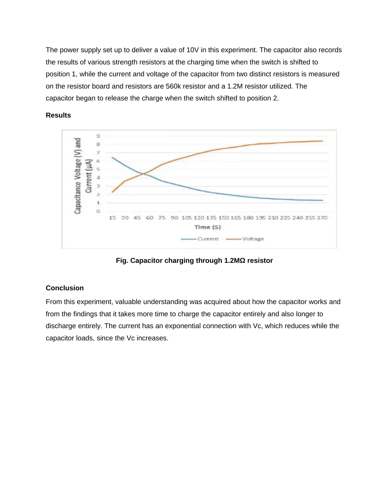
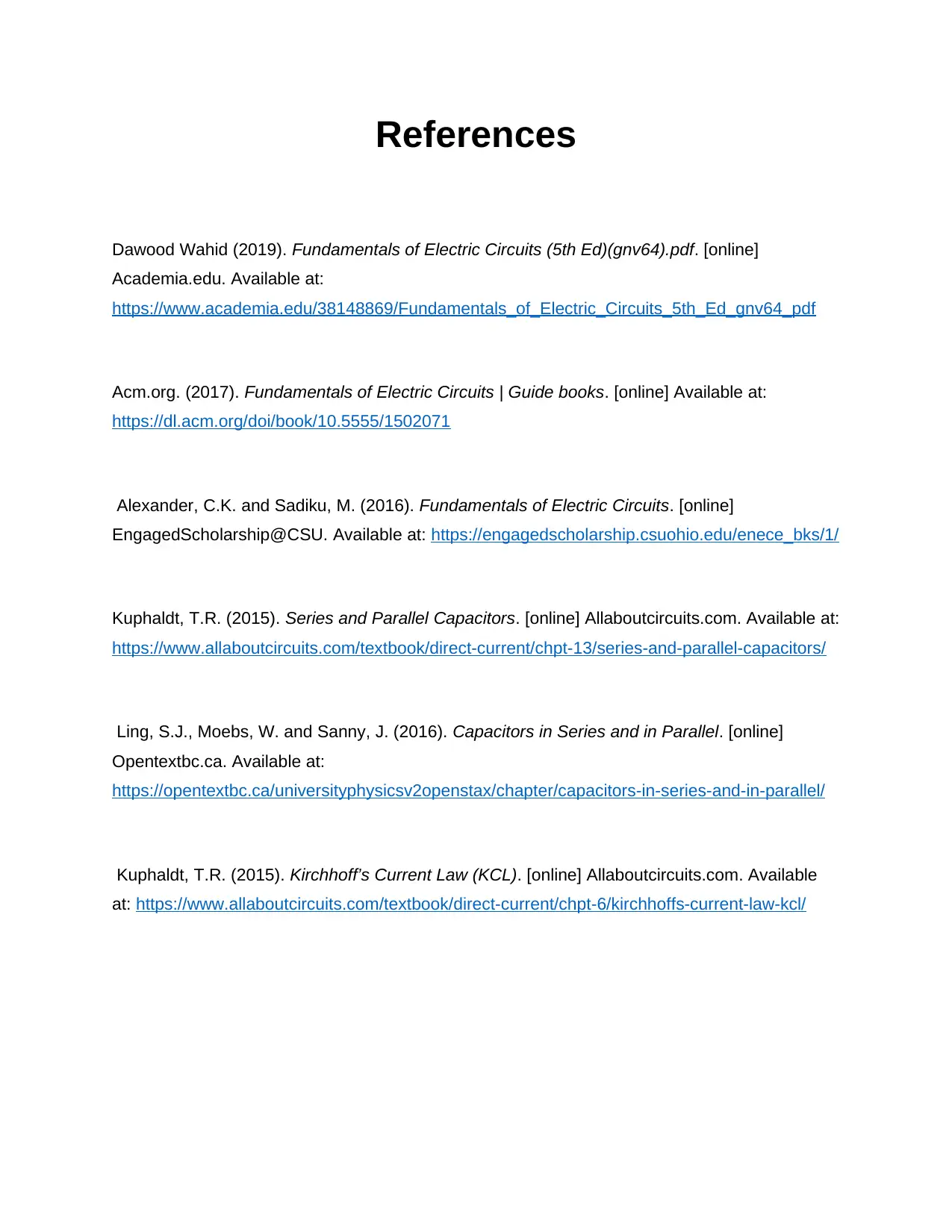
This practical assignment presents a comprehensive exploration of Kirchhoff's Laws (KCL) through experiments involving resistors and capacitors. The experiments include analyzing resistors in series and parallel configurations, and investigating the charging and discharging behavior of capacitors. The assignment details the procedures, equipment used (including multimeters and power supplies), and the observations made during the experiments. The analysis and discussion sections delve into the application of KCL, Ohm's Law, and the time constant concept for capacitors, comparing experimental results with theoretical expectations. The conclusion summarizes the key findings, such as the voltage drops in series circuits, current division in parallel circuits, and the exponential nature of capacitor charging and discharging. The document also includes references to relevant sources that support the concepts and experimental procedures.
tabler-icon-diamond-filled.svg

Contribute Materials

Your contribution can guide someone’s learning journey. Share your documents today.
Document Page
KCL: Resistors in series
and
Charging and discharging a Capacitor
tabler-icon-diamond-filled.svg

Secure Best Marks with AI Grader

Need help grading? Try our AI Grader for instant feedback on your assignments.
Document Page
Experiment No. 3
KCL: Resistors in series
Introduction:
KVL of Kirchhoff indicates that sum voltages are equivalent to any drop in voltage in the same
loop in a closed loop network. The premise behind the KVL is that no energy loss or generated
by the electric loop must amount to the sum of load voltages in a circuit in the sense that the net
voltage increases the voltage source (Rizzoni, 2009). The Kirchhoff Voltage Law clearly states
that the algebraic voltage around a circuit is always equal to zero. This experiment also
concentrates on the rule now applicable in Kirchhoff, which states that a circuit, with an
algebraic current level at zero, flows into each junction or node in a circuit.
Experiment
1. The Kirchhoff Voltage Law says that each closed branch of loop algebraic voltage is 0.
2. Kirchhoff's current law says that the current entry is equal to the current that leaves that node
within an electrical circuit in any node.
:
Document Page
OBJECTIVES:
The aim of this experiment was to illustrate the overall voltage drops in each resistor (potential
differences) inside a series circuit equal to the voltage that is provided throughout the circuit.
This Experiment focused mostly on the voltage and resistor of Kirchhoff law. It's in the current
Kirchhoff Law or KCL that stipulates that 'the total current or charge entering a crossroads or
knots is exactly the same as the load leaving the node, since it can only go away. In Part C, it is
necessary to know the purpose of series and parallel circuits.
Equipment Required:
1 DC voltmeter
15 Ω, 22 Ω, 33 Ω resistors
1 Hameg Power Supply.
1 DC multimeter.
Procedure
First of all, a DC voltmeter was used, the V-button was pressed on, and the plug was connected
to the common (COM) and V-sockets. Connect the power supply and resistors in series, as
shown in the figure below:
Document Page
When the circuit was linked, the power switched on. To set the voltage to 5 use the voltage
adjustment key Second, every voltage (R1, R2 and R3), i.e. V1, V2, & V3, recorded by each
resistor (known as resistor voltage drop).
tabler-icon-diamond-filled.svg

Secure Best Marks with AI Grader

Need help grading? Try our AI Grader for instant feedback on your assignments.
Document Page
DC voltage 6.00 V 11.00 V
Ammeter current 71.0MA 139.0MA
Voltage {V1 , V2 , V3}
V1(R1) 1.07 V 2.13 V
V2(R2) 1.57 V 3.1V
V3(R3) 2.36 V 4.7 V
Current through resistors
I1 0.074A 0.144A
I2 0.072A 0.139A
I3 0.072A 0.140A
Power dissipated by resistors
P1 0.079W 0.4W
P2 0.111W 0.41W
ssP3 0.165W 0.68W
Fig. Resistors in series
Analysis and discussion:
The experiment focused on series circuits. To understand and apply, knowledge of the Kirchhoff
rules was necessary. All value of 5V and the total value of 5V of V1+V2+V 4,90V and the total
value of 9,61V for 10V were considerably different. The value of V was 4.90 V. Two or more
reasons might change the overall potential differences in this circuit, one of which may be a
resistor failure, since the other may be due to an error-calibration multimeter not exactly the
value it asserts.
Conclusion:
The faces of each one that is learned across the whole series are the same, but the current is
split throughout each branch. The current is same all around the place. On the other hand, the
current in the parallel circuit divides in each branch of the circuit while the voltage stays the
same on all branches. The provider may also vary from the calculation of error percentage.
Document Page
Resistors in parallel
Introduction:
In present Kirchhoff or KCL laws, 'Vt or load entry or node' is simply the same as the charge that
leaves the node, since the node is just an escape route.
Equipment:
The devices used were as follows: Direct Current (in DC current mode, the multimeter was
used). There are two resistors of 22 ohm and 33 ohm. One power supply unit Hameg HM8040
5V.
Procedure:
The 22 ohm and 33 ohm resistors were coupled with two DC-Ammeters and a voltage source,
along with the following circuit diagram
Figure. Diagram illustrating the resistors in parallel
Figure. Demonstrating the real circuit.
Switch on the power supply and turn the current adjustment handle clockwise once the circuit is
connected as above. The voltage adjusted for the power output is therefore 5 V.
The Centre grey OUTPUT on/off from the power supply also activated the output. The current
read (I1 and I2) current supplier of the power system (Vs) as described in the table above are
acquired using an ammeter to pass through the circuit resistors and recorded in the table below.
Document Page
I1 through 22 Ω , (I1) 216.8mA
I2 through 33 Ω (I2) 150.2mA
(I1+I2) 365mA
(Vs) 5V
Formula: R1 = Vs/I1 24.17 Ω
Formula : R2 = Vs/I2 34.71 Ω
Formula: Rt = Vs/Is 13.76
Figure. Resistors in parallel
Analysis and discussion:
Rt circuit with current and voltage has been preserved along with Ohm's law. Rt was also
calculated, yielding a 13.74 ohm value. The findings were determined by using the following
formula:
OHM’S LAW:
But when the Ohms law applied it resulted in 13.20 amounts. But if the following formula
applied, the value of the current was the value of the supply current, according to the Table, the
supply current was divided among each resistor. 364Ma (It=Vs/Rs) equal.
Conclusion
tabler-icon-diamond-filled.svg

Paraphrase This Document

Need a fresh take? Get an instant paraphrase of this document with our AI Paraphraser
Document Page
The current is projected to be modest in comparison to the smaller by a larger –33 ohms –22
ohms is bigger as less current passes through a high resistance. Again, the values are not
reliable, since errors or resistors cannot be loaded with the measurement equipment.
Experiment No. 4
Charging and discharging a Capacitor
Introduction:
The Capacitors are generally power and electric charging devices. There are many useful
applications, such as in DC power supply filters and pulse lasers as energy storage banks.
Manly AC current is used by the capacitors. Two conducting surfaces consist of capacitors that
are separated by an isolating layer termed a dielectric layer.
Equipment needed
50μF Capacitor box.
1 changeover switch 1 resistance board
1 timer
1 Hameg power supply.
2 digital multimeter.
Procedure:
1. Theory:
When an R-C circuit is linked with a power source, the voltage across the capacitor continuously
changes as seen in Figure below. The voltage is constantly fluctuating.
Document Page
There are many methods to describe a time constant (̈) for the circuit, but it is commonly defined
to be the time to achieve a voltage or current level which is 63% of the end value.
Fig. Charging and discharging
1. The experiment procedure:
The circuit was first established utilising a resistance value of 1.2 MΩ to and the 50uF
condenser case as indicated in the diagram below.
Document Page
The power supply set up to deliver a value of 10V in this experiment. The capacitor also records
the results of various strength resistors at the charging time when the switch is shifted to
position 1, while the current and voltage of the capacitor from two distinct resistors is measured
on the resistor board and resistors are 560k resistor and a 1.2M resistor utilized. The
capacitor began to release the charge when the switch shifted to position 2.
Results
Fig. Capacitor charging through 1.2MΩ resistor
Conclusion
From this experiment, valuable understanding was acquired about how the capacitor works and
from the findings that it takes more time to charge the capacitor entirely and also longer to
discharge entirely. The current has an exponential connection with Vc, which reduces while the
capacitor loads, since the Vc increases.
tabler-icon-diamond-filled.svg

Secure Best Marks with AI Grader

Need help grading? Try our AI Grader for instant feedback on your assignments.
Document Page
References
Dawood Wahid (2019). Fundamentals of Electric Circuits (5th Ed)(gnv64).pdf. [online]
Academia.edu. Available at:
https://www.academia.edu/38148869/Fundamentals_of_Electric_Circuits_5th_Ed_gnv64_pdf
Acm.org. (2017). Fundamentals of Electric Circuits | Guide books. [online] Available at:
https://dl.acm.org/doi/book/10.5555/1502071
Alexander, C.K. and Sadiku, M. (2016). Fundamentals of Electric Circuits. [online]
EngagedScholarship@CSU. Available at: https://engagedscholarship.csuohio.edu/enece_bks/1/
Kuphaldt, T.R. (2015). Series and Parallel Capacitors. [online] Allaboutcircuits.com. Available at:
https://www.allaboutcircuits.com/textbook/direct-current/chpt-13/series-and-parallel-capacitors/
Ling, S.J., Moebs, W. and Sanny, J. (2016). Capacitors in Series and in Parallel. [online]
Opentextbc.ca. Available at:
https://opentextbc.ca/universityphysicsv2openstax/chapter/capacitors-in-series-and-in-parallel/
Kuphaldt, T.R. (2015). Kirchhoff’s Current Law (KCL). [online] Allaboutcircuits.com. Available
at: https://www.allaboutcircuits.com/textbook/direct-current/chpt-6/kirchhoffs-current-law-kcl/
Document Page
Appendices
Document Page
tabler-icon-diamond-filled.svg

Paraphrase This Document

Need a fresh take? Get an instant paraphrase of this document with our AI Paraphraser
Document Page
chevron_up_icon
1 out of 14
circle_padding
hide_on_mobile
zoom_out_icon
logo.png

Your All-in-One AI-Powered Toolkit for Academic Success.

Available 24*7 on WhatsApp / Email

[object Object]