Local Area Network: Design, Implementation, Security, and Management
VerifiedAdded on 2024/05/17
|47
|6713
|211
Report
AI Summary
This report provides a comprehensive overview of Local Area Network (LAN) technologies, covering design, implementation, and management aspects. It begins with an evaluation of different LAN technologies, including wired and wireless LANs, IEEE 802.11, and IEEE 802.3 Ethernet, and delves into VLANs and their benefits. The report critically analyzes traffic-intensive services like Video-over-IP and Voice-on-Demand, examining their performance and impact on network efficiency. A significant portion is dedicated to designing a LAN infrastructure for FootFall Marketing Field, including network topology, addressing schemes, and component suitability. The implementation phase covers building and configuring the LAN, implementing network security measures, and conducting thorough testing. Finally, the report addresses LAN management, monitoring, troubleshooting, and performance evaluation, providing a holistic view of LAN operations. This assignment solution is available on Desklib, a platform offering a wide range of study resources for students.
Local Area Network (LAN)
Paraphrase This Document
Need a fresh take? Get an instant paraphrase of this document with our AI Paraphraser
Table of Contents
Introduction.....................................................................................................................................4
LO1 Understand the impact of LAN technologies...........................................................................5
A.C 1.1 critically evaluate different LAN technologies................................................................5
A.C 1.2 Critically analyze traffic intensive services and their performance..............................15
A.C 1.3 Discuss LAN concerns and make recommendations to sustain network security,
reliability, and performance......................................................................................................18
LO2 - Be able to design LAN infrastructures..................................................................................20
A.C 2.1 Design a LAN infrastructure to meet a given requirement.....................................20
A.C 2.2 critically evaluate the suitability of LAN components...................................................23
LO3- Be able to implement LAN infrastructures...........................................................................24
A.C 3.1 Build and configure a LAN (including services) to meet a given requirement..............24
A.C 3.2 Implement network security on a LAN.........................................................................32
A.C 3.3 critically review and test a LAN.....................................................................................36
LO4- Be able to manage LAN infrastructures................................................................................39
AC 4.1 Monitor and troubleshoot a LAN................................................................................39
AC 4.2 Resolve LAN issues to improve security, reliability, and performance.......................40
AC 4.3 Critically evaluate the performance of a LAN.............................................................41
Conclusion:....................................................................................................................................42
References.....................................................................................................................................43
1
List of Figures:
Figure 1 Wire LAN network.............................................................................................................6
Figure 2 Wireless LAN network.......................................................................................................6
Figure 3 Ethernet cable to connect the device................................................................................7
Figure 4 Token ring to connect the system.....................................................................................8
Figure 5 VLAN network....................................................................................................................9
Figure 6 Hub...................................................................................................................................10
Figure 7 Router..............................................................................................................................11
Figure 8 Switches...........................................................................................................................11
Figure 9 Repeaters.........................................................................................................................12
Figure 10 Bridges...........................................................................................................................12
Figure 11 UTP (unshielded twisted pair).......................................................................................13
Figure 12 Coaxial cable..................................................................................................................13
Figure 13 STP(shielded twisted pair).............................................................................................14
Figure 14 Optic fiber table.............................................................................................................14
Figure 15 Working of VoI...............................................................................................................15
Figure 16 Video-on-demand..........................................................................................................16
Figure 17 Video and audio streaming............................................................................................16
Figure 18 Network Design View of the Organization....................................................................20
Figure 19 Star topologies...............................................................................................................21
Figure 20Configuration..................................................................................................................25
Figure 21 Router configuration......................................................................................................27
Figure 22 Configuration of installed router...................................................................................29
Figure 23 HTTP and DNS service of the network...........................................................................30
Figure 24 DHCP Server...................................................................................................................30
Figure 25 Design view of Network of Cisco Packet Tracer............................................................31
Figure 26 Configuration.................................................................................................................34
Figure 27 Test Case 1.....................................................................................................................37
Figure 28 Test Case 2.....................................................................................................................37
2
⊘ This is a preview!⊘
Do you want full access?
Subscribe today to unlock all pages.
Trusted by 1+ million students worldwide
Figure 29: Test Scenario three.......................................................................................................38
List of Figures:
Table 1 Comparison between Wireless and Wired LAN..................................................................5
Table 2 Comparison of IEEE 802.11 and IEEE 802.3........................................................................8
Table 3 IP Precedence Table..........................................................................................................17
Table4 Test Case Table..................................................................................................................36
3
Paraphrase This Document
Need a fresh take? Get an instant paraphrase of this document with our AI Paraphraser
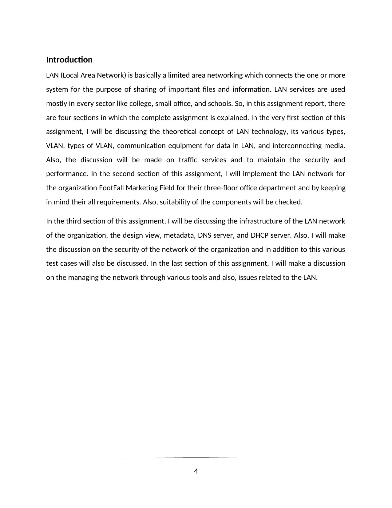
Introduction
LAN (Local Area Network) is basically a limited area networking which connects the one or more
system for the purpose of sharing of important files and information. LAN services are used
mostly in every sector like college, small office, and schools. So, in this assignment report, there
are four sections in which the complete assignment is explained. In the very first section of this
assignment, I will be discussing the theoretical concept of LAN technology, its various types,
VLAN, types of VLAN, communication equipment for data in LAN, and interconnecting media.
Also, the discussion will be made on traffic services and to maintain the security and
performance. In the second section of this assignment, I will implement the LAN network for
the organization FootFall Marketing Field for their three-floor office department and by keeping
in mind their all requirements. Also, suitability of the components will be checked.
In the third section of this assignment, I will be discussing the infrastructure of the LAN network
of the organization, the design view, metadata, DNS server, and DHCP server. Also, I will make
the discussion on the security of the network of the organization and in addition to this various
test cases will also be discussed. In the last section of this assignment, I will make a discussion
on the managing the network through various tools and also, issues related to the LAN.
4
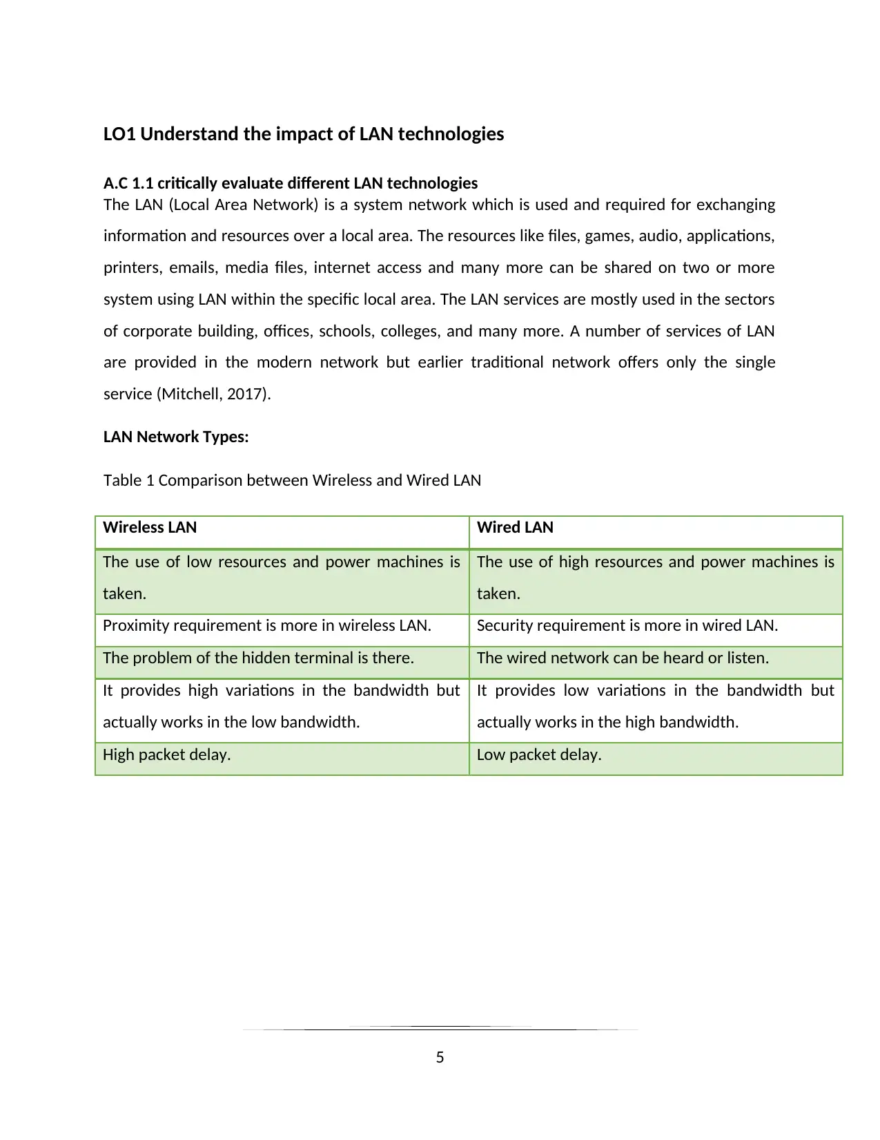
LO1 Understand the impact of LAN technologies
A.C 1.1 critically evaluate different LAN technologies
The LAN (Local Area Network) is a system network which is used and required for exchanging
information and resources over a local area. The resources like files, games, audio, applications,
printers, emails, media files, internet access and many more can be shared on two or more
system using LAN within the specific local area. The LAN services are mostly used in the sectors
of corporate building, offices, schools, colleges, and many more. A number of services of LAN
are provided in the modern network but earlier traditional network offers only the single
service (Mitchell, 2017).
LAN Network Types:
Table 1 Comparison between Wireless and Wired LAN
Wireless LAN Wired LAN
The use of low resources and power machines is
taken.
The use of high resources and power machines is
taken.
Proximity requirement is more in wireless LAN. Security requirement is more in wired LAN.
The problem of the hidden terminal is there. The wired network can be heard or listen.
It provides high variations in the bandwidth but
actually works in the low bandwidth.
It provides low variations in the bandwidth but
actually works in the high bandwidth.
High packet delay. Low packet delay.
5
⊘ This is a preview!⊘
Do you want full access?
Subscribe today to unlock all pages.
Trusted by 1+ million students worldwide
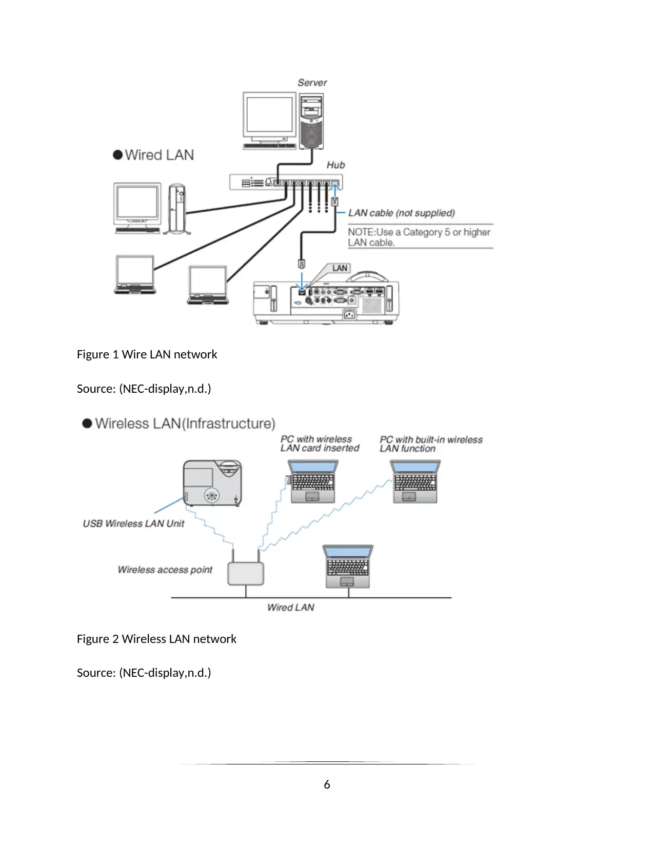
Figure 1 Wire LAN network
Source: (NEC-display,n.d.)
Figure 2 Wireless LAN network
Source: (NEC-display,n.d.)
6
Source: (NEC-display,n.d.)
Figure 2 Wireless LAN network
Source: (NEC-display,n.d.)
6
Paraphrase This Document
Need a fresh take? Get an instant paraphrase of this document with our AI Paraphraser
IEEE 802.11 Wi-Fi
This IEEE 802.11 is basically a standard for wireless networking system. It generally works on
the security of wireless networking, Access Control of Media, and QoS (Quality of Service)
(Hope, 2017).
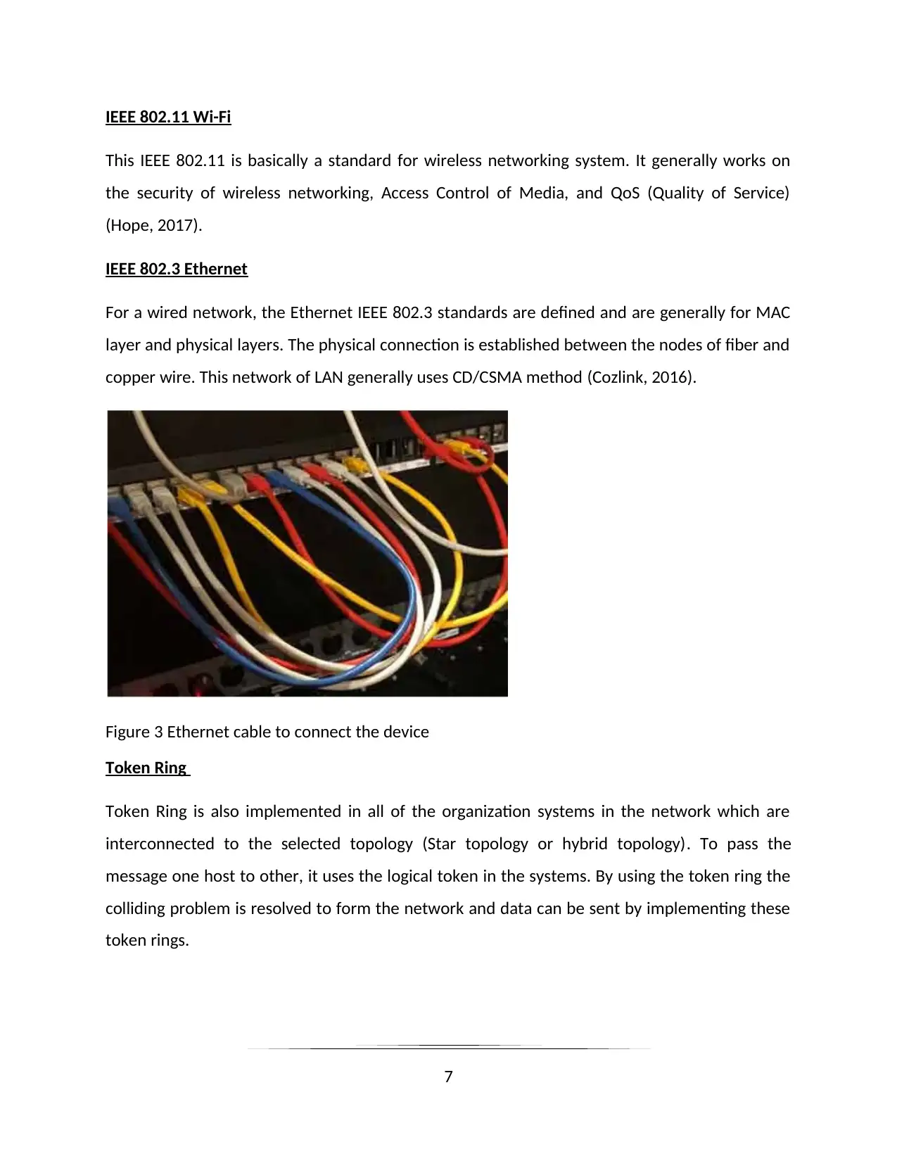
IEEE 802.3 Ethernet
For a wired network, the Ethernet IEEE 802.3 standards are defined and are generally for MAC
layer and physical layers. The physical connection is established between the nodes of fiber and
copper wire. This network of LAN generally uses CD/CSMA method (Cozlink, 2016).
Figure 3 Ethernet cable to connect the device
Token Ring
Token Ring is also implemented in all of the organization systems in the network which are
interconnected to the selected topology (Star topology or hybrid topology). To pass the
message one host to other, it uses the logical token in the systems. By using the token ring the
colliding problem is resolved to form the network and data can be sent by implementing these
token rings.
7
This IEEE 802.11 is basically a standard for wireless networking system. It generally works on
the security of wireless networking, Access Control of Media, and QoS (Quality of Service)
(Hope, 2017).
IEEE 802.3 Ethernet
For a wired network, the Ethernet IEEE 802.3 standards are defined and are generally for MAC
layer and physical layers. The physical connection is established between the nodes of fiber and
copper wire. This network of LAN generally uses CD/CSMA method (Cozlink, 2016).
Figure 3 Ethernet cable to connect the device
Token Ring
Token Ring is also implemented in all of the organization systems in the network which are
interconnected to the selected topology (Star topology or hybrid topology). To pass the
message one host to other, it uses the logical token in the systems. By using the token ring the
colliding problem is resolved to form the network and data can be sent by implementing these
token rings.
7
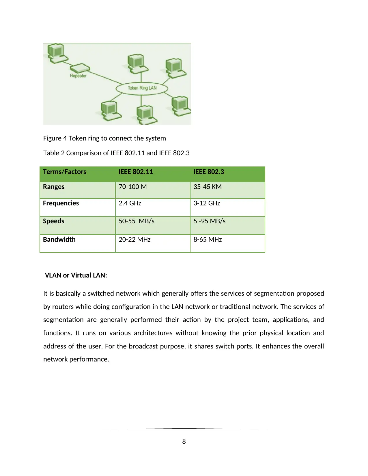
Figure 4 Token ring to connect the system
Table 2 Comparison of IEEE 802.11 and IEEE 802.3
Terms/Factors IEEE 802.11 IEEE 802.3
Ranges 70-100 M 35-45 KM
Frequencies 2.4 GHz 3-12 GHz
Speeds 50-55 MB/s 5 -95 MB/s
Bandwidth 20-22 MHz 8-65 MHz
VLAN or Virtual LAN:
It is basically a switched network which generally offers the services of segmentation proposed
by routers while doing configuration in the LAN network or traditional network. The services of
segmentation are generally performed their action by the project team, applications, and
functions. It runs on various architectures without knowing the prior physical location and
address of the user. For the broadcast purpose, it shares switch ports. It enhances the overall
network performance.
8
⊘ This is a preview!⊘
Do you want full access?
Subscribe today to unlock all pages.
Trusted by 1+ million students worldwide
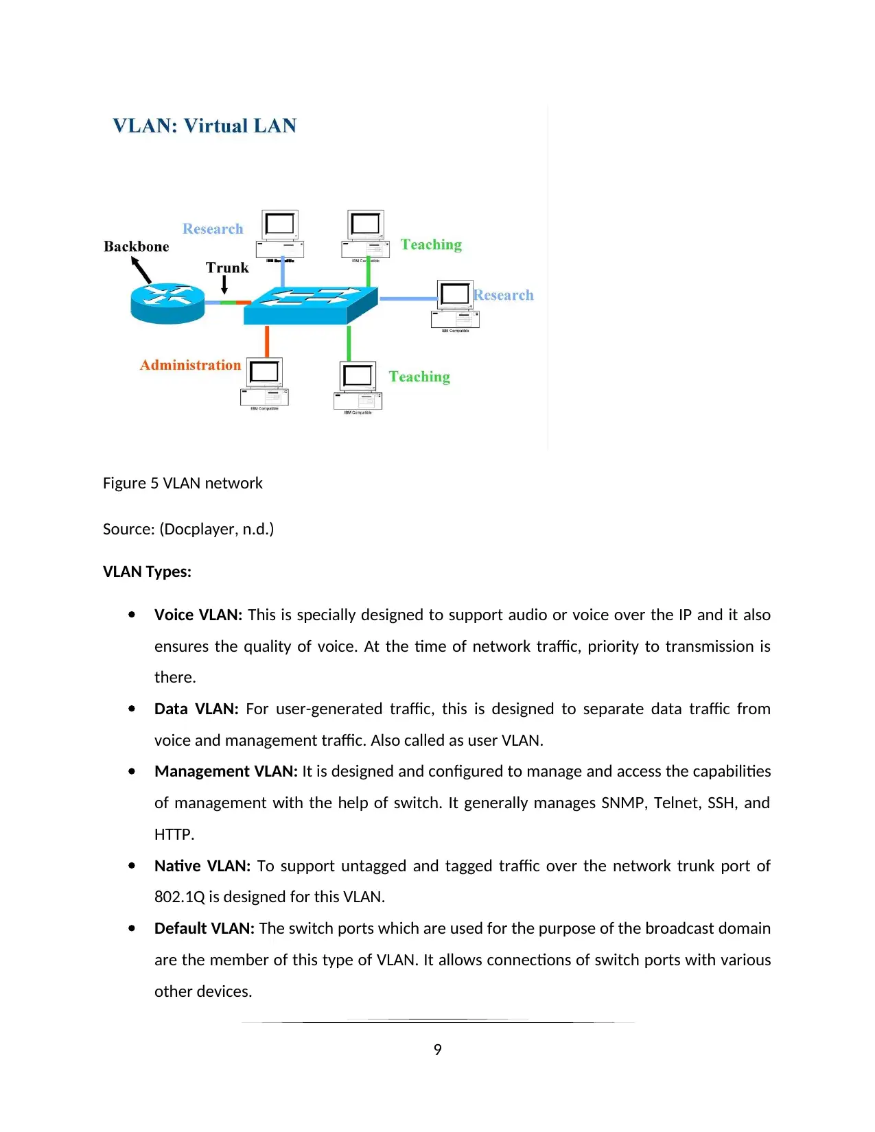
Figure 5 VLAN network
Source: (Docplayer, n.d.)
VLAN Types:
Voice VLAN: This is specially designed to support audio or voice over the IP and it also
ensures the quality of voice. At the time of network traffic, priority to transmission is
there.
Data VLAN: For user-generated traffic, this is designed to separate data traffic from
voice and management traffic. Also called as user VLAN.
Management VLAN: It is designed and configured to manage and access the capabilities
of management with the help of switch. It generally manages SNMP, Telnet, SSH, and
HTTP.
Native VLAN: To support untagged and tagged traffic over the network trunk port of
802.1Q is designed for this VLAN.
Default VLAN: The switch ports which are used for the purpose of the broadcast domain
are the member of this type of VLAN. It allows connections of switch ports with various
other devices.
9
Paraphrase This Document
Need a fresh take? Get an instant paraphrase of this document with our AI Paraphraser
VLAN Benefits:
Higher Performance: It generally works in multiple workgroups with some logic which
helps in reducing the traffic flow and keeps the performance high.
Mitigation of Broadcast Storm: The network of VLAN generally reduces the devices into
the storm broadcast because the network is divided.
Security: The sensitive data is separated from the VLAN network but which results in the
increase of confidential of the information.
Cost Reduction: Due to efficient bandwidth, the network cost is reduced
(itknowledgeexchange, 2018).
Communication Equipment for LAN data:
Various LAN equipment is:
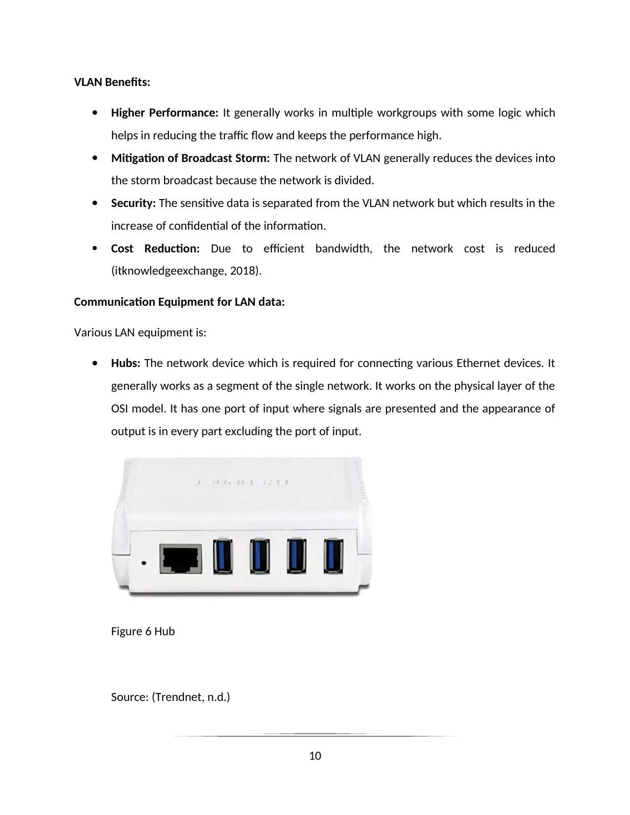
Hubs: The network device which is required for connecting various Ethernet devices. It
generally works as a segment of the single network. It works on the physical layer of the
OSI model. It has one port of input where signals are presented and the appearance of
output is in every part excluding the port of input.
Figure 6 Hub
Source: (Trendnet, n.d.)
10
Higher Performance: It generally works in multiple workgroups with some logic which
helps in reducing the traffic flow and keeps the performance high.
Mitigation of Broadcast Storm: The network of VLAN generally reduces the devices into
the storm broadcast because the network is divided.
Security: The sensitive data is separated from the VLAN network but which results in the
increase of confidential of the information.
Cost Reduction: Due to efficient bandwidth, the network cost is reduced
(itknowledgeexchange, 2018).
Communication Equipment for LAN data:
Various LAN equipment is:
Hubs: The network device which is required for connecting various Ethernet devices. It
generally works as a segment of the single network. It works on the physical layer of the
OSI model. It has one port of input where signals are presented and the appearance of
output is in every part excluding the port of input.
Figure 6 Hub
Source: (Trendnet, n.d.)
10
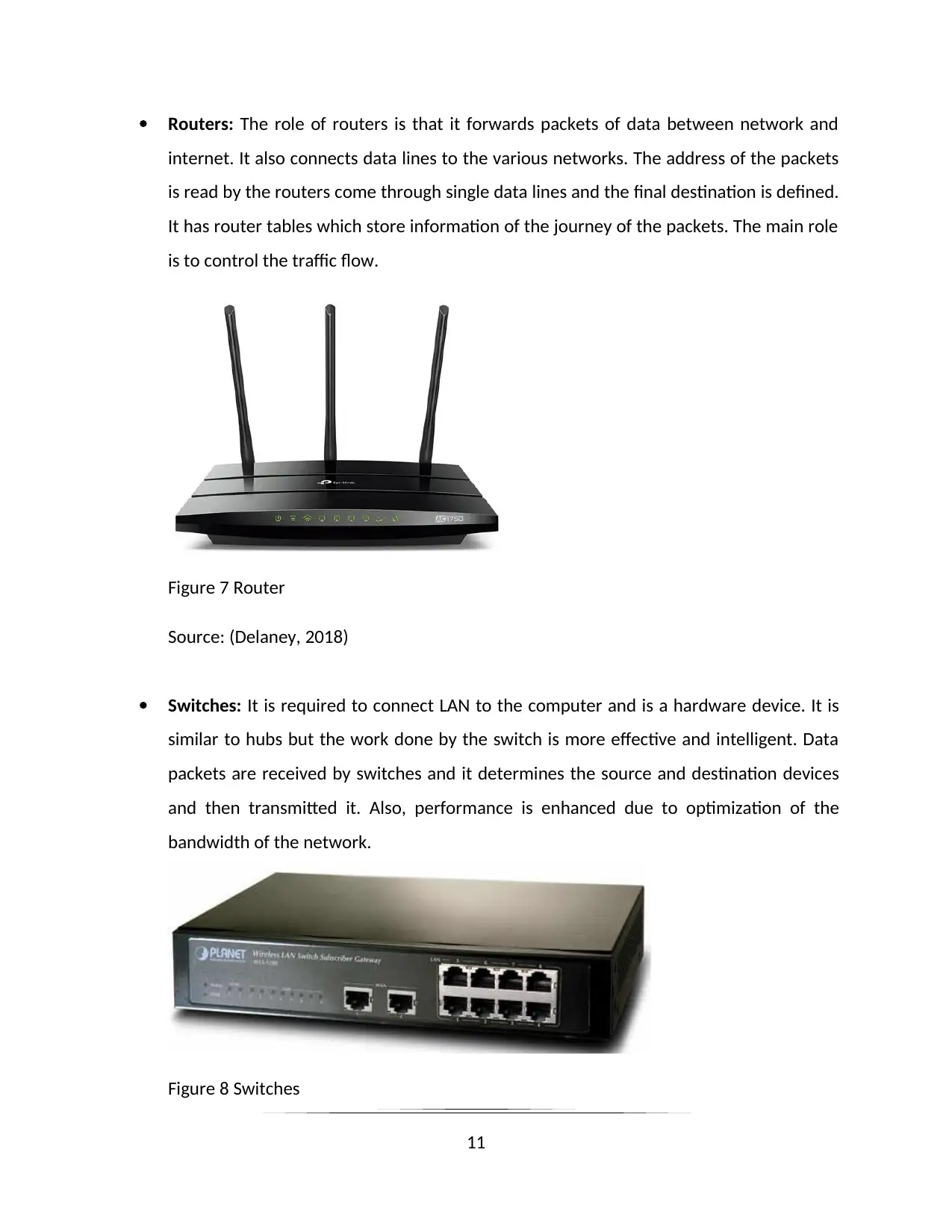
Routers: The role of routers is that it forwards packets of data between network and
internet. It also connects data lines to the various networks. The address of the packets
is read by the routers come through single data lines and the final destination is defined.
It has router tables which store information of the journey of the packets. The main role
is to control the traffic flow.
Figure 7 Router
Source: (Delaney, 2018)
Switches: It is required to connect LAN to the computer and is a hardware device. It is
similar to hubs but the work done by the switch is more effective and intelligent. Data
packets are received by switches and it determines the source and destination devices
and then transmitted it. Also, performance is enhanced due to optimization of the
bandwidth of the network.
Figure 8 Switches
11
⊘ This is a preview!⊘
Do you want full access?
Subscribe today to unlock all pages.
Trusted by 1+ million students worldwide
1 out of 47
Related Documents


Your All-in-One AI-Powered Toolkit for Academic Success.
+13062052269
info@desklib.com
Available 24*7 on WhatsApp / Email
![[object Object]](/_next/static/media/star-bottom.7253800d.svg)
Unlock your academic potential
Copyright © 2020–2026 A2Z Services. All Rights Reserved. Developed and managed by ZUCOL.