Comprehensive Report: LAN Infrastructure Design and Implementation
VerifiedAdded on 2024/06/27
|45
|4502
|135
Report
AI Summary
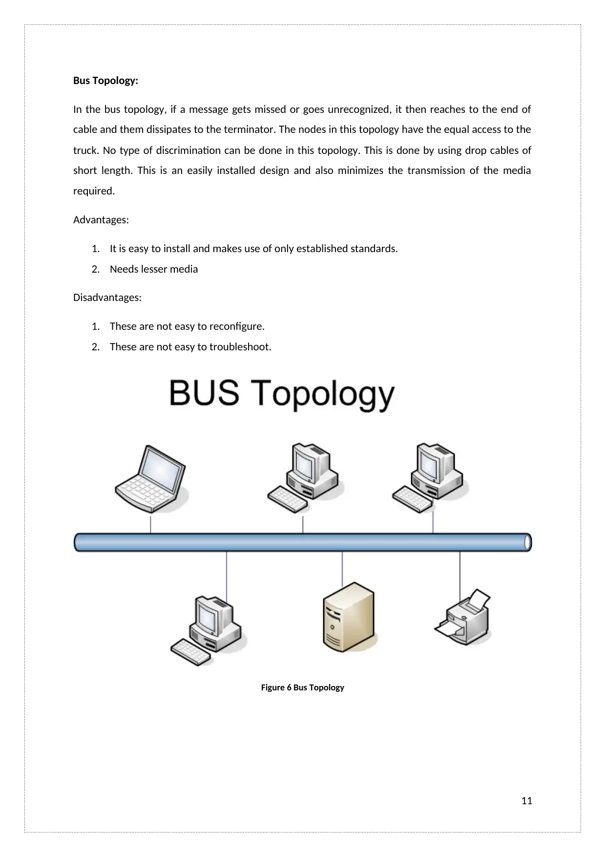
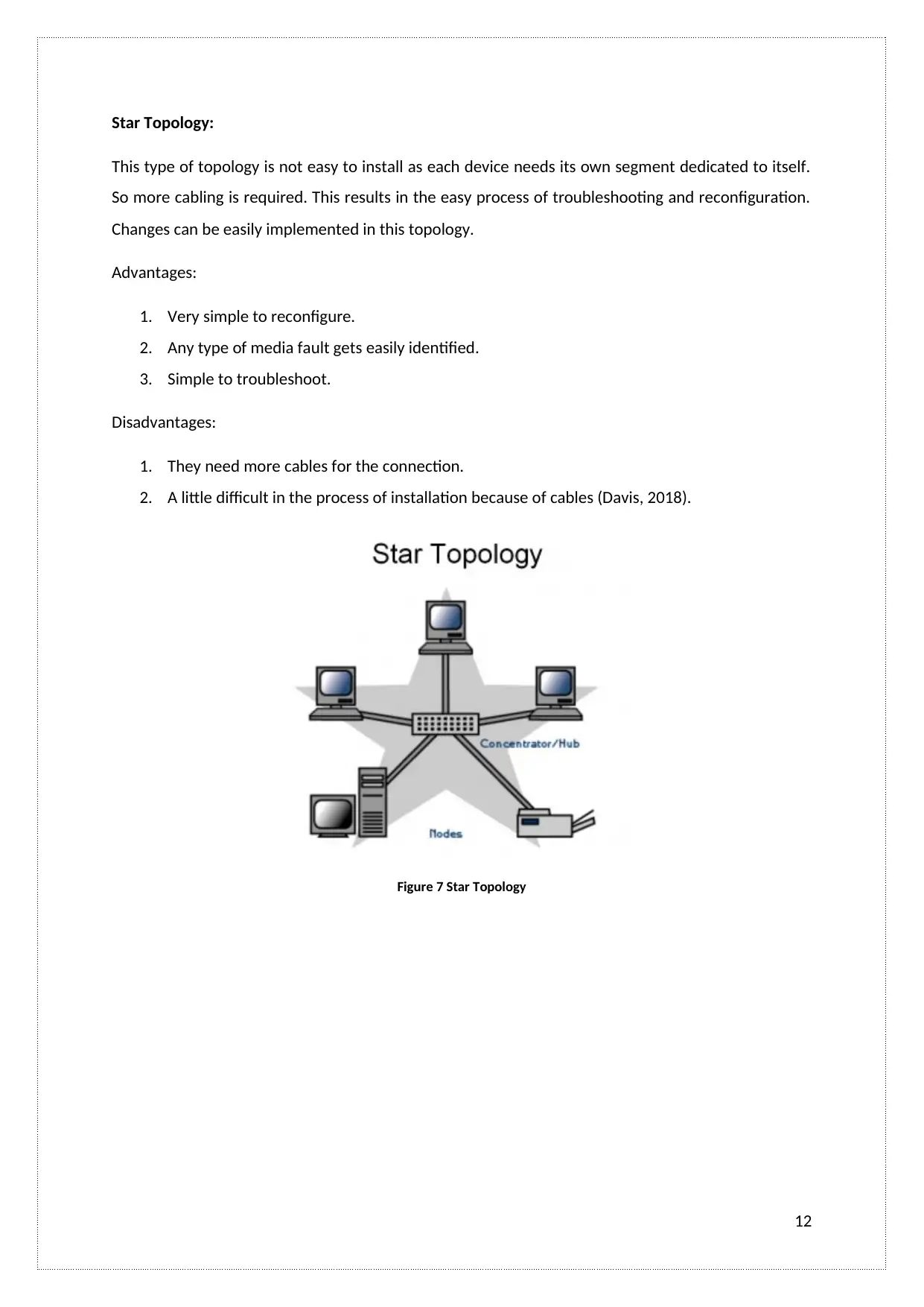
This report comprehensively covers the design, implementation, and management of a Local Area Network (LAN) infrastructure for a company. It details the design of the LAN, including the selection and evaluation of suitable components like switches, routers, and hubs, considering various network topologies such as ring, mesh, hybrid, bus, star, and cellular. The report outlines the practical steps involved in building and configuring the LAN, including the use of IPv4 and IPv6, and implementing essential services. Network security measures, such as VLAN trunking, access control lists, and router configurations, are implemented to protect data transmission. The report also includes a critical review and testing of the LAN to ensure its functionality and security. Post-implementation, the report discusses monitoring and management strategies, including troubleshooting techniques using commands like 'ping' and 'traceroute'. Finally, the report evaluates the LAN's performance and addresses issues to improve security, reliability, and overall performance, supported by figures illustrating network configurations and test results.

LOCAL AREA NETWORKING
TECHNOLOGIES
1
TECHNOLOGIES
1
Paraphrase This Document
Need a fresh take? Get an instant paraphrase of this document with our AI Paraphraser

Table of Contents
LO2 Be able to design LAN infrastructures............................................................................................5
A.C 2.1 Design a LAN infrastructure for the company which will facilitate all of their requirements 5
A.C 2.2 Critically evaluate the suitability of LAN components...........................................................7
LO3. Be able to implement LAN infrastructures..................................................................................14
A.C 3.1 Builds and configures a LAN (including services) to meet a given requirement..................14
A.C 3.2 Implements network security on a LAN...............................................................................22
A.C 3.3 Critically reviews and tests a LAN........................................................................................28
LO4. Be able to manage LAN infrastructures.......................................................................................34
A.C 4.1 Critically discusses how this LAN infrastructure will be monitored and managed (via
troubleshooting) if there is an issue during the post-implementation period.................................34
A.C 4.2 Resolves LAN issues to improve security, reliability and performance................................38
A.C 4.3 Critically evaluate the performance of a LAN......................................................................39
References:..........................................................................................................................................45
2

List of Figures
s
Figure 1 LAN network infrastructure 6
Figure 2 Ring Topology..........................................................................................................................8
Figure 3 Mesh Topology........................................................................................................................9
Figure 4 Tree network - hybrid topology.............................................................................................10
Figure 5 Ring-Star network - hybrid topology......................................................................................10
Figure 6 Bus Topology.........................................................................................................................11
Figure 7 Star Topology.........................................................................................................................12
Figure 8 Cellular topology....................................................................................................................13
Figure 9: LAN network solution...........................................................................................................15
Figure 10: Proposed LAN Network Metadata 1...................................................................................16
Figure 11: Proposed LAN Network Metadata 2...................................................................................17
Figure 12: Proposed LAN Network Metadata 3...................................................................................18
Figure 13: Proposed LAN Network Metadata 4...................................................................................18
Figure 14: Proposed LAN Network HTTP Server Domain.....................................................................19
Figure 15: Require LAN network proposal...........................................................................................19
Figure 16: Access of Telnet in the LAN network..................................................................................20
Figure 17: LAN network server such as DNS server.............................................................................20
Figure 18: LAN network server such as DHCP server...........................................................................21
Figure 19: Implementation of VLAN trunking as security purpose......................................................22
Figure 20: Implementation of Access control lists as security purpose...............................................23
Figure 21: Implementation of Router configuration as security purpose............................................24
Figure 22: Router configuration part 1................................................................................................25
Figure 23: Router configuration part 2................................................................................................26
Figure 24: Router configuration part 3................................................................................................27
Figure 25: Router configuration part 4................................................................................................27
Figure 26: Test case 1..........................................................................................................................29
Figure 27: Test case 2..........................................................................................................................30
Figure 28: Test case 3..........................................................................................................................30
Figure 29: Test case 4..........................................................................................................................31
Figure 30: Test case 5..........................................................................................................................31
Figure 31: Test case 6..........................................................................................................................32
Figure 32: : Test case 7........................................................................................................................32
3
⊘ This is a preview!⊘
Do you want full access?
Subscribe today to unlock all pages.

Trusted by 1+ million students worldwide

Figure 33: Test case 8.........................................................................................................................33
Figure 34: Testing of Paring command 1.............................................................................................35
Figure 35: Testing of Paring command 2.............................................................................................35
Figure 36: Testing of Ping command 1.................................................................................................36
Figure 37: Testing of Ping command 2.................................................................................................36
Figure 38: Testing of Ping command 3.................................................................................................37
Figure 39: Testing of Ping command 4.................................................................................................37
Figure 40: Ping command test 1..........................................................................................................39
Figure 41: Ping command test 2..........................................................................................................40
Figure 42: Ping command test 3..........................................................................................................40
Figure 43: Network design...................................................................................................................41
Figure 44: PDU list showing the failed connection between departments..........................................42
Figure 45: PDU list showing success connection between departments.............................................42
Figure 46: Ping command test 1..........................................................................................................42
Figure 47: Ping command test 2..........................................................................................................43
Figure 48: Ping command test 3..........................................................................................................43
4
Paraphrase This Document
Need a fresh take? Get an instant paraphrase of this document with our AI Paraphraser

LO2 Be able to design LAN infrastructures
A.C 2.1 Design a LAN infrastructure for the company which will facilitate all of their
requirements
Topology: It defines the physical arrangement of the devices used for the networking. These are
mainly driven by the two types of network connection. In the point-to-point type of connections,
there is a direct link which is established between the two devices. In the connections of multipoint
type, the link is established between multiple devices.
Technology: LAN is a network of data communication that connects different terminals in a
particular area. The connections of the devices can be wired or wireless. Following are the LAN
technologies:
Ethernet
Wireless LAN
Token Ring (Stallings, 2018)
5

Figure 1 LAN network infrastructure
6
6
⊘ This is a preview!⊘
Do you want full access?
Subscribe today to unlock all pages.

Trusted by 1+ million students worldwide

A.C 2.2 Critically evaluate the suitability of LAN components
Following are the components of the LAN:
1. Switch: This is a fundamental part of the network. They allow the nodes to communicate
with other nodes in an efficient and smooth manner. The switches in the LAN provide a
separate connection to each node in the internal network of the company. The switch then
creates a series of a network consisting of two devices.
2. Routers: Routers are the network devices that forward the packets of data among the
computer networks. The routers direct the functions on the internet. The data sent on the
internet is in the form of data packets. The routers forward these packets from routers to
other routers in the network. These routers are attached with many data lines of various
networks. The most common type of network is small office and home routers. These simply
forwards the IP packets.
3. Hubs: A hub is also called as a network hub. It acts as a common point of connection of the
devices that are used to connect with the segments of the LAN. A hub consists of many
ports. Whenever a packet comes at any of the port, it gets copied to other ports as well so as
to allow segments of LAN to see the packets. It acts as a central connection of all the
equipment of the network.
The Topologies of the LAN are
There are following types of LAN topologies:
1. Ring Topology
2. Mesh Topology
3. Hybrid Topology
4. Bus Topology
5. Star Topology
6. Cellular Topology
7
Paraphrase This Document
Need a fresh take? Get an instant paraphrase of this document with our AI Paraphraser

Ring Topology:
In this type of topology, the addresses do not match with each other so the nodes regenerate those
messages and then sends them. Then if the address gets matches, the node will accept the message
and then replies back to the real sender of the message. In the beginning, this topology was easy to
install but these require large media than other systems as the loops are needed to be closed. After
installing the ring, it gets more difficult to reconfigure them.
Advantages:
1. It is simple to troubleshoot them.
2. The workstations which get troubled gets identified easily in this topology.
Disadvantages:
1. It is difficult to reconfigure and install.
2. Any media failure can cause the whole network to fail.
Figure 2 Ring Topology
8

Mesh Topology:
It is exactly a design having point-to-point connections. Every device in this network have links
between them. However, this is not a practical design as this causes wastage of media throughout
the transmission. This is also difficult to reconfigure and install. In this, the number of devices
connected affects the speed of the communication. The most common example of this network is
Switched hubs and ATM.
Advantages:
1. It is simple to troubleshoot
2. Faults can be easily identified.
Disadvantages:
1. As a number of connections of devices increase, it gets difficult to reconfigure and install
this.
Figure 3 Mesh Topology
9
⊘ This is a preview!⊘
Do you want full access?
Subscribe today to unlock all pages.

Trusted by 1+ million students worldwide

Hybrid Topology:
It is the combination of pure network topology. Following are the hybrid topologies:
Tree network
Figure 4 Tree network - hybrid topology
Ring-Star network
Figure 5 Ring-Star network - hybrid topology
10
It is the combination of pure network topology. Following are the hybrid topologies:
Tree network
Figure 4 Tree network - hybrid topology
Ring-Star network
Figure 5 Ring-Star network - hybrid topology
10
Paraphrase This Document
Need a fresh take? Get an instant paraphrase of this document with our AI Paraphraser

Bus Topology:
In the bus topology, if a message gets missed or goes unrecognized, it then reaches to the end of
cable and them dissipates to the terminator. The nodes in this topology have the equal access to the
truck. No type of discrimination can be done in this topology. This is done by using drop cables of
short length. This is an easily installed design and also minimizes the transmission of the media
required.
Advantages:
1. It is easy to install and makes use of only established standards.
2. Needs lesser media
Disadvantages:
1. These are not easy to reconfigure.
2. These are not easy to troubleshoot.
Figure 6 Bus Topology
11

Star Topology:
This type of topology is not easy to install as each device needs its own segment dedicated to itself.
So more cabling is required. This results in the easy process of troubleshooting and reconfiguration.
Changes can be easily implemented in this topology.
Advantages:
1. Very simple to reconfigure.
2. Any type of media fault gets easily identified.
3. Simple to troubleshoot.
Disadvantages:
1. They need more cables for the connection.
2. A little difficult in the process of installation because of cables (Davis, 2018).
Figure 7 Star Topology
12
⊘ This is a preview!⊘
Do you want full access?
Subscribe today to unlock all pages.

Trusted by 1+ million students worldwide
1 out of 45
Related Documents

Your All-in-One AI-Powered Toolkit for Academic Success.
+13062052269
info@desklib.com
Available 24*7 on WhatsApp / Email
Unlock your academic potential
Copyright © 2020–2025 A2Z Services. All Rights Reserved. Developed and managed by ZUCOL.