Comprehensive LAN Infrastructure: Design, Implementation, and Security
VerifiedAdded on 2024/06/07
|43
|4996
|331
Report
AI Summary
This report provides a detailed exploration of Local Area Network (LAN) infrastructure, focusing on the design, implementation, and management of a network for Footfall filed marketing ltd. The report begins by discussing various network topologies such as Bus, Star, Mesh, Tree, and Ring, evaluating their suitability for different requirements. It then delves into the critical evaluation of LAN components, including repeaters, routers, network servers, bridges, hubs, and switches, alongside server, client, and network software. The implementation phase, utilizing Cisco Packet Tracer, outlines the construction and configuration of a LAN to meet specific organizational needs, including inter-departmental communication across three floors, detailing metadata and the activation of DNS and DHCP servers. Network security measures, such as router configuration, ACL, and VLAN implementation, are discussed to protect sensitive information. The report further includes comprehensive testing and troubleshooting procedures to ensure network functionality, reliability, and performance, culminating in a critical evaluation of the implemented LAN and recommendations for improvements, with a final conclusion summarizing the project and its outcomes. This report is designed to provide a comprehensive understanding of LAN infrastructure management and security.

LOCAL AREA NETWORK
Paraphrase This Document
Need a fresh take? Get an instant paraphrase of this document with our AI Paraphraser
Contents
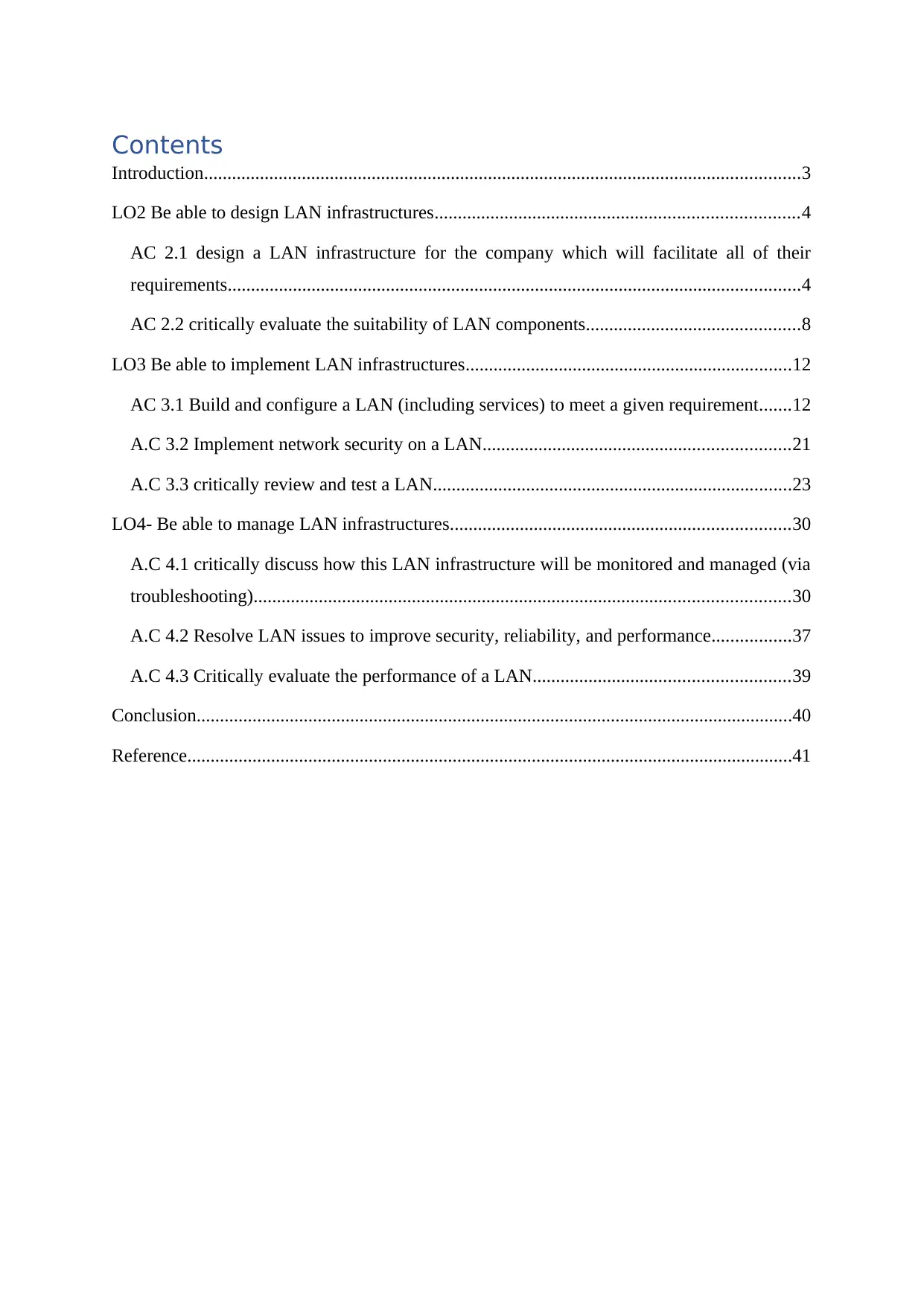
Introduction................................................................................................................................3
LO2 Be able to design LAN infrastructures..............................................................................4
AC 2.1 design a LAN infrastructure for the company which will facilitate all of their
requirements...........................................................................................................................4
AC 2.2 critically evaluate the suitability of LAN components..............................................8
LO3 Be able to implement LAN infrastructures......................................................................12
AC 3.1 Build and configure a LAN (including services) to meet a given requirement.......12
A.C 3.2 Implement network security on a LAN..................................................................21
A.C 3.3 critically review and test a LAN.............................................................................23
LO4- Be able to manage LAN infrastructures.........................................................................30
A.C 4.1 critically discuss how this LAN infrastructure will be monitored and managed (via
troubleshooting)...................................................................................................................30
A.C 4.2 Resolve LAN issues to improve security, reliability, and performance.................37
A.C 4.3 Critically evaluate the performance of a LAN.......................................................39
Conclusion................................................................................................................................40
Reference..................................................................................................................................41
List of Figures
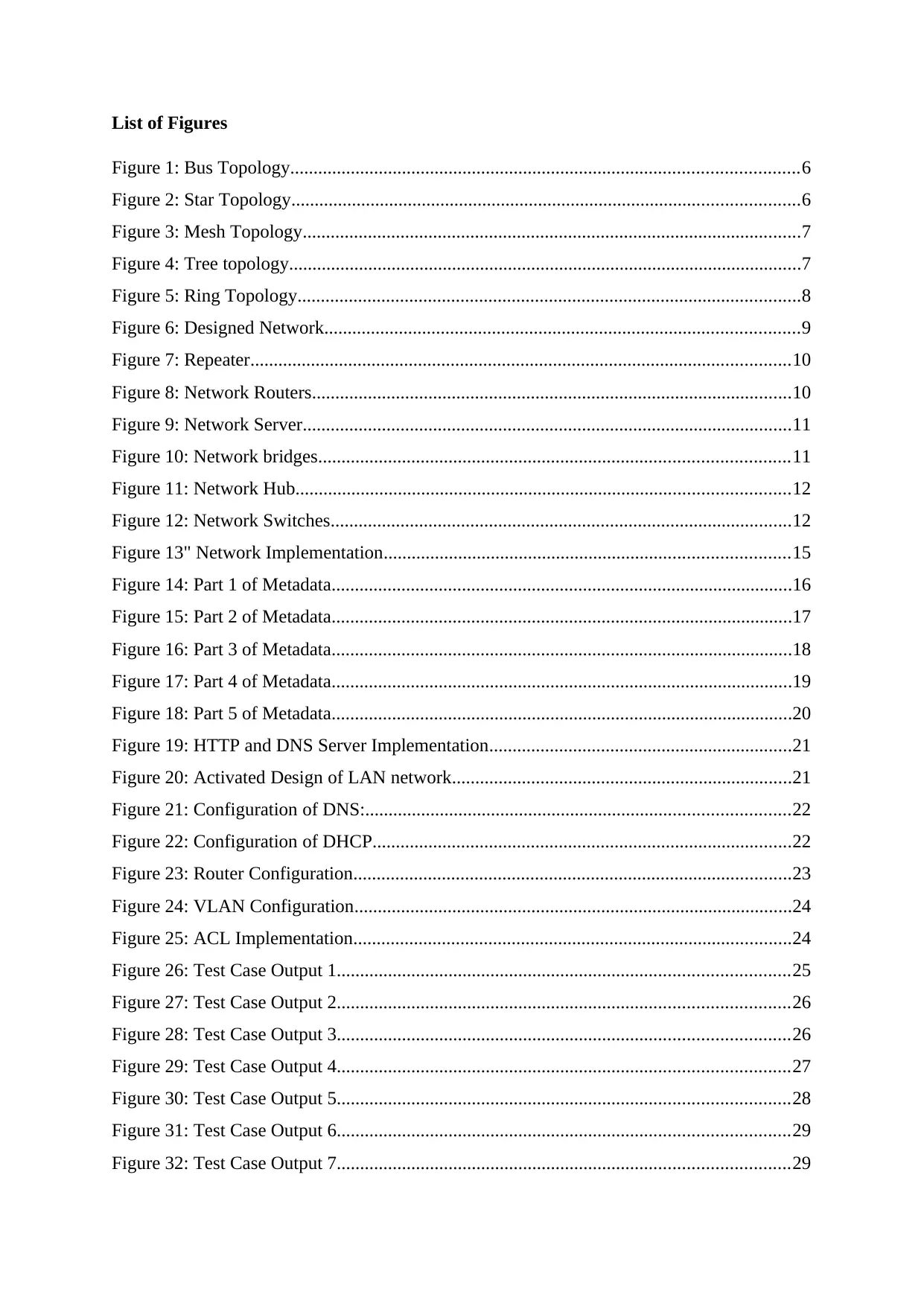
Figure 1: Bus Topology.............................................................................................................6
Figure 2: Star Topology.............................................................................................................6
Figure 3: Mesh Topology...........................................................................................................7
Figure 4: Tree topology..............................................................................................................7
Figure 5: Ring Topology............................................................................................................8
Figure 6: Designed Network......................................................................................................9
Figure 7: Repeater....................................................................................................................10
Figure 8: Network Routers.......................................................................................................10
Figure 9: Network Server.........................................................................................................11
Figure 10: Network bridges.....................................................................................................11
Figure 11: Network Hub..........................................................................................................12
Figure 12: Network Switches...................................................................................................12
Figure 13" Network Implementation.......................................................................................15
Figure 14: Part 1 of Metadata...................................................................................................16
Figure 15: Part 2 of Metadata...................................................................................................17
Figure 16: Part 3 of Metadata...................................................................................................18
Figure 17: Part 4 of Metadata...................................................................................................19
Figure 18: Part 5 of Metadata...................................................................................................20
Figure 19: HTTP and DNS Server Implementation.................................................................21
Figure 20: Activated Design of LAN network.........................................................................21
Figure 21: Configuration of DNS:...........................................................................................22
Figure 22: Configuration of DHCP..........................................................................................22
Figure 23: Router Configuration..............................................................................................23
Figure 24: VLAN Configuration..............................................................................................24
Figure 25: ACL Implementation..............................................................................................24
Figure 26: Test Case Output 1.................................................................................................25
Figure 27: Test Case Output 2.................................................................................................26
Figure 28: Test Case Output 3.................................................................................................26
Figure 29: Test Case Output 4.................................................................................................27
Figure 30: Test Case Output 5.................................................................................................28
Figure 31: Test Case Output 6.................................................................................................29
Figure 32: Test Case Output 7.................................................................................................29
⊘ This is a preview!⊘
Do you want full access?
Subscribe today to unlock all pages.

Trusted by 1+ million students worldwide
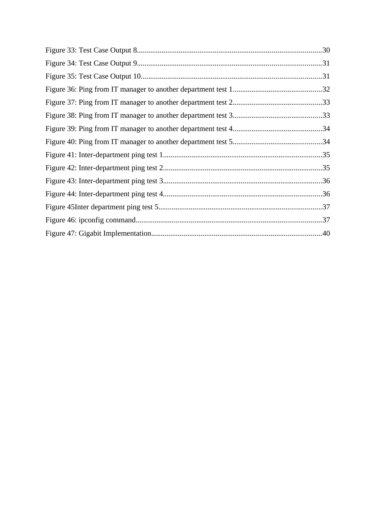
Figure 33: Test Case Output 8.................................................................................................30
Figure 34: Test Case Output 9.................................................................................................31
Figure 35: Test Case Output 10...............................................................................................31
Figure 36: Ping from IT manager to another department test 1...............................................32
Figure 37: Ping from IT manager to another department test 2...............................................33
Figure 38: Ping from IT manager to another department test 3...............................................33
Figure 39: Ping from IT manager to another department test 4...............................................34
Figure 40: Ping from IT manager to another department test 5...............................................34
Figure 41: Inter-department ping test 1....................................................................................35
Figure 42: Inter-department ping test 2....................................................................................35
Figure 43: Inter-department ping test 3....................................................................................36
Figure 44: Inter-department ping test 4....................................................................................36
Figure 45Inter department ping test 5......................................................................................37
Figure 46: ipconfig command..................................................................................................37
Figure 47: Gigabit Implementation..........................................................................................40
Paraphrase This Document
Need a fresh take? Get an instant paraphrase of this document with our AI Paraphraser
Introduction
Local area network is the collection of components that are used to communicate within the
network through wired or wireless medium. In this report network for Footfall filed
marketing ltd. is going to be implemented so that they can communicate in between the inter-
department of their organization within the three different floors.
In the first phase of report different network designs with different topologies are going to be
explained with different network components. In the second phase of the report, different
components that are used in the network are going to be explained with the network design.
In the third phase, the network will be implemented in Cisco Packet Tracer according to the
user requirements along with several ping test are also performed over the network to check
the proper functionality. In the last phase, the implemented network is been evaluated with
network security and reliability.
LO2 Be able to design LAN infrastructures
AC 2.1 design a LAN infrastructure for the company which will facilitate all of
their requirements
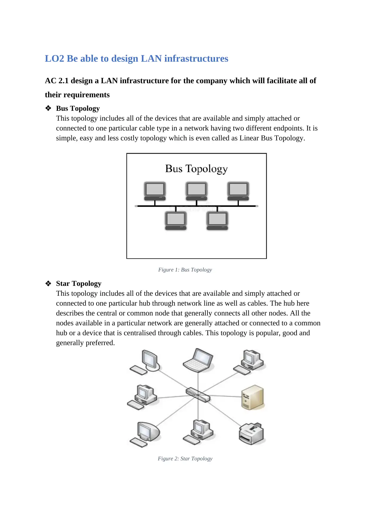
Bus Topology
This topology includes all of the devices that are available and simply attached or
connected to one particular cable type in a network having two different endpoints. It is
simple, easy and less costly topology which is even called as Linear Bus Topology.
Figure 1: Bus Topology
Star Topology
This topology includes all of the devices that are available and simply attached or
connected to one particular hub through network line as well as cables. The hub here
describes the central or common node that generally connects all other nodes. All the
nodes available in a particular network are generally attached or connected to a common
hub or a device that is centralised through cables. This topology is popular, good and
generally preferred.
Figure 2: Star Topology
⊘ This is a preview!⊘
Do you want full access?
Subscribe today to unlock all pages.

Trusted by 1+ million students worldwide
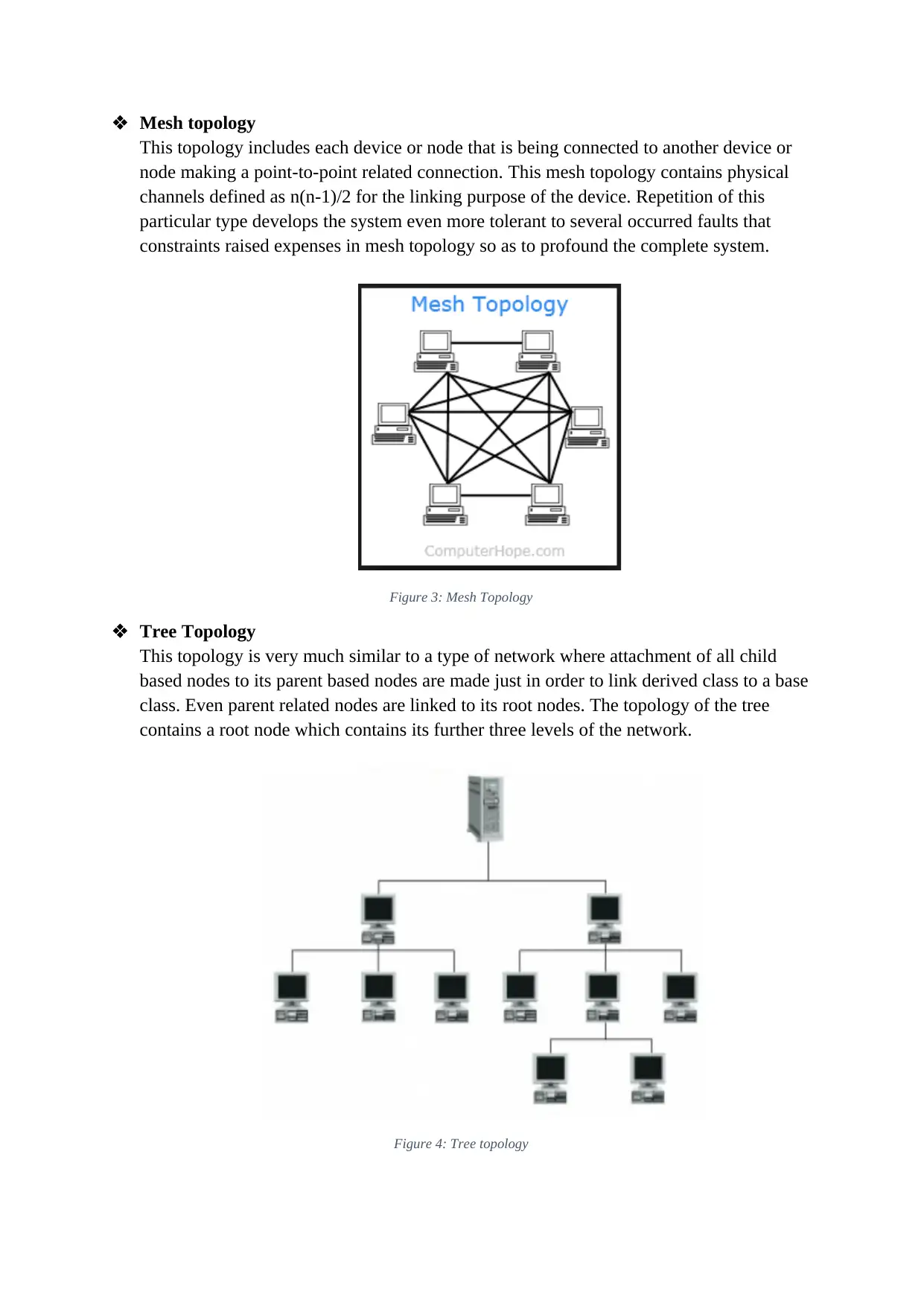
Mesh topology
This topology includes each device or node that is being connected to another device or
node making a point-to-point related connection. This mesh topology contains physical
channels defined as n(n-1)/2 for the linking purpose of the device. Repetition of this
particular type develops the system even more tolerant to several occurred faults that
constraints raised expenses in mesh topology so as to profound the complete system.
Figure 3: Mesh Topology
Tree Topology
This topology is very much similar to a type of network where attachment of all child
based nodes to its parent based nodes are made just in order to link derived class to a base
class. Even parent related nodes are linked to its root nodes. The topology of the tree
contains a root node which contains its further three levels of the network.
Figure 4: Tree topology
Paraphrase This Document
Need a fresh take? Get an instant paraphrase of this document with our AI Paraphraser
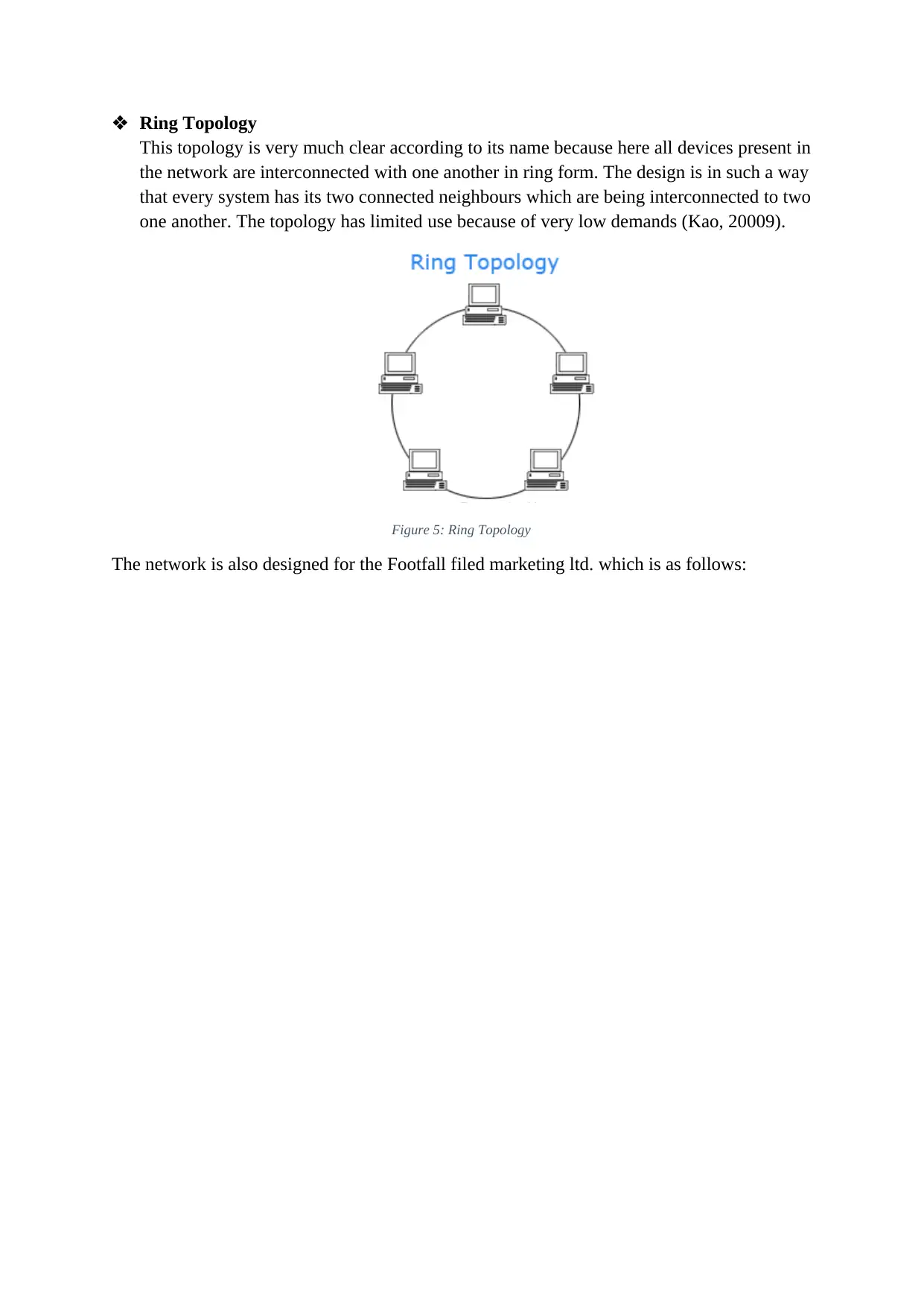
Ring Topology
This topology is very much clear according to its name because here all devices present in
the network are interconnected with one another in ring form. The design is in such a way
that every system has its two connected neighbours which are being interconnected to two
one another. The topology has limited use because of very low demands (Kao, 20009).
Figure 5: Ring Topology
The network is also designed for the Footfall filed marketing ltd. which is as follows:
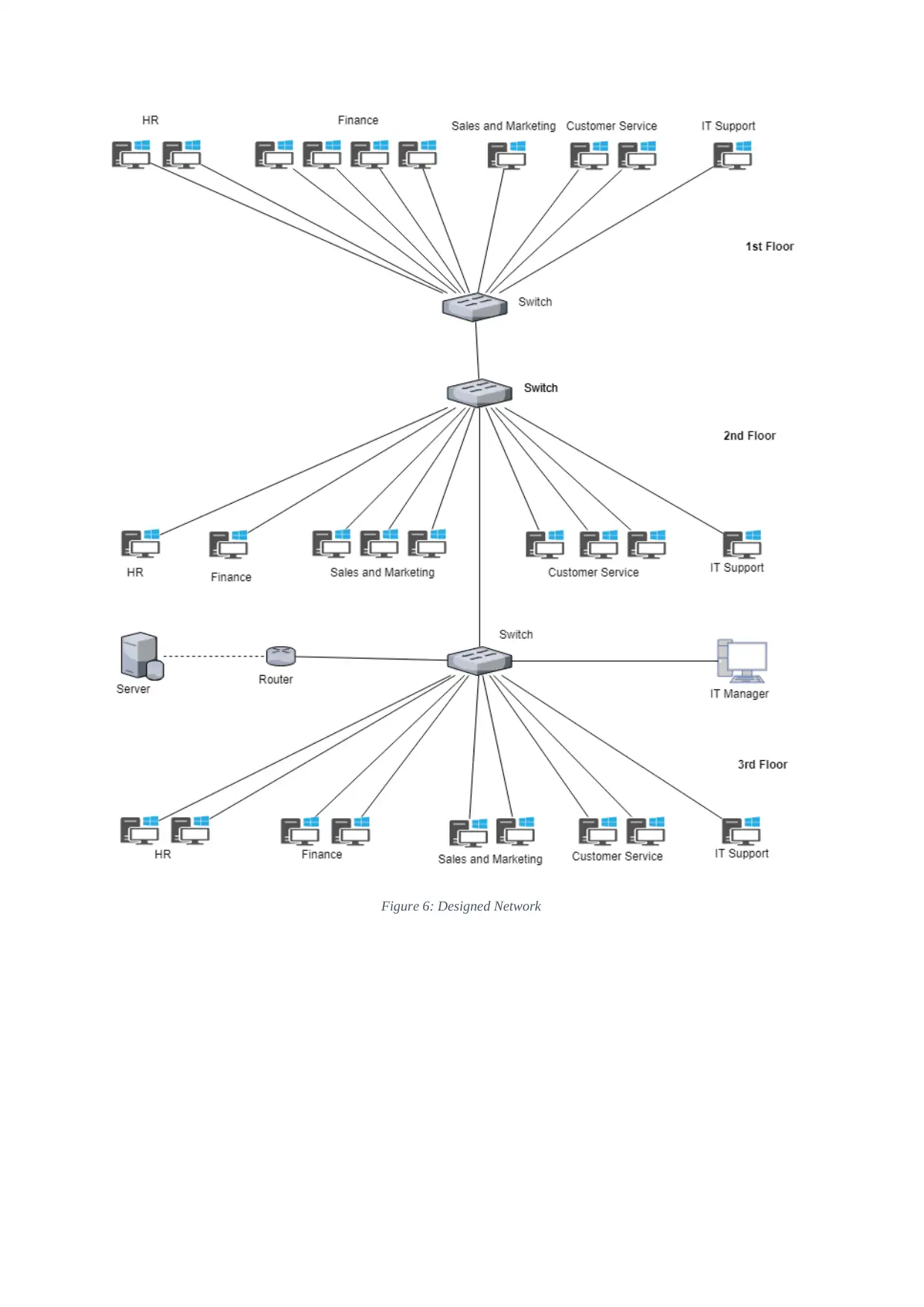
Figure 6: Designed Network
⊘ This is a preview!⊘
Do you want full access?
Subscribe today to unlock all pages.

Trusted by 1+ million students worldwide
AC 2.2 critically evaluate the suitability of LAN components
Various types of software and hardware components are being used in order to develop the
networks of LAN that are defined as:
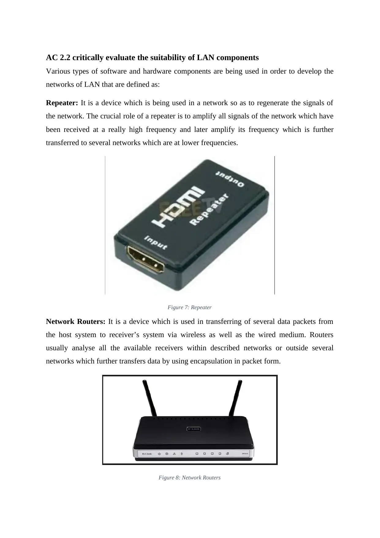
Repeater: It is a device which is being used in a network so as to regenerate the signals of
the network. The crucial role of a repeater is to amplify all signals of the network which have
been received at a really high frequency and later amplify its frequency which is further
transferred to several networks which are at lower frequencies.
Figure 7: Repeater
Network Routers: It is a device which is used in transferring of several data packets from
the host system to receiver’s system via wireless as well as the wired medium. Routers
usually analyse all the available receivers within described networks or outside several
networks which further transfers data by using encapsulation in packet form.
Figure 8: Network Routers
Paraphrase This Document
Need a fresh take? Get an instant paraphrase of this document with our AI Paraphraser
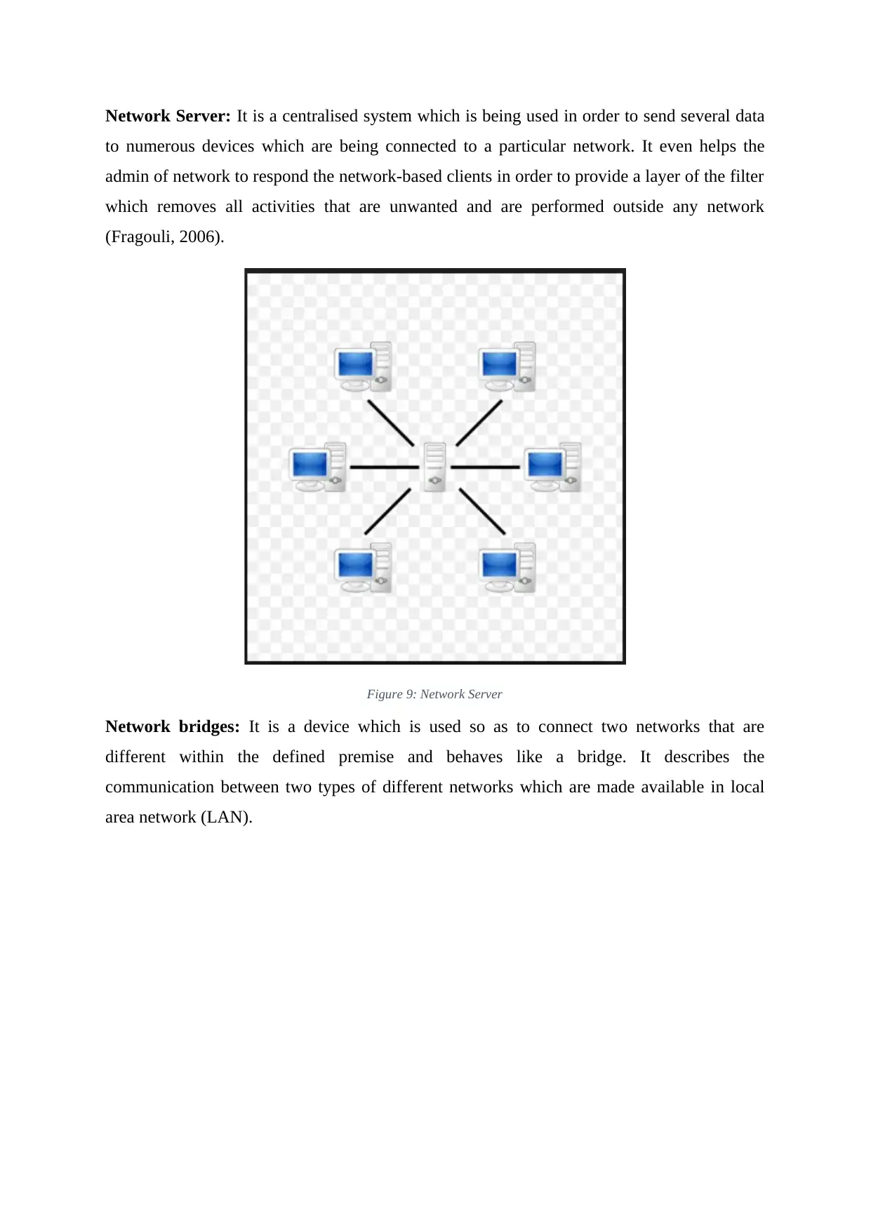
Network Server: It is a centralised system which is being used in order to send several data
to numerous devices which are being connected to a particular network. It even helps the
admin of network to respond the network-based clients in order to provide a layer of the filter
which removes all activities that are unwanted and are performed outside any network
(Fragouli, 2006).
Figure 9: Network Server
Network bridges: It is a device which is used so as to connect two networks that are
different within the defined premise and behaves like a bridge. It describes the
communication between two types of different networks which are made available in local
area network (LAN).
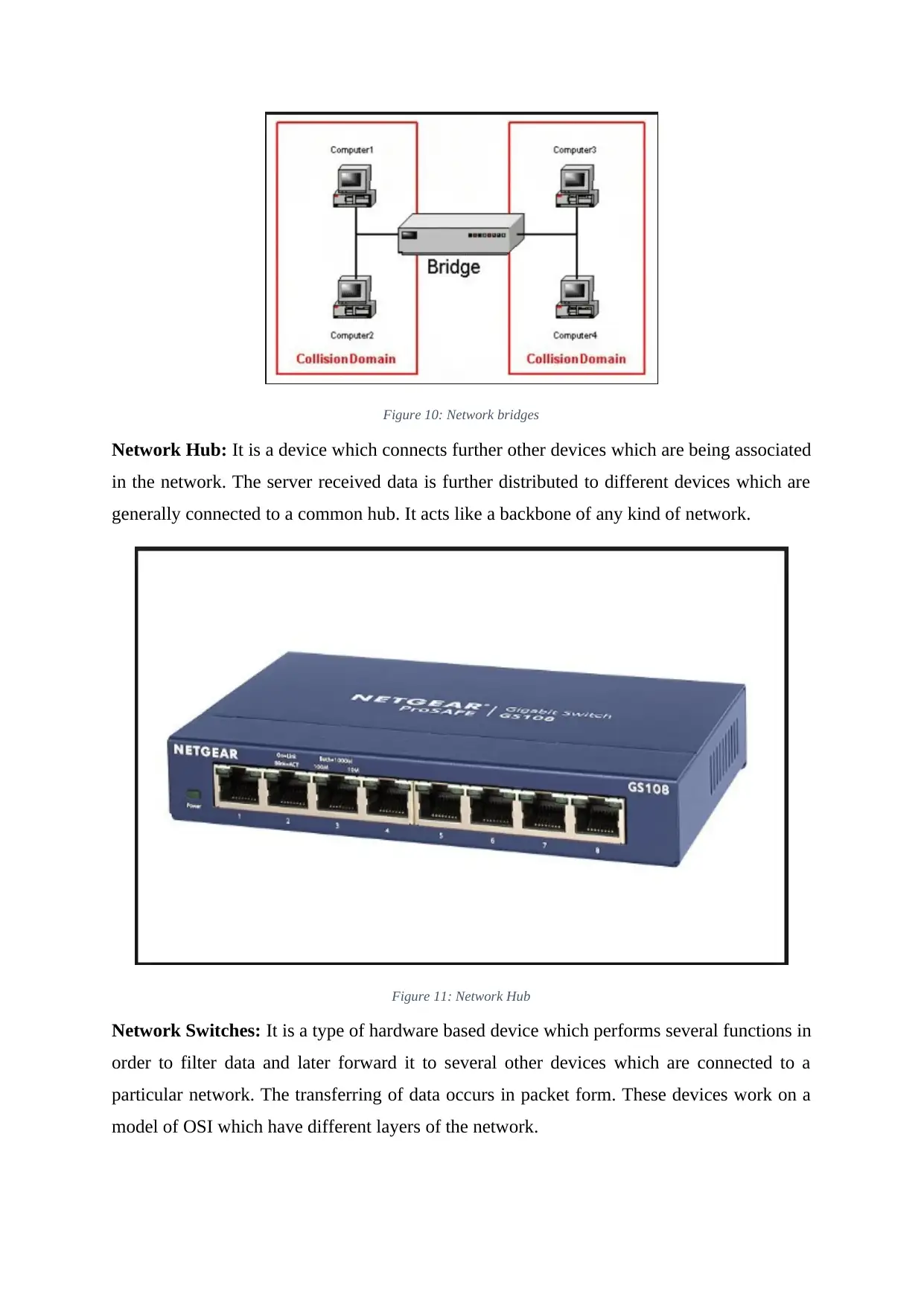
Figure 10: Network bridges
Network Hub: It is a device which connects further other devices which are being associated
in the network. The server received data is further distributed to different devices which are
generally connected to a common hub. It acts like a backbone of any kind of network.
Figure 11: Network Hub
Network Switches: It is a type of hardware based device which performs several functions in
order to filter data and later forward it to several other devices which are connected to a
particular network. The transferring of data occurs in packet form. These devices work on a
model of OSI which have different layers of the network.
⊘ This is a preview!⊘
Do you want full access?
Subscribe today to unlock all pages.

Trusted by 1+ million students worldwide
1 out of 43
Related Documents
Your All-in-One AI-Powered Toolkit for Academic Success.
+13062052269
info@desklib.com
Available 24*7 on WhatsApp / Email
![[object Object]](/_next/static/media/star-bottom.7253800d.svg)
Unlock your academic potential
Copyright © 2020–2026 A2Z Services. All Rights Reserved. Developed and managed by ZUCOL.


