Comprehensive Report on LAN Switching, Security, and Network Design
VerifiedAdded on 2023/04/05
|18
|4058
|217
Report
AI Summary
This report provides a detailed analysis of LAN switching concepts, security protocols, Ethernet switching network design, and wireless LAN switching. It begins by examining internetworking devices such as bridges, switches, and routers, emphasizing their roles in efficient data transmission. The report evaluates different switching techniques, including circuit switching and packet switching, highlighting the benefits of packet switching for modern networks. Using a Cisco switch as an example, the report demonstrates basic switch configuration steps, including setting access passwords, configuring Layer 3 addresses, and implementing port security. Furthermore, it investigates network security concepts like firewalls and explores various VLAN attacks, such as VLAN hopping and ARP attacks, along with methods to mitigate these threats. The report also contrasts Layer 2 and Layer 3 switching, evaluates the industrial applications of Ethernet switching, and presents an Ethernet switch network design incorporating VLAN concepts. Finally, it delves into wireless LAN switching, analyzing its architecture, traffic management, and monitoring techniques, providing a comprehensive overview of key aspects in modern network infrastructures. Desklib provides solved assignments for students.
Switch Engineering 1
Switch Engineering
Student’s Name:
Instructor’s Name:
Date:
Switch Engineering
Student’s Name:
Instructor’s Name:
Date:
Paraphrase This Document
Need a fresh take? Get an instant paraphrase of this document with our AI Paraphraser
Switch Engineering 2
Contents
Task 1 – Investigate the LAN Switching...........................................................2
1. Analyse the concept of Internetworking and the devices used................2
2. Evaluate the concept of Switching...........................................................3
Circuit Switching........................................................................................4
Packet switching........................................................................................4
3. Taking an example of Cisco Switch, demonstrate the basic Switch.........4
Task 2 – Investigate and design Switching Security........................................8
1. Examine the Network Security Concepts..................................................8
2. Explain the different types of VLAN attacks.............................................9
3. Review Random Frame-Stress Attacks...................................................10
Task 3 – Understand the concepts underlying Ethernet Switching Network
Design............................................................................................................11
1. Analyse the Ethernet Switching..............................................................11
2. Contrast the difference between layer 2 and Layer 3 Switching............12
3. Evaluate on the industrial application of Ethernet Switching.................13
4. Demonstrate Ethernet switch Network Design of the above case study
using the concepts of VLAN........................................................................14
Task 4 – Investigate and critically evaluate the Wireless LAN Switching.......15
1. Demonstrate on how Wireless Switching works.....................................15
2. Analyse WLAN Switching Architecture....................................................16
3. Evaluate Wireless Traffics.......................................................................16
4. Evaluate Wireless Management and Monitoring.....................................17
Task 1 – Investigate the LAN Switching
1. Analyse the concept of Internetworking and the devices
used
As Creative Consultant becomes a bigger and complex network, it is necessary for various
internetworking devices to be used. These devices are active components rather than simple
passive ones. They are active because internetworking devices are capable of doing more than
just sending data across different components in the network (Cisco, 1998). The internetworking
Switch Engineering 3
devices are responsible for making many smart decisions. They are responsible for interpreting,
reformatting and directing data through the different Creative Consultant network lines.
Internetworking devices usually operate in the OSI model layers. It does not function in the
physical layer.
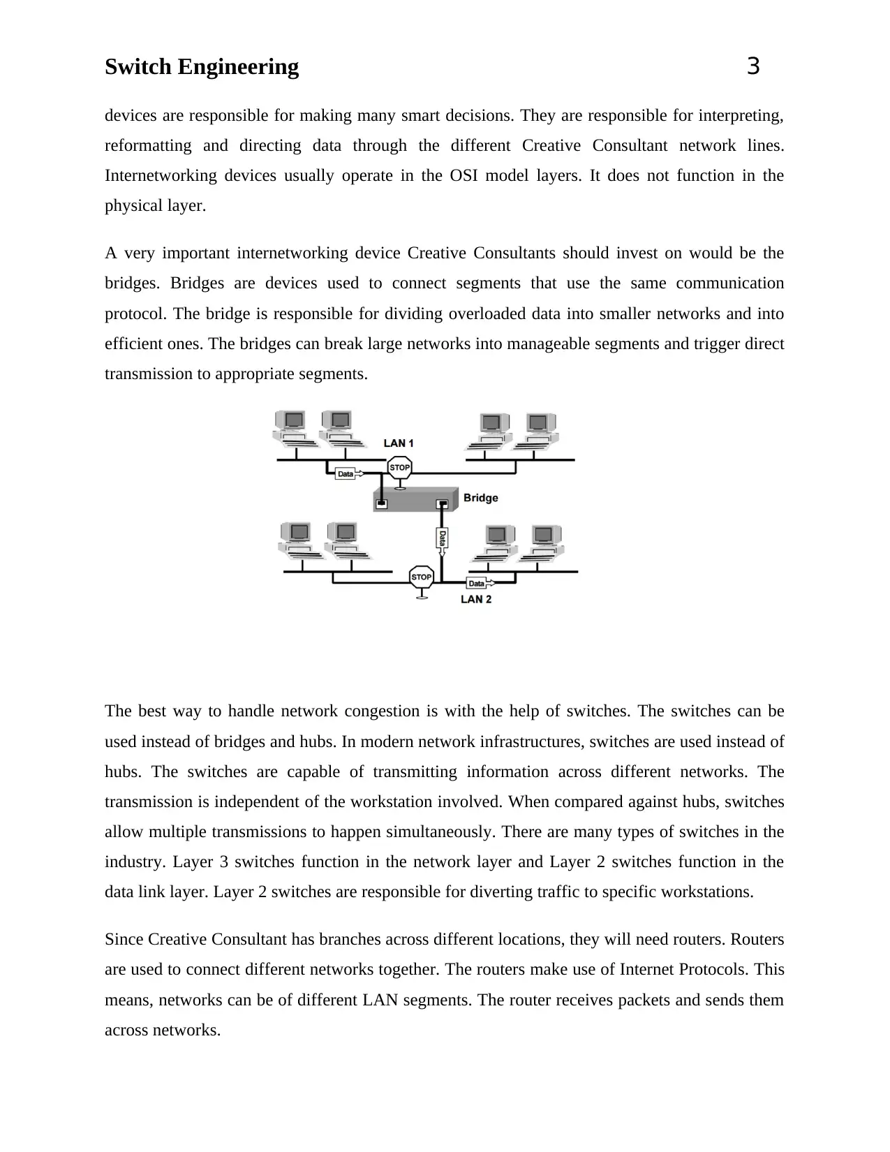
A very important internetworking device Creative Consultants should invest on would be the
bridges. Bridges are devices used to connect segments that use the same communication
protocol. The bridge is responsible for dividing overloaded data into smaller networks and into
efficient ones. The bridges can break large networks into manageable segments and trigger direct
transmission to appropriate segments.
The best way to handle network congestion is with the help of switches. The switches can be
used instead of bridges and hubs. In modern network infrastructures, switches are used instead of
hubs. The switches are capable of transmitting information across different networks. The
transmission is independent of the workstation involved. When compared against hubs, switches
allow multiple transmissions to happen simultaneously. There are many types of switches in the
industry. Layer 3 switches function in the network layer and Layer 2 switches function in the
data link layer. Layer 2 switches are responsible for diverting traffic to specific workstations.
Since Creative Consultant has branches across different locations, they will need routers. Routers
are used to connect different networks together. The routers make use of Internet Protocols. This
means, networks can be of different LAN segments. The router receives packets and sends them
across networks.
devices are responsible for making many smart decisions. They are responsible for interpreting,
reformatting and directing data through the different Creative Consultant network lines.
Internetworking devices usually operate in the OSI model layers. It does not function in the
physical layer.
A very important internetworking device Creative Consultants should invest on would be the
bridges. Bridges are devices used to connect segments that use the same communication
protocol. The bridge is responsible for dividing overloaded data into smaller networks and into
efficient ones. The bridges can break large networks into manageable segments and trigger direct
transmission to appropriate segments.
The best way to handle network congestion is with the help of switches. The switches can be
used instead of bridges and hubs. In modern network infrastructures, switches are used instead of
hubs. The switches are capable of transmitting information across different networks. The
transmission is independent of the workstation involved. When compared against hubs, switches
allow multiple transmissions to happen simultaneously. There are many types of switches in the
industry. Layer 3 switches function in the network layer and Layer 2 switches function in the
data link layer. Layer 2 switches are responsible for diverting traffic to specific workstations.
Since Creative Consultant has branches across different locations, they will need routers. Routers
are used to connect different networks together. The routers make use of Internet Protocols. This
means, networks can be of different LAN segments. The router receives packets and sends them
across networks.
⊘ This is a preview!⊘
Do you want full access?
Subscribe today to unlock all pages.
Trusted by 1+ million students worldwide
Switch Engineering 4
In the industry, Gateways are required to connect multi-purpose devices. The gateways are
responsible for converting one format of data to another. In some cases, gateways can be treated
as routers.
2. Evaluate the concept of Switching
For Creative Consultant to communicate and transfer data across networks, devices should be
able to communicate. A solution to effective communication between devices would be
switching. In a switched network topology, there are several interconnected nodes. These nodes
are used to transfer information from one source to another destination. The nodes can take
different routes. The route taken by a node is controlled by its switching mechanism. The end
and target devices that wish to be a part of the communication are known as stations. The
switching devices involved in the communication are known as nodes. In a switched network,
the following features will be seen:
1) The network topology does not have to be regular
2) Switched networks can use ATM or FDM for communication
3) There can be multiple paths between source and destination nodes
4) The switches are not worried about the type of data transferred
5) The switches should make sure data reaches the end by moving across nodes
There are three major types of switching techniques:
1) Packet switching
2) Circuit switching
3) Message switching
Circuit Switching
In this switching technique, there are dedicated paths between stations. A sequence of links is
established between the nodes. On the physical link there is a dedicated logical channel. This is a
technique employed in the telephony. However, creative consultants cannot used circuit
switching for their network. They should opt for packet switching.
Paraphrase This Document
Need a fresh take? Get an instant paraphrase of this document with our AI Paraphraser
Switch Engineering 5
Packet switching
During packet switching, data is broken into small packets. Long messages can be broken into a
series of smaller packets. Each packet is built with control information. Control information is
necessary for routing. Based on the routing information, packets are sent from one source and
stored in the destination (the packets cross a series of nodes in between). Major benefits in using
packet switching would be as follows:
1) Better data rate conversion
2) Line efficiency
3) Packets can be transferred even when the network is very busy
4) Priorities can be used to define packets
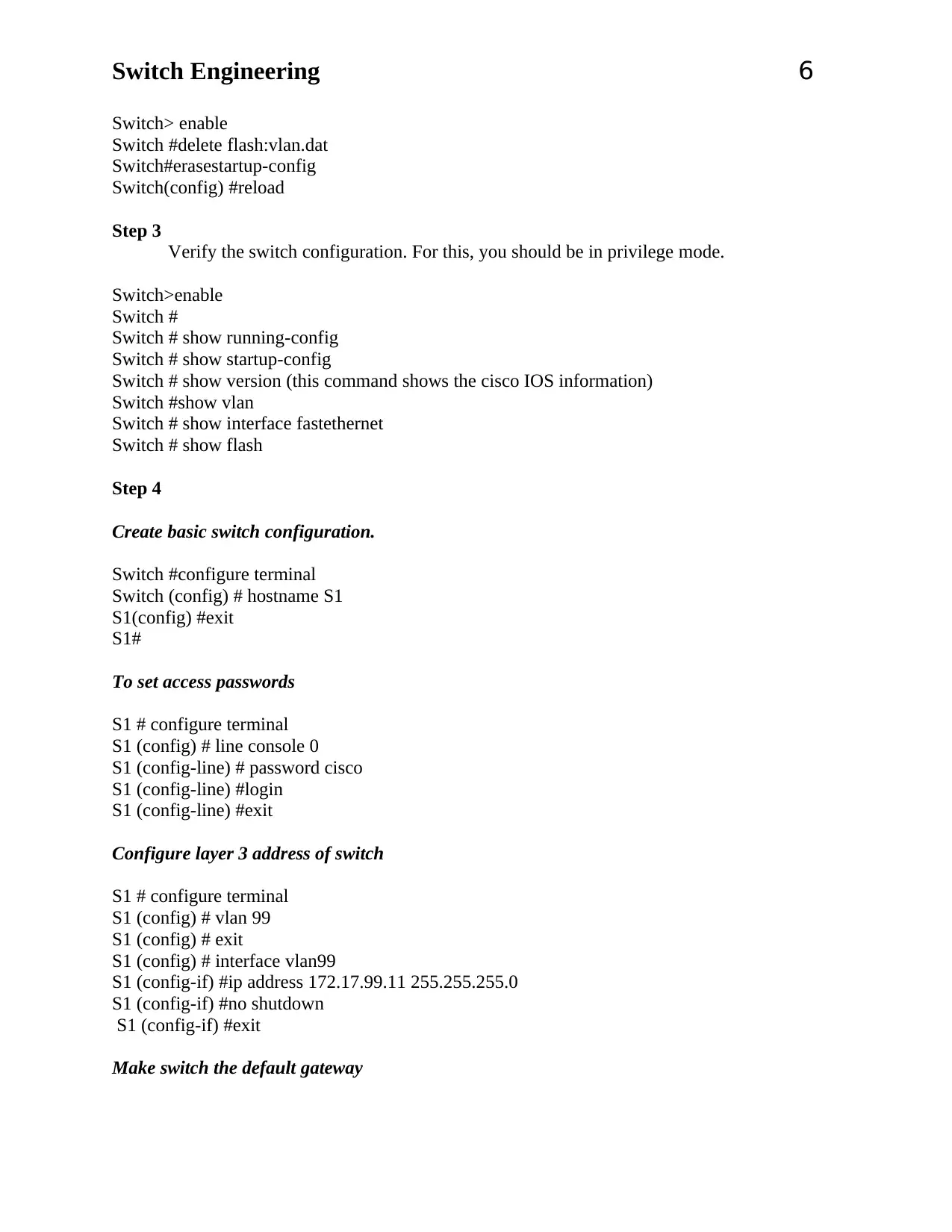
3. Taking an example of Cisco Switch, demonstrate the basic
Switch
Topology
Step 1
The network has to be cabled as shown in the topology diagram. The console connection
should be linked to a display unit.
Step 2
Clear the switch configuration.
Packet switching
During packet switching, data is broken into small packets. Long messages can be broken into a
series of smaller packets. Each packet is built with control information. Control information is
necessary for routing. Based on the routing information, packets are sent from one source and
stored in the destination (the packets cross a series of nodes in between). Major benefits in using
packet switching would be as follows:
1) Better data rate conversion
2) Line efficiency
3) Packets can be transferred even when the network is very busy
4) Priorities can be used to define packets
3. Taking an example of Cisco Switch, demonstrate the basic
Switch
Topology
Step 1
The network has to be cabled as shown in the topology diagram. The console connection
should be linked to a display unit.
Step 2
Clear the switch configuration.
Switch Engineering 6
Switch> enable
Switch #delete flash:vlan.dat
Switch#erasestartup-config
Switch(config) #reload
Step 3
Verify the switch configuration. For this, you should be in privilege mode.
Switch>enable
Switch #
Switch # show running-config
Switch # show startup-config
Switch # show version (this command shows the cisco IOS information)
Switch #show vlan
Switch # show interface fastethernet
Switch # show flash
Step 4
Create basic switch configuration.
Switch #configure terminal
Switch (config) # hostname S1
S1(config) #exit
S1#
To set access passwords
S1 # configure terminal
S1 (config) # line console 0
S1 (config-line) # password cisco
S1 (config-line) #login
S1 (config-line) #exit
Configure layer 3 address of switch
S1 # configure terminal
S1 (config) # vlan 99
S1 (config) # exit
S1 (config) # interface vlan99
S1 (config-if) #ip address 172.17.99.11 255.255.255.0
S1 (config-if) #no shutdown
S1 (config-if) #exit
Make switch the default gateway
⊘ This is a preview!⊘
Do you want full access?
Subscribe today to unlock all pages.
Trusted by 1+ million students worldwide
Switch Engineering 7
S1(config)#ip default-gateway 172.17.99.1
S1(config)#exit
Configure the duplex settings and port speed
S1#configure terminal
S1(config)#interface fastethernet 0/18
S1(config-if)#speed 100
S1(config-if)#duplex full
S1(config-if)#end
Saving configuration
S1#copy running-configstartup-config
Setting up MAC address
S1(config)#mac-address-table static 00e0.2917.1884 interface fastethernet 0/18 vlan 99
List the port security options.
S1# configure terminal
S1(config)#interface fastethernet 0/18
S1(config-if)#switchport port-security ?
aging Port-security aging commands
mac-address Secure mac address
maximum Max secure addresses
violation Security violation mode
S1(config-if)#switchport port-security
Configure port security on an access port.
S1(config-if)#switchport mode access
S1(config-if)#switchport port-security
S1(config-if)#switchport port-security maximum 2
S1(config-if)#switchport port-security mac-address sticky
S1(config-if)#switchport port-security violation protect
S1(config-if)#exit
Verify the results.
S1#show port-security
Modify the port security settings on a port.
Paraphrase This Document
Need a fresh take? Get an instant paraphrase of this document with our AI Paraphraser
Switch Engineering 8
S1(config-if)#switchport port-security maximum 1
S1(config-if)#switchport port-security violation shutdown
Verify the results.
S1#show port-security
Task 2 – Investigate and design Switching Security
1. Examine the Network Security Concepts.
Network devices like gateways, routers, hubs, firewalls and switches create an organizational
network (Pearson Education, 2017). Securing these components of the network is very important
Switch Engineering 9
for protecting all forms of incoming and outgoing communications. The network is prone to
many security risks. Here are few common and essential network security concepts.
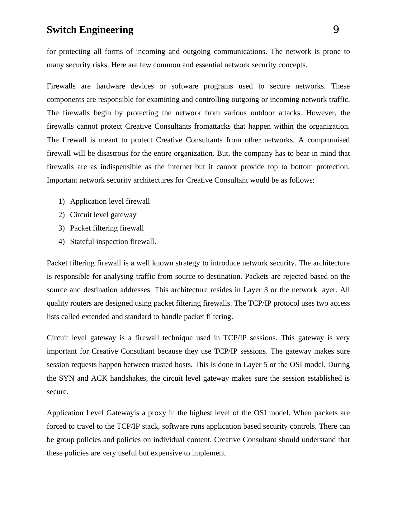
Firewalls are hardware devices or software programs used to secure networks. These
components are responsible for examining and controlling outgoing or incoming network traffic.
The firewalls begin by protecting the network from various outdoor attacks. However, the
firewalls cannot protect Creative Consultants fromattacks that happen within the organization.
The firewall is meant to protect Creative Consultants from other networks. A compromised
firewall will be disastrous for the entire organization. But, the company has to bear in mind that
firewalls are as indispensible as the internet but it cannot provide top to bottom protection.
Important network security architectures for Creative Consultant would be as follows:
1) Application level firewall
2) Circuit level gateway
3) Packet filtering firewall
4) Stateful inspection firewall.
Packet filtering firewall is a well known strategy to introduce network security. The architecture
is responsible for analysing traffic from source to destination. Packets are rejected based on the
source and destination addresses. This architecture resides in Layer 3 or the network layer. All
quality routers are designed using packet filtering firewalls. The TCP/IP protocol uses two access
lists called extended and standard to handle packet filtering.
Circuit level gateway is a firewall technique used in TCP/IP sessions. This gateway is very
important for Creative Consultant because they use TCP/IP sessions. The gateway makes sure
session requests happen between trusted hosts. This is done in Layer 5 or the OSI model. During
the SYN and ACK handshakes, the circuit level gateway makes sure the session established is
secure.
Application Level Gatewayis a proxy in the highest level of the OSI model. When packets are
forced to travel to the TCP/IP stack, software runs application based security controls. There can
be group policies and policies on individual content. Creative Consultant should understand that
these policies are very useful but expensive to implement.
for protecting all forms of incoming and outgoing communications. The network is prone to
many security risks. Here are few common and essential network security concepts.
Firewalls are hardware devices or software programs used to secure networks. These
components are responsible for examining and controlling outgoing or incoming network traffic.
The firewalls begin by protecting the network from various outdoor attacks. However, the
firewalls cannot protect Creative Consultants fromattacks that happen within the organization.
The firewall is meant to protect Creative Consultants from other networks. A compromised
firewall will be disastrous for the entire organization. But, the company has to bear in mind that
firewalls are as indispensible as the internet but it cannot provide top to bottom protection.
Important network security architectures for Creative Consultant would be as follows:
1) Application level firewall
2) Circuit level gateway
3) Packet filtering firewall
4) Stateful inspection firewall.
Packet filtering firewall is a well known strategy to introduce network security. The architecture
is responsible for analysing traffic from source to destination. Packets are rejected based on the
source and destination addresses. This architecture resides in Layer 3 or the network layer. All
quality routers are designed using packet filtering firewalls. The TCP/IP protocol uses two access
lists called extended and standard to handle packet filtering.
Circuit level gateway is a firewall technique used in TCP/IP sessions. This gateway is very
important for Creative Consultant because they use TCP/IP sessions. The gateway makes sure
session requests happen between trusted hosts. This is done in Layer 5 or the OSI model. During
the SYN and ACK handshakes, the circuit level gateway makes sure the session established is
secure.
Application Level Gatewayis a proxy in the highest level of the OSI model. When packets are
forced to travel to the TCP/IP stack, software runs application based security controls. There can
be group policies and policies on individual content. Creative Consultant should understand that
these policies are very useful but expensive to implement.
⊘ This is a preview!⊘
Do you want full access?
Subscribe today to unlock all pages.
Trusted by 1+ million students worldwide
Switch Engineering 10
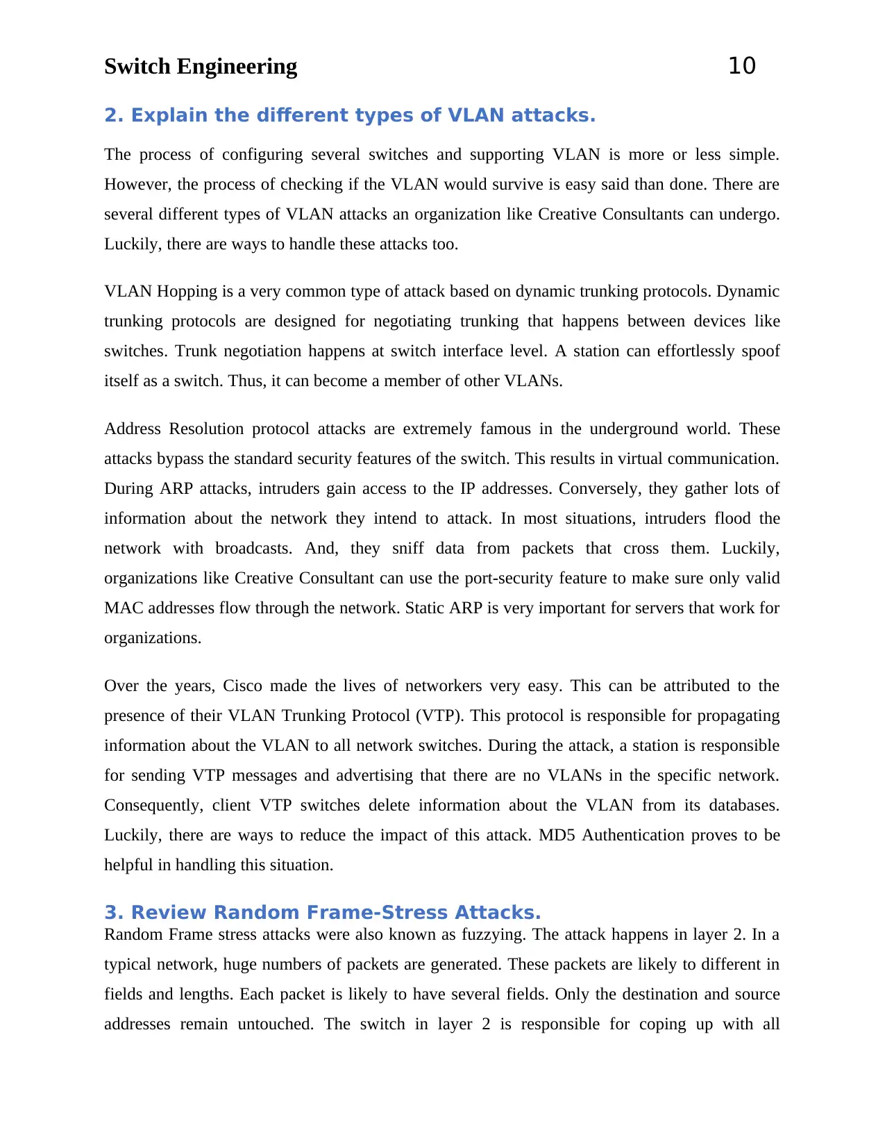
2. Explain the different types of VLAN attacks.
The process of configuring several switches and supporting VLAN is more or less simple.
However, the process of checking if the VLAN would survive is easy said than done. There are
several different types of VLAN attacks an organization like Creative Consultants can undergo.
Luckily, there are ways to handle these attacks too.
VLAN Hopping is a very common type of attack based on dynamic trunking protocols. Dynamic
trunking protocols are designed for negotiating trunking that happens between devices like
switches. Trunk negotiation happens at switch interface level. A station can effortlessly spoof
itself as a switch. Thus, it can become a member of other VLANs.
Address Resolution protocol attacks are extremely famous in the underground world. These
attacks bypass the standard security features of the switch. This results in virtual communication.
During ARP attacks, intruders gain access to the IP addresses. Conversely, they gather lots of
information about the network they intend to attack. In most situations, intruders flood the
network with broadcasts. And, they sniff data from packets that cross them. Luckily,
organizations like Creative Consultant can use the port-security feature to make sure only valid
MAC addresses flow through the network. Static ARP is very important for servers that work for
organizations.
Over the years, Cisco made the lives of networkers very easy. This can be attributed to the
presence of their VLAN Trunking Protocol (VTP). This protocol is responsible for propagating
information about the VLAN to all network switches. During the attack, a station is responsible
for sending VTP messages and advertising that there are no VLANs in the specific network.
Consequently, client VTP switches delete information about the VLAN from its databases.
Luckily, there are ways to reduce the impact of this attack. MD5 Authentication proves to be
helpful in handling this situation.
3. Review Random Frame-Stress Attacks.
Random Frame stress attacks were also known as fuzzying. The attack happens in layer 2. In a
typical network, huge numbers of packets are generated. These packets are likely to different in
fields and lengths. Each packet is likely to have several fields. Only the destination and source
addresses remain untouched. The switch in layer 2 is responsible for coping up with all
Paraphrase This Document
Need a fresh take? Get an instant paraphrase of this document with our AI Paraphraser
Switch Engineering 11
unexpected or meaningless fields in the packets. Random frame stress attacks are brute force
attacks. Several fields in the packet are likely to be affected by this attack. The ultimate aim of
such an attack is to trigger VLAN leakage (packages are seen on different VLANs apart from the
one they are meant to be in). Luckily, there are few techniques to prevent random frame stress
attacks. For example, the switch responsible for receiving packets from the source should
prevent frames that are seen on different ports apart from the receiving VLAN. Unfortunately,
there are no configuration settings to prevent this attack. The switch used by organizations
should be inherently robust to prevent such attacks. Another way to prevent random frame stress
attacks is by isolating hosts. Hosts in Layer 2 can be isolated easily, especially in private VLAN
settings. These hosts should then be protected from malicious or unwanted traffic that comes
from untrustworthy devices. Small communities of trusting devices can be established in Layer 2
to make sure only devices that are supposed to communicate with one another. This is a step
taken by many organizations to make sure random frame stress attacks don’t happen!
Switch Engineering 12
Task 3 – Understand the concepts underlying Ethernet
Switching Network Design
1. Analyse the Ethernet Switching.
Ethernet switches are designed to link various Ethernet devices together. The link is established
using Ethernet frames (Fairhurst, 2012). By moving Ethernet frames through various switch
ports, links can be created. Also, these switch ports form larger Ethernet networks. Ethernet
switching involves a linking function that bridges Ethernet frames between several Ethernet
segments. The MAC address is necessary to copy Ethernet frames from one port to another
switch port. Very first Ethernet bridging was defined in 802.1D IEEE standard for LAN and
MAN: media access control (MAC) bridges.
The first and foremost Ethernet bridge had two port devices. The two port device was capable of
linking coaxial cables. In the beginning, Ethernet supported only coaxial cables. With time,
Ethernet improved to support several ports, hubs and central connection points. Since early
1980s (when Ethernet was first designed) things have changed drastically. Today, Ethernet
switching involves hundreds of switch connections within a single building or across several
networks.
The ultimate operation of Ethernet switching is to move critical data between computers. To
accomplish the task, a network program is required to organize data into frames. Frames travel in
the Ethernet network. The frame has a data field to represent data that can be carried between
computers. By definition, frames are arbitrary sequences of information whose format is clearly
defined. The frame has a destination address and a source address. The frames are defined in the
data link layer or layer 2 in the OSI model. Ethernet switching happens in a transparent fashion.
This means, devices in the network will not go through any changes. When a switch is connected
to a Ethernet device, the frames are not changed in any way. The switch knows how to begin
work without any configuration. This is why Ethernet switching is deemed as transparent. IEEE
802.1D bridging standards are used by Ethernet switch for transmitting frames between various
switch ports. Traffic forwarding rules are based on address learning. The forwarding decisions
are made based on the MAC address in the local LAN settings (including the Ethernet). To
engage in Ethernet forwarding, the switch has to be aware of stations in the network that can
receive and send frames.
⊘ This is a preview!⊘
Do you want full access?
Subscribe today to unlock all pages.
Trusted by 1+ million students worldwide
1 out of 18
Related Documents


Your All-in-One AI-Powered Toolkit for Academic Success.
+13062052269
info@desklib.com
Available 24*7 on WhatsApp / Email
![[object Object]](/_next/static/media/star-bottom.7253800d.svg)
Unlock your academic potential
Copyright © 2020–2026 A2Z Services. All Rights Reserved. Developed and managed by ZUCOL.