Comprehensive Report on LAN Technologies, Hardware and QoS Management
VerifiedAdded on 2020/01/28
|50
|6692
|117
Report
AI Summary
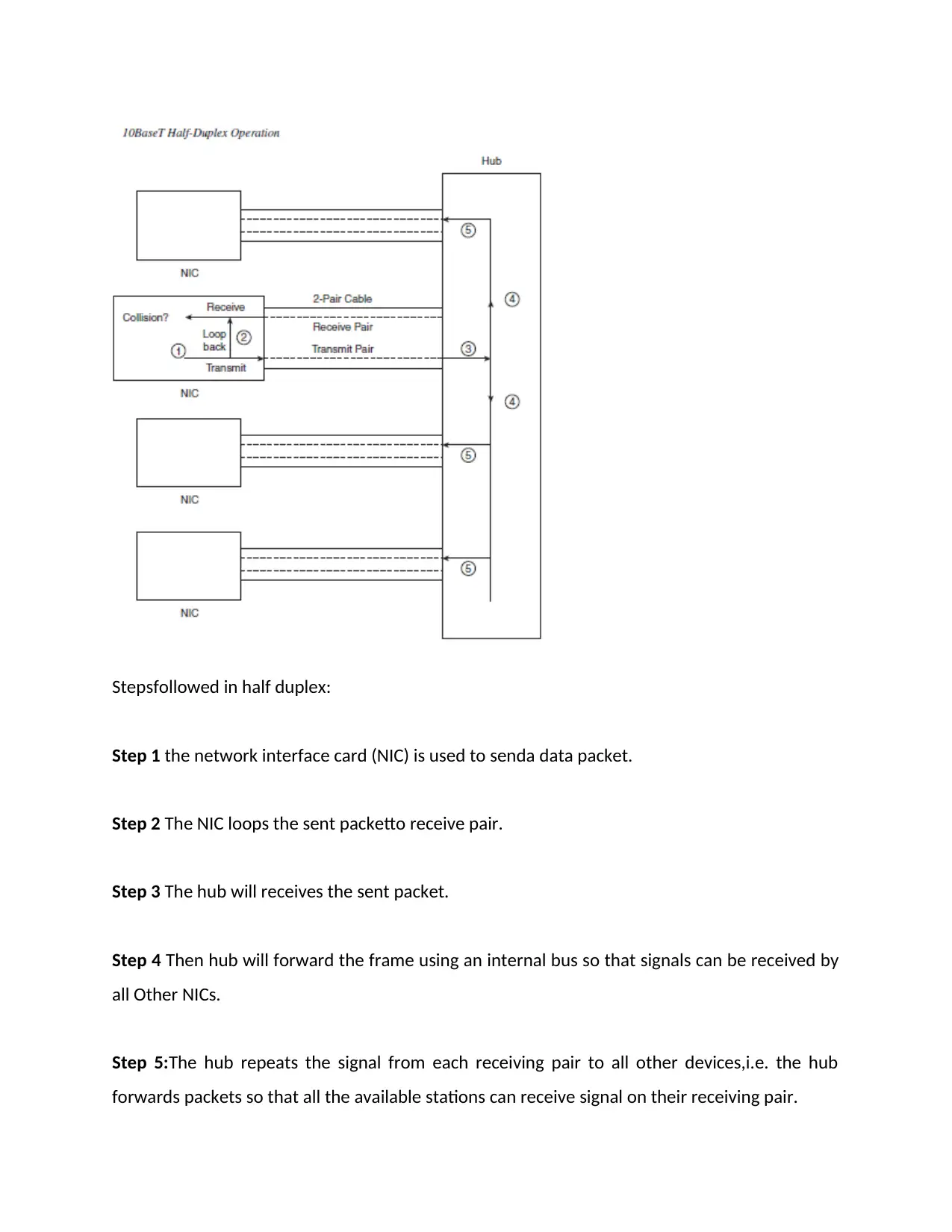
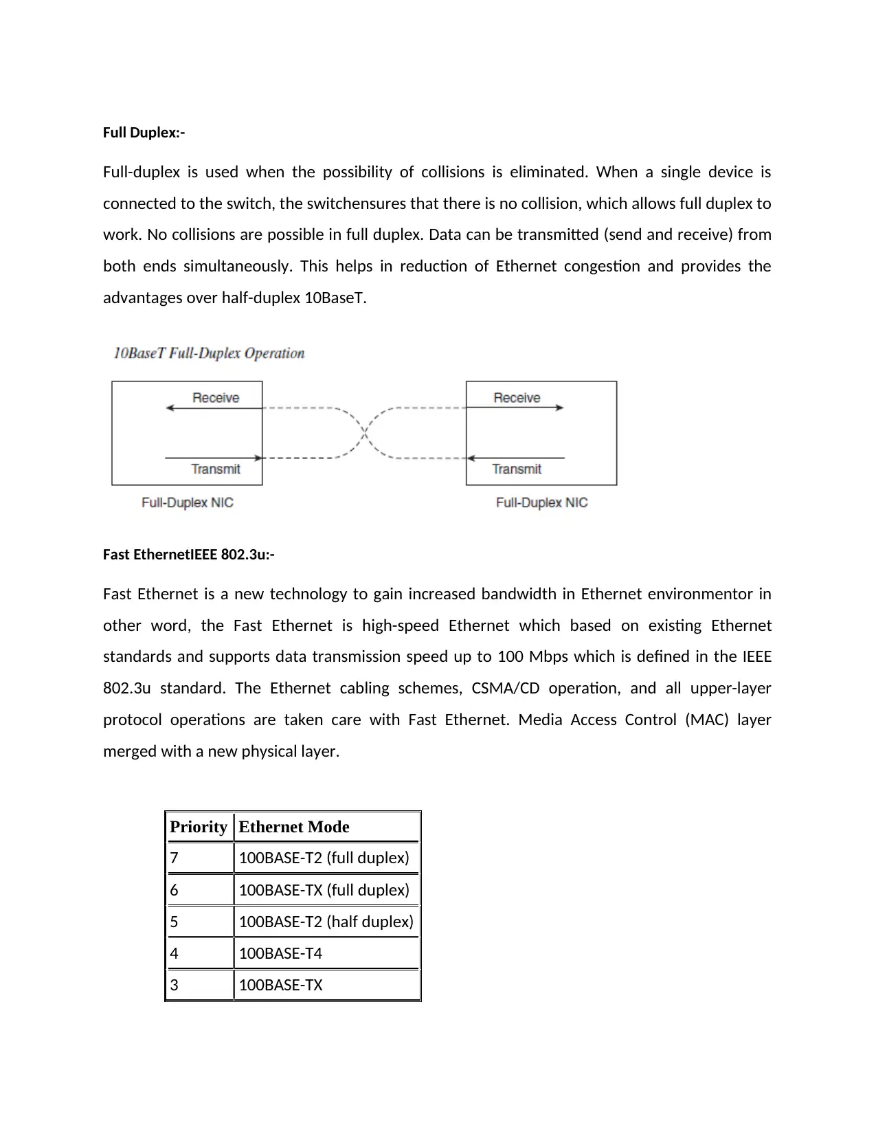
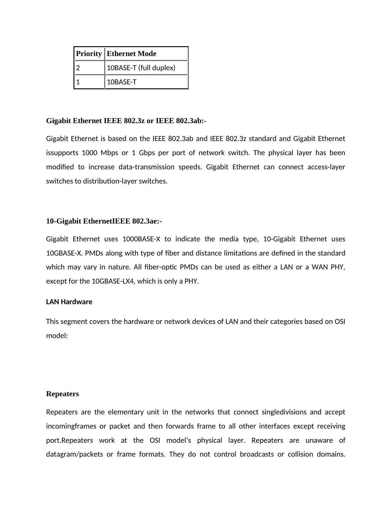
This report provides a comprehensive analysis of LAN technologies, focusing on their role in enhancing organizational performance. It details various LAN technologies such as Ethernet, Fast Ethernet, and Gigabit Ethernet, along with their functionalities and applications. The report explores LAN hardware, including file servers, hubs, bridges, switches, routers, and firewalls, categorizing these devices based on the OSI model. It delves into the significance of Quality of Service (QoS) and bandwidth management, explaining their importance with examples. Furthermore, it covers topics such as IP address management, VLANs, and network topologies like bus, star, ring, mesh, tree, and hybrid, offering insights into their configurations and characteristics. The report also examines the role of switches, including their modes of operation and broadcast domains. Overall, the report provides a detailed overview of LAN technologies, network devices, and their impact on network performance and security.
Contribute Materials
Your contribution can guide someone’s learning journey. Share your
documents today.

Contents
Introduction.................................................................................................................................................2
TASK 1..........................................................................................................................................................2
LAN Hardware.....................................................................................................................................7
TASK 2........................................................................................................................................................18
TASK 3........................................................................................................................................................21
IP Address and VLSM.............................................................................................................................24
TASK 4........................................................................................................................................................25
TASK 5........................................................................................................................................................27
REFERENCES..............................................................................................................................................42
Secure Best Marks with AI Grader
Need help grading? Try our AI Grader for instant feedback on your assignments.

Introduction
The report is prepared to analyze the use of LAN technologies and their role to increase the
performance of the organization. The project provides detailsof LAN and related techniques
and models to overcome security related issues. It will also explain LAN hardware such as file
servers, hubs, bridges, switches, routers, multilayer switches, voice gateways, firewalls, and
other devices. Computers in LAN are getting connected with a cable through Ethernet, Fast
Ethernet and Gig Ethernet or other media.
Security is one of the main aspects of any network because of data importance to an
organization. This course will help to learn router configuration, packet filter, troubleshooting
network, test network performance etc. This course will also help to get the understanding of
an IP address/pool management, VLAN, STP , VTP or monitoring tool for a network.
TASK 1
1.1 Evaluate various LAN technologies available in the market. Describe the technologies in
relation with scenario above.
LAN:In an enterprise network computers are getting connected in the same geographic area or
location known as LAN. An organization typically owns the entire campus network and the

physical wiring. Campus networks commonly consist of Ethernet, 802.11 wireless LANs, higher-
speed Fast Ethernet, Fast Ether Channel, and Gigabit Ethernet LANs.
Institute of Electrical and Electronics Engineers (IEEE) Ethernet (802.3):-
Ethernet is a LAN technology based on the 802.3 standard of IEEE(Institute of Electrical and
Electronics Engineers) and offers a bandwidth of 10 Mbps between end users or PC, in other
words, LAN Technology is used to provide connectivity between PCsusing Ethernet technology
and committed speed is 10 Mbps between every end user. Switched Ethernet can eliminate the
possibility of collisions. In full-duplex modedata can be transmitted or received simultaneously,
hence Full-duplex mode increases network performance with throughput of 10 Mbps in each
direction.

Half-Duplex:-
Half duplex is a feature of LAN technology which is being used by many devices such as HUB or
repeater. These hubs are basically multiport repeaters which extends the bus topology concept
of 10Base2 and 10Base5 by regenerating the same signal sent by the original device. Therefore,
collisions can still occur and CSMA/CD access rules are used to avoid collisions. Below figure
outlines the operation of half-duplex 10BaseT withhubs:
Secure Best Marks with AI Grader
Need help grading? Try our AI Grader for instant feedback on your assignments.

Stepsfollowed in half duplex:
Step 1 the network interface card (NIC) is used to senda data packet.
Step 2 The NIC loops the sent packetto receive pair.
Step 3 The hub will receives the sent packet.
Step 4 Then hub will forward the frame using an internal bus so that signals can be received by
all Other NICs.
Step 5:The hub repeats the signal from each receiving pair to all other devices,i.e. the hub
forwards packets so that all the available stations can receive signal on their receiving pair.

Full Duplex:-
Full-duplex is used when the possibility of collisions is eliminated. When a single device is
connected to the switch, the switchensures that there is no collision, which allows full duplex to
work. No collisions are possible in full duplex. Data can be transmitted (send and receive) from
both ends simultaneously. This helps in reduction of Ethernet congestion and provides the
advantages over half-duplex 10BaseT.
Fast EthernetIEEE 802.3u:-
Fast Ethernet is a new technology to gain increased bandwidth in Ethernet environmentor in
other word, the Fast Ethernet is high-speed Ethernet which based on existing Ethernet
standards and supports data transmission speed up to 100 Mbps which is defined in the IEEE
802.3u standard. The Ethernet cabling schemes, CSMA/CD operation, and all upper-layer
protocol operations are taken care with Fast Ethernet. Media Access Control (MAC) layer
merged with a new physical layer.
Priority Ethernet Mode
7 100BASE-T2 (full duplex)
6 100BASE-TX (full duplex)
5 100BASE-T2 (half duplex)
4 100BASE-T4
3 100BASE-TX

Priority Ethernet Mode
2 10BASE-T (full duplex)
1 10BASE-T
Gigabit Ethernet IEEE 802.3z or IEEE 802.3ab:-
Gigabit Ethernet is based on the IEEE 802.3ab and IEEE 802.3z standard and Gigabit Ethernet
issupports 1000 Mbps or 1 Gbps per port of network switch. The physical layer has been
modified to increase data-transmission speeds. Gigabit Ethernet can connect access-layer
switches to distribution-layer switches.
10-Gigabit EthernetIEEE 802.3ae:-
Gigabit Ethernet uses 1000BASE-X to indicate the media type, 10-Gigabit Ethernet uses
10GBASE-X. PMDs along with type of fiber and distance limitations are defined in the standard
which may vary in nature. All fiber-optic PMDs can be used as either a LAN or a WAN PHY,
except for the 10GBASE-LX4, which is only a PHY.
LAN Hardware
This segment covers the hardware or network devices of LAN and their categories based on OSI
model:
Repeaters
Repeaters are the elementary unit in the networks that connect singledivisions and accept
incomingframes or packet and then forwards frame to all other interfaces except receiving
port.Repeaters work at the OSI model’s physical layer. Repeaters are unaware of
datagram/packets or frame formats. They do not control broadcasts or collision domains.
Paraphrase This Document
Need a fresh take? Get an instant paraphrase of this document with our AI Paraphraser

Repeaters are protocol-transparent becauseof unawareness about upper-layer protocols such
as IP, Internetwork Packet Exchange (IPX), etc.
HUB:-
Hub is basic unit in LAN technology and they works on physical layer of OSI model. Hubs have
more ports than basic repeaters.
Bridges:-
Bridges are store-and-forward devices which store the entire frame or datagram and verify the
cyclicredundancy check (CRC) before forwarding the same. If the bridges detect a CRC error in
frame or datagram, it discards the same. Bridges are protocol-transparent i.e. unaware of the
upper-layer protocols such as IP,IPX etc.
Bridges implement Spanning Tree Protocol (STP) to build a loop-free network. Bridges
communicate with each other and exchange information. Bridges select a root bridge and then
implement STP.

Switches:-
Switch is a multiport transparent bridge. A switch port can work as its own Ethernet LAN
segment which is isolated from the other switch ports. Frame/packet forwarding uses MAC
address which is contained in each frame, without which switch cannot forward a frame.
Switches are integrated circuits or intelligent LAN device to reduce the latency in LAN segment
or environment. Switches can run in cut-through modein which it will not wait for the complete
frame or datagram to enter its buffer. Instead of this it starts forwarding the frame as soon
asdestination MAC address received. By using this mode of operation probability of errors being
forwarded in the networkincreases because it forwards the frame without entire frame is
buffered and checked for errors.
Collision-domain and broadcast-domain characteristicsof switches and bridges are exactlysame.
Eachport on a switch is a separate collision domain. All ports in a switch are in the
samebroadcast domain by default which can be changed by assigning different VLANs.

Broadcasts:-
Broadcasts are specialized frames or datagram packets that are destined for all devices on an
Ethernet network. Broadcasts produceMAC address of FF-FF-FF-FF-FF-FF. It is the highest
number allowed in the 48-bit schema of MAC addresses. In the binary, all 48 bits are set to 1.
Multicasts:-
Multicasts are specialized broadcasts and used by higher layer protocols to manage traffic to
more than one destinations, while a broadcast sends to all destinations. Application layer
multicasts start with 01-00-5E prefix and rest of the digits are appended by application layer
protocol handling the multicast. Other Layer-2 multicast addresses do not have the prefix of 01-
00-5E. Higher layer protocols, such as IGMP (Internet Group Messaging Protocol), are being
used by switches to identify traffic pattern and forward only multicast.
Multilayer Switching:-
Multilayer switching performed at Layer 3 and Layer 4 in switches. Layer 3 (Catalyst family of
switches) does the caching of traffic based on IP addresses while Layer-4 switches doe the
caching based on source and destination addresses along with source and destination ports.
Secure Best Marks with AI Grader
Need help grading? Try our AI Grader for instant feedback on your assignments.

Router:-
Logical addressing in network can be achieved with routers because network layer (Layer 3)
address can be used to uniquely identify a device in the network. Actual data/frame forwarding
happens at Layer 2 byusing address of devices. A method is used to associate a device's MAC
address (data link layer) with its IP address (network layer). A router has addresses from both
layers assigned to each of its interfaces which are connected to network.
LAN Topologies:-
Logical LAN topologies can be configured with equipment’s such as router or switch. There are
mainly 6 types of topologies:
1) Bus
2) Star
3) Ring
4) Mesh
5) Tree
6) Hybrid
1) Bus:In this topology, each node is connected to single cable and signals from each node
travels in both the direction. This is economical to setup. Bus topology is of two types:
linear and distributed. Both are same in nature but distributed uses common
transmission medium which has more than 2 end points.

2) Star: In this topology one node is connected with all other nodes and this node act as
server and others as client. These are of two types: extended star and distributed star.
In distributed star, nodes are connected in chain with no central or top level connection
point.
3) Ring:In this topology nods are connected in circular fashion in which data travels from
one node to other until it reaches to its destination. Data travels in one direction. All the
nodes work as server and repeat the signals.Dis-advantage of this is that each node is
critical and data transmission will fail if one node stops working.
4) Mesh:In this topology each node is directly connected with another node. It is
categorized in two types: fully connected network and partially connected network.In
fully-connected all the nodes are inter-connected directly with each other.Fully
connected network is practically impossible for large network because it will be complex
to manage and implementation cost will also be high. Partially connected network is
inexpensive.

5) Tree:This topology has tree like structure i.e. it will have one root node, intermediate
nodes and the branch nodes. The outermost nodes known as leaves. There must be 3
levels at least in the hierarchy to form a tree else it will work as star topology. Fault
identification is easy and it is easy to manage. It supports point to point connection of
the nodes.
6) Hybrid:This topology is combination of any two or more of the above defied topology
but both connected network must be of different topology. Common combinations are
star-ring topology and star bus topology.
1.2 What do you understand by quality of service (QoS) and bandwidth management? Evaluate and
analyse with examples why do you think it is important to perform QoS and Bandwidth Management?
Quality of service QoS :-
Quality of service (QoS) is defined as providing betterexperience to users. The motivation
behind QoS is to allow network and user-critical data to have consistent and reliable access to
the network. QoS helps with management of latency and bandwidth on the network. QoS
objectives are to provide reliable and available resources for applications and services on the
network. In other words QoS should maintain better data transfer in the network. Most
networks today are implementing QoS for these reasons. Customers are looking for cheaper
alternate like increasing bandwidth on the network to support the various services they are
supporting. However, Increase in bandwidth is the not only option to improve QoS. Some
applications are delay sensitive and require special handling on the network device itself.
There are two types of QoS architectures are available: first is Integrated Services (IntServ) and
second is Differentiated Services (DiffServ).
Paraphrase This Document
Need a fresh take? Get an instant paraphrase of this document with our AI Paraphraser

Integrated Services is designed to provide guaranteed resources to applications from the
available network resources. For example, a network application via Resource Reservation
Protocol (RSVP), requests specific bandwidth from the network for a given flow. RSVP will visit
each network hop toward the destination IP address and will attempt to allocate network
bandwidth resources. If the results are positive, the application can send its traffic on the
network. RSVP can help in allocation of resources for delay-sensitive applications along with
this it can provide the traditional best-effort service also. The idea behind architecture is that if
specific application traffic flow requirements are met, the impact on network performance can
be minimized.
DiffServdefined traffic have a higher priority over other traffic in the network. For example, the
more network resources can be allocated for voice traffic instead of data traffic. DiffServdo not
support an all-or-none mechanism. No admission controls mechanism exists in DiffServbut it
exists in IntServ. Traffic in network is being handled by each network device based on their
configuration. DiffServarchitecture is mainly used because it is more scalable and flexible than
IntServ.
There are five steps involved in QoS operational model:
1. Classification
2. Input scheduling
3. Marking and policing
4. Marking
5. Output scheduling
Classification
Classification is used to distinguish one incoming frame from another so that it can be
forwardedthrough the switch. Switch's port is programmed to be untrusted so that it can
receive any incoming frame and can reset CoS value to 0. The default CoS value is changeable,
and a new CoS value can be assigned to that frame which is configured on that port. If the port

is configured to be trusted, CoS value will not be changed and it will remain same whatever
value received with frame. An entry port can be configured with the following options:
Input scheduling
Input scheduling is used to handle the frame post frame arrived at the ingress port which has
been configured as trusted port. Input scheduling assigns incoming frames to queues. When
trust CoS is not configured, incoming frames bypasses the Receive threshold queue and will
forward directly to the switching engine. Each queue has its own drop threshold level i.e.
frames will get dropped once the threshold value of queue is reached.

The number of queues and drop threshold values are configurable and depends on underlying
hardware that is used in network. There are two defined queues:
rx-(1q4t) – 1 Queue with 4 drop threshold
tx-(2q2t) - 2 Queue with 2 drop threshold
Newer line cards have 1p1q4t which is 1 priority queue, 1 normal queue, with 4 drop threshold
queues.
Each of these thresholds are used to drop incoming packets. Packet identification which should
be dropped depends on CoS setting and the amount of buffer used.
Marking and policing
It is used to help the switching engine to appropriately service the frame. The internal DSCP
value isidentified from DSCP or IP precedence value of the packet at Layer 3, CoS value of frame
at Layer 2, or from a user-defined access list. Switching engine first marks the traffic and then
checks for policing. It also monitors the bandwidth utilization i.e. policing areused to control
bandwidth use. The policing mechanism imposes upper limit on the amount of bandwidth that
can be utilized. Once the bandwidth utilization crosses the defined limit, traffic will either be
dropped or its priority will be marked down.
Marking
The switching engine forwards the traffic to the outport. The internal DSCP values are assigned
to incoming traffic at the switching engine which can contain respectiveCoS or DSCP/IP
precedence values.
Secure Best Marks with AI Grader
Need help grading? Try our AI Grader for instant feedback on your assignments.

Output scheduling
After marking, the traffic is forwarded to the appropriate transmit queue on the egress port.
The number of queues and drop threshold varies based on used hardware. The queue on the
egress port isused to service higher priority traffic first. Congestion avoidance on Cisco switches
is used to minimize dropping of critical traffic.
1.3 Discuss LAN concerns in terms of network security, availability and performance? explain how a
Hierarchical Network Design can improve on availability, security, scalability and performance
Hierarchical Network Design :-

A hierarchical approach to network design enables network designers to logically create a
network by defining and using different layers of devices used in network which results in a
secure, efficient, scalable, manageable, high performance and high available network.
Hierarchical design facilitates changes in a network design while modularity allows designingin
such manner so that it can be replicated as the network grows. Changes in network
architecture will tend to impact a large number of systems.
Small structured network with easy-to-understand elements improves fault isolation. Network
managers can easily understand the transition points defined in the network, which helps them
to identify failure points.To control the impact of routing-protocol processing and bandwidth
consumption, modular hierarchical topologies must be used such as Open Shortest Path First
(OSPF).
Hierarchical network design facilitates route summarization which helps EIGRP and all other
routing protocols. Route summarization helps in reducing routing-protocol overhead on links in
the network. This also reduces routing-protocol processing within the routers.
Access Layer:-
The access layer offers user access to local segments on the network. In other word the access
layer is providing low cost per switch port, High port density, Scalable uplinks to higher
layers,redundancy using multiple uplinks. They use User access functions such as VLAN
membership, traffic and protocol filtering, and QoS. The access layer is categorized by switched
and shared-bandwidth LAN segments in a campus environment.
Distribution Layer

The distribution layer provides interconnection between access and corelayers. Devices in this
layer provides throughput for packet handling, Security and policy-based connectivity functions
using access lists or packet filters.
Core Layer
Core layer delivers connectivity of all distribution layer devices. The core layer also known as
backbone of network. It provides very high throughput at Layer 2 or Layer 3. It provide less
costly services and avoids unnecessary packet manipulations. It uses redundancy to support
high availability.
TASK 2
2.1 Design network infrastructure to fulfill the requirement of above scenario, including the diagram of
the network infrastructure, and all devices (ie. Switches, routers, cables, etc.)?
Paraphrase This Document
Need a fresh take? Get an instant paraphrase of this document with our AI Paraphraser

To implement the given scenario, we have used following network devices:
Router:-
As per our scenario we are using 5 Routers for 5 branches (Edinburgh, Birmingham, Liverpool,
Manchester and Glasgow) and one new head office in Central London. All router exchange
information about destination networks using 3 routing protocols (Enhanced Interior Gateway
Routing Protocol (EIGRP), Open Shortest Path First (OSPF) and Border Gateway Protocol (BGP).
Routers use routing protocols to build a list of destination networks to identify the best routes
to reach those destinations.
Switches :-We need these type of switches for connectivity as per our network scenario
Core Switch :-Router are connected to core switch
Distribution switches :-Core switch get connected to distribution switch
Access Switches :-All end device get connected to access switch
Customer Service Switch:-As per given scenario 5 device or PCs are required, for that we have
installed 24 port switch in Customer service

Accounts/Finance Switch:-This department will have 34 PC and a network printer and will be
accessed by those who are working in finance department
Library Switch:-With 200 systems, the library will be divided in two rooms with three 48 port
switch, each of which will contain 100 devices including a network printer. They should also be
able to use printer available in network from these machines.
2.2 Critically evaluate the suitability of network components in your design in terms of Security ,
Scalability and Availability
2.2.1 Security
Every organization has a security policy in place to protect data.It can begin with applying policy
to these documents and its rules to their particular environment. Organizations security policies
create a roadmap that helps organizations to implement the correct security appliances,
mechanisms, and control that satisfy their security needs. The organization will also quickly
begin to find the weaknesses in their security mechanism using the process of identifying
important resources and associated policies. This documentation is getting changed over period
of time as per changes in computing and physical environments. These changes should be
expected and accepted as normal security policy maintenance. The underlying network
provides an perfect place to implement security solutions. The center of these secure network
solutions includes the Adaptive Security Appliances (ASA), Integrated Services Routers (ISR),
and Cisco Catalyst switches that have integrated security embedded in them. These are highly
intelligent network security devices with many built-in security features that provide a
framework for incorporating security in the network.
2.2.2 Scalability
The scalability is necessary in technology as well as in our organizations or business settings.
The basic idea is to provide uninterrupted services to customer or organizations and to accept
increased volume without any outage and downtime. In other words it can refer to the ability
of a system to increase its total throughput with additional resources when load on system

increases. For instance we are using copper coaxial cable and now we need to upgrade it to UTP
cable.
2.2.3 Availability
Availability is something when system or services are available for use to end user. E.g. uptime
or availability for an electrical infrastructure is measured by counting the days or hour or
minutes, electricity was made available in Data Center so that user services are uninterrupted.
TASK 3
3.1 Draw a complete LAN design including servers, connecting devices, workstations,
peripherals, etc. for the above scenario. Please include the configuration scripts in the
appendix.
Secure Best Marks with AI Grader
Need help grading? Try our AI Grader for instant feedback on your assignments.

With the help of cisco packet tracer, we have designed our network scenario and we are
explaining this below mention scenario step by step which we design for new head office in
Central London .
Frist we have installed router that is connected with service provider router and after that we
configured core switch and implemented all LAN technology
1. First of all we are going to connect core switch with access switch and distribution
switch , at access switch all end user are connected and all server and critical device
with distribution switch .
2. Configure host name of core switch router and all network device
3. We create new 3 VLAN (Finance Accounts, Library department, Customer Service
department VLAN ) and server vlan in core switch
4. After that we configure VTP domain ( virtual trunking protocol ) in core switch
5. We onfigure STP in core switch so we can protract for network loop or loop free
network

6. All access switch should be in trunking mode so all vlan traffic will pass through trunk
7. All access switch port (PC connected ) should be in access mode
3.2 Prepare a list of IP addresses, subnet IDs, Broadcast IDs for each department, Justify your
choice for chosen techniques (VLSM or others)
Subnet
allocation Site bit
10.101.100.0 Edinburgh /24
10.101.101.0 Birmingham /24
10.101.102.0 Liverpool /24
10.101.103.0 Manchester /24
10.101.104.0 Glasgow /24
10.101.108.0 NEW HO in
CP
/23

IP Address and VLSM
As per our network we can use variable-length subnet mask (VLSM)ip address of Class A,
network 10.101.100.0/20 in network which more than one subnet mask is used. Whenever
implement a VLSM design. If you understood thepreviousparagraph, you already understand
the concepts behind VLSM. Planning, implementing, andoperating a network that uses VLSM
requires a full, comfortable understanding of subneting.
Finance Accounts department IP address list-:In finance/ account department we have
required 34 IP addresses for Systems and one IP address for printer. So here we have created
/26 series of IP address, each block contain 64 addresses there one IP address is used for
gateway & one is used for broadcasting.
Work Station IP Address Subnet Mask Broadcast ID
PC1
10.101.110.1
0 255.255.255.0
10.101.110.25
5
PC2
10.101.110.1
1 255.255.255.0
10.101.110.25
5
PC3
10.101.110.1
2 255.255.255.0
10.101.110.25
5
PC34
10.101.110.1
3 255.255.255.0
10.101.110.25
5
Printer
10.101.110.1
4 255.255.255.0
10.101.110.25
5
Customer library: Customer Service have only five work station so they can user this subnet
10.11.111.0/24
Work Station IP Address Subnet Mask Broadcast ID
PC1 10.101.111.1 255.255.255.0 10.101.111.255
Paraphrase This Document
Need a fresh take? Get an instant paraphrase of this document with our AI Paraphraser

0
PC2
10.101.111.1
1 255.255.255.0
10.101.111.255
PC3
10.101.111.1
2 255.255.255.0
10.101.111.255
PC4
10.101.111.1
3 255.255.255.0
10.101.111.255
PC5
10.101.111.1
4 255.255.255.0
10.101.111.255
Library department -: 500 PC are installed in Library so it need 500 IP address.so we can use this
subnet for Library 10.101.108.0/23
Work Station IP Address Subnet Mask Broadcast ID
PC1 10.101.108.10 255.255.254.0 10.101.109.255
PC2 10.101.108.10 255.255.254.0 10.101.109.255
PC3 10.101.108.11 255.255.254.0 10.101.109.255
PC4 10.101.108.12 255.255.254.0 10.101.109.255
PC5 10.101.108.13 255.255.254.0 10.101.109.255
PC255 10.101.109.10 255.255.254.0 10.101.109.255
PC500 10.101.109.240 255.255.254.0 10.101.109.255
Web Server 10.101.108.5 255.255.254.0 10.101.109.255
Domain Server 10.101.108.6 255.255.254.0 10.101.109.255
Testing
Scalability
The TRACE approach can be used to test the overall scalability of the network. TRACE offers
an integrated end-to-end solution. Here the network is tested and behavior is reported before
reaching stress point. Then, continuous integration is done by increasing the load of the network.
At each level, performance attributes of the network are analyzed.

Simulation ToolKit Solution can help in testing the scalability of routers, printers, switches and
workstations. The solution can provide several simulated devices for scalability, the Network
Simulator can record the service provider’s network and can bring the environment to the work
location. Integrated network designer can be used to create big networks with several devices.
The network simulator is capable of handling up to 10,000 devices in a windows environments
and much more in a linux environment.

Steps to testing the organization are as follows:
1) Conduct an inventory of the organization’s network locations, including internet access
type and location name
2) Test the DNS of the network location to make sure all clients in the network are resolved
to the right hostname
3) The ICMP connectivity has to be tested to ensure clients can reach the servers
4) Test the TCP and UDP reliability of locations that make sure clients in the network can
maintain and establish connection
5) The WAN bandwidth between network and internet egress locations should be assessed
Testing begins with the creation of an inventory of all locations in the organization that can be
access by users. The goal of this inventory is to gather necessary information about the capability
and internet connectivity of the network. The inventory should have the following:
1) Location names and description
2) Internet bandwidth peak usage
3) Number of proxy servers with details about peak usage and average usage
4) Number of firewall appliances with peak usage and current average
5) Number of DNS servers with peak usage and current average
DNS resolution testing
Secure Best Marks with AI Grader
Need help grading? Try our AI Grader for instant feedback on your assignments.

This test makes sure that clients in the organization are solved to the right hostnames and URIs.
The resolution can be done as follows:
1) A sample list of test files should be recorded
2) The text file has to be stored in a directory where the following commands can be tested.
a. Dig +all +trace –f GoogleAppsDomains.txt will verify the DNS setting
ICMP connectivity testing
This makes sure the network can be reached from a hostname. This can be tested using the ping
command.
TCP/UDP reliability testing
This makes sure a reliable connection can be maintained with the servers in the organization. The
connection has to be tested for a certain period of time.
Time hping3 –s <server link? –p 443 –fast –c 1000
Network testing tools: Hping and iperf are sufficient to perform the tests discussed above.
Proxy Server evaluation and sizing
These tests are necessary if the organization expects to expand in the cloud environment. It is
typically necessary with a number of outbound requests for external hosts are made. An increase
in the total number of outbound requests will have an impact on the number of proxy servers.
Proxy servers can be evaluated using the following:
1) A test environment with browser and platform should be planned
2) The number of connections in a browser should be measures, including details of
maximum and minimum concurrent connections
3) The number of expected system users should be calculated
4) Proxy server capacity must be calculated and planned as required.
Proxy Load Per User should be Benchmarked
A test environment has to be created to benchmark the number of proxy resources. The test
environment is where various browsers and platforms can be supported. The test environment
should have machines that can connect several routes that are accessible by users. If the
environment is ready for testing, direct traffic can be used to test the proxy environment.
Security Testing
The organization should get rid of SSL inspections as much as possible. SSL inspection is
effective form of man in the middle attacks that examine HTTPS traffic. With the use of SSL
terminations, users can connect to proxy as an end-point. The proxy terminates the inspection

and connection of SSL traffic. This creates a new connection with destination servers that
receive data. Proxy server SSL inspection setups are different. Here are typical steps to test the
security of networks:
1) A SSL certificate with internal hostname has to be created
2) A proxy certificate has to be installed on the proxy server
3) Custom proxy rules should be written
4) Connections without the proxy certificate must be rejected
Availability Testing
Availability of network in the organization can be done as follows:
TASK 4
4.1 Create a performance baseline for the above company network and evaluate the designed
LAN
Generating the base line of network in educationuniversity of London and a plan outlines the
upgrade process from beginning to end so we have to pull the performance data of education
universitynetwork traffic,bandwidth utilization , device loges and device errors . We know
there was no change done after setup. We need to pull daily or weekly or motherly and
quarterly performance , network bandwidth utilization and traffic analyzing reports from
monitoring tools or other tool for example ticketing tools so that we check how much
bandwidth or traffic has been used or consuming during the peak working hours in dayalso we
check on other monitoring tool whether we get any breaching threshold in monitoring tools or

getting error on the interfaces or not. All Distribution switch port where server are connected;
those were put in monitoring tool which helps us to identify how much data have been used.
Network devices which we configured during the time of setup, are these using all features of
network technology. Security policy which we applied on network LAN segment like mac
binding or port security policy are those working or not. We ping routerIP from core switch
continuously to check latency and drops.
Below are the baseline parameter which was configured.
Reviewing the applied policy through creating base line and checking breaching
threshold by monitor tools
Bandwidth thresholds on monitoring tool, it generates the alerts.
4.2 There are many tools available in the market to monitor the performance of a network,
choose one and produce a performance monitoring report for your network.
Education university of London are using 2 monitoring tools solar winds , MRTG art ant tools
are play main roll in network stability or availability of network device and tools are helps us to
categorize any link failure and device down. MRTG checks the devices , link performance . If any
abnormality occurs on the network , proactively send the alert . It help us to the action in
advance so that we can take quick action. Below are the key advantages of the monitoring
tools.
We can Audit network device configuration through monitoring tools solar winds
We can health monitoring of network and servers device .
It auto sends alerts of link failure and device failure.
It provides real time monitoring and also provide historical data
If any logs generates on the devices, it also send informal alerts.
Paraphrase This Document
Need a fresh take? Get an instant paraphrase of this document with our AI Paraphraser

4.3 One of the computers used in the library replaced, plan a step by step process to connect
the new computer to the network and test connectivity effectively and efficiently?
As per our network scenario wecan configure HO PC in DHCP is getting ip address from DHCP
per VLAN (Customer Service , Accounts/Finance Library ) then it is gettingip address though
dhcpor DNS . as per below scenario DHCP is configured so that system can get ip
dynamically .Once system gets ip address .We need to check on core switch side also because
port security is configured and MAC address is binded with earlier system. So we will disable
port and remove old mac address and add new system mac address. Now we will check on the
system whether cross sign has been disappeared . Now system will be able to connect on the
network and will be able to access intranet and internet based application.
Testing Tools for LAN Network
A small business and network requires plenty of testing. Overall network management requires
several tools. “Network Magic Essentials and Pro” is a collection of tools that can help users

without any IT experience display network devices, vital information (including details of
hardware configuration, IP address and software configuration) and troubleshooters.
Spiceworks IT is a free all-in-one tools that gives details about devices on the network, anti-
virua program, free space and total disk space. This program has advanced features that are
very useful for IT professionals. Network scanner is a simple tool that maintains a directory of
devices that are attached to the network. This is a utility that scans networks with details of IP
addresses and security concerns.
A major concern that affects most network users would be speed. Networks that are very slow
can affect the overall performance of users! However, gauging how quick networks are is a
difficult job. Here are few tools to help:
1) Bandwidth Monitor 2 Lite is capable of tracking bandwidth in real-time. The software
program takes care of upload, download and total bandwidth. It stores a historical log of
bandwidth use too.
2) Totusoft is an upcoming software program with so many speed tools. The tool tests both
upload and download speed. It can loaded on all PCs in the network and run regularly.
PCs with speed problems can be tested quite easily with minimum intervention.
To manage the MAC address of devices, tools like Technitium Address Changer can be used.
This is a security tool that uses MAC address filtering to prevent devices from accepting frames
from certain networks. If a MAC address is marked, it’s requests and responses will not reach
the organization’s network.
Improving Security, Reliability and Performance
To improve the organization’s overall security, performance and reliability, the following steps
should be taken:
1) The true bandwidth needs of the organization should be understood, with respect to
new growth and initiatives. As the company decides to shift to cloud and hosted based
applications, it will require better network infrastructure. This is the only way of
avoiding further taxing on the network. VoIP and traffic prioritization are important
factors to be considered. Likewise, the organization should deploy a bandwidth
management system to evaluate its details.

2) The integration of data and voice should be optimized. The best way to tackle this is by
allocating different circuits for both data and voice. This provides idle lines that can
boost the network’s overall data access rates.
3) The real issues and causes of bottleneck should be identified. A lot of organizations
complain sluggish network performance due to the increase in number of users and file
transmissions. A major bandwidth drain would be the transition of cloud computing.
Data proliferation is also taking a toll on latency.
4) Business continuity and redundancy needs should be addressed. To take care of
continuity and redundancy requirements, organizations should pair with providers and
try to keep up with 100% uptime.
TASK 5
5. Use a network simulator to simulate the designed LAN including the following
Building and configuration of devices and services within the LAN and Implementation of
specialised configuration and security mechanisms within the LAN
Secure Best Marks with AI Grader
Need help grading? Try our AI Grader for instant feedback on your assignments.

First i configured Router , then connate core switch to router
We have configure host name of router with command


we can create 4 VLAN in core switch mention below .
Paraphrase This Document
Need a fresh take? Get an instant paraphrase of this document with our AI Paraphraser


Secure Best Marks with AI Grader
Need help grading? Try our AI Grader for instant feedback on your assignments.


CD-NEW-HO-COR-SW# ping 10.101.119.1
Type escape sequence to abort.
Sending 5, 100-byte ICMP Echos to 10.101.119.1, timeout is 2 seconds:
!!!!!
Success rate is 100 percent (5/5), round-trip min/avg/max = 0/5/14 ms
We have configured VLAN Trunks for all access switches in core switch so A trunk link is not assigned to
a specific VLAN.
Type escape sequence to abort.
Sending 5, 100-byte ICMP Echos to 10.101.119.1, timeout is 2 seconds:
!!!!!
Success rate is 100 percent (5/5), round-trip min/avg/max = 0/5/14 ms
We have configured VLAN Trunks for all access switches in core switch so A trunk link is not assigned to
a specific VLAN.
Paraphrase This Document
Need a fresh take? Get an instant paraphrase of this document with our AI Paraphraser


We can configure STP IEEE 802.1D (Spanning Tree Protocol ) in core switch , this is layer 2 protocol ,
active redundant paths are neither allowed nor desirable and active paths are used for data
forwarding
active redundant paths are neither allowed nor desirable and active paths are used for data
forwarding
Secure Best Marks with AI Grader
Need help grading? Try our AI Grader for instant feedback on your assignments.


REFERENCES
Carol, X. 2013. Computer‐mediated communication and social networking tools at
work. Information Technology and People. 26 (2). PP.172 – 190.
Morten H. A., 2011, Sensemaking in Networks: Using Network Pictures to Understand
Network Dynamics, in Roger Baxter, Arch G. Woodside (ed.) Interfirm Networks:
Theory, Strategy, and Behavior.17. Emerald Group Publishing Limited. PP.1 – 197.
Jason B. F. And Thomas L. M., 2012. Tools for interdisciplinary design of pervasive
computing. International Journal of Pervasive Computing and Communications. 8.
PP.112 – 132.
Sheynblat, L., Krasner, N. F., 2004. U.S. Patent No. 6,677,894. Washington, DC: U.S.
Patent and Trademark Office.
Sholomon, A. & Kunath, T. 2011. Enterprise Network Testing. Indianapolis, IN:
U.S.
Paraphrase This Document
Need a fresh take? Get an instant paraphrase of this document with our AI Paraphraser

http://ptgmedia.pearsoncmg.com/images/9781587141270/samplepages/
1587141272.pdf
1587141272.pdf
1 out of 50
Related Documents

Your All-in-One AI-Powered Toolkit for Academic Success.
+13062052269
info@desklib.com
Available 24*7 on WhatsApp / Email
Unlock your academic potential
© 2024 | Zucol Services PVT LTD | All rights reserved.