Competency Demonstration Report: Laser Guided Door Opener Project
VerifiedAdded on 2020/02/24
|12
|2051
|119
Report
AI Summary
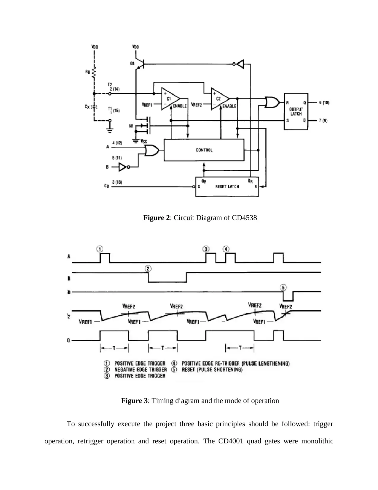
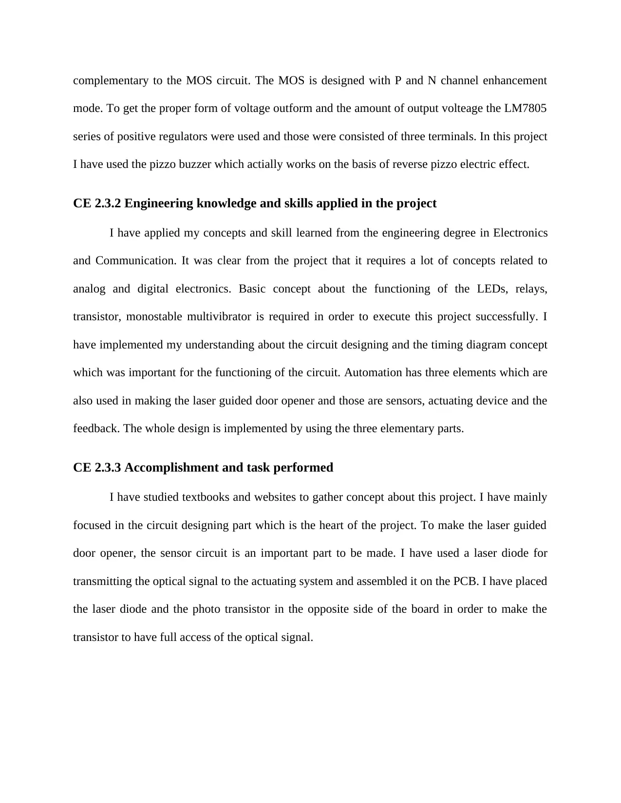
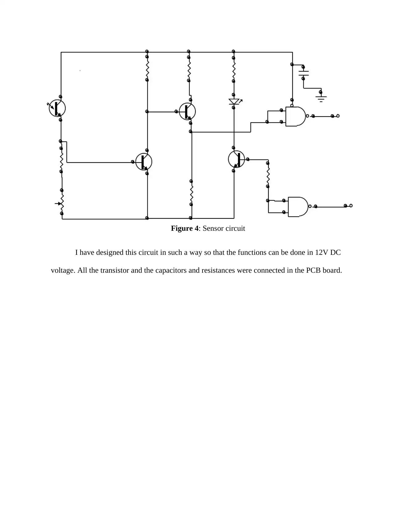
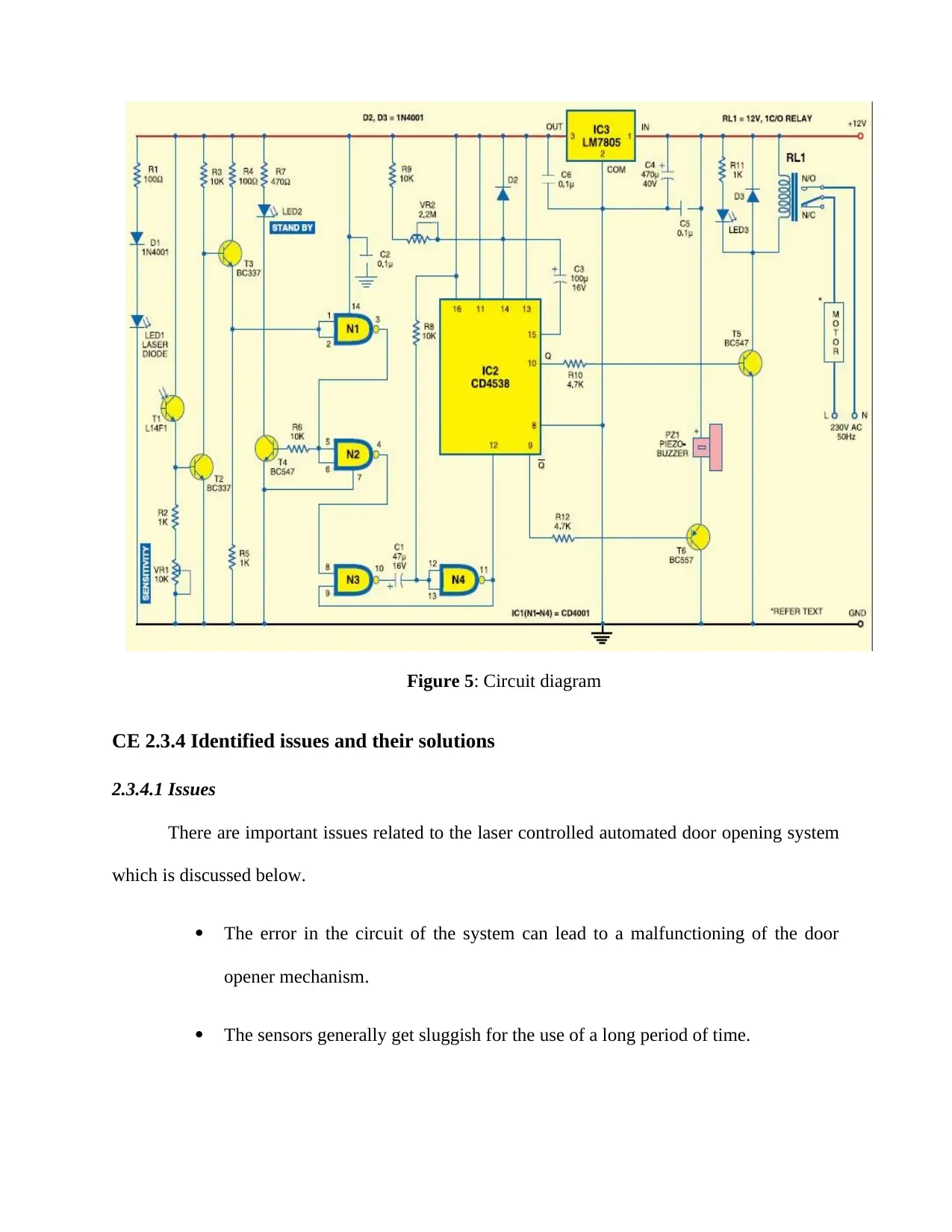
This report presents a comprehensive overview of a laser-guided door opener project undertaken by a student. The project involved designing and implementing a system that uses a laser beam to automatically open and close a door. The report details the project's objectives, which included creating an automated door opener, implementing sensor and circuit design concepts, and understanding the functionality of various electronic components such as LEDs, relays, transistors, and monostable multivibrators. The student's role encompassed circuit design, information gathering from textbooks and websites, and implementation of electromechanical control using relays. The report describes the distinctive activities, including understanding the project's theory, applying engineering knowledge, and addressing identified issues with solutions. The project utilized sensors, actuating devices, and feedback mechanisms. The report also covers collaborative work, the project review, and the student's contributions, providing insights into the project's success and future applications, such as enhancing security and convenience in various settings. The project implemented concepts from analog and digital electronics, automation principles and circuit design.

COMPETENCY
DEMONSTRATION REPORT
Career Episode 2
PRATHYUSHA REDDY KATKOORI
DEMONSTRATION REPORT
Career Episode 2
PRATHYUSHA REDDY KATKOORI
Paraphrase This Document
Need a fresh take? Get an instant paraphrase of this document with our AI Paraphraser

CE 2.1 Project Information
Name of the project: LASER GUIDED DOOR OPENER
Location of the project: Secunderabad, India
Project Duration: [Please fill]
Organization: Swami Vivekananda institute of technology
Role and Designation during the time: Electronics and Communication Engineer
CE 2.2 Project Background
CE 2.2.1 Characteristics of the project
This project was designed for dealing with a circuit which uses laser beam to automate a
door, as can be understood by the name laser guided door opener. The opening, closing and the
waiting time for the door were being depended upon the guiding of laser beam. I have used an
electromagnetic relay which functions as an automatic switch for controlling opening and the
closing of the door. The mechanism of the door had been designed based on electro mechanics. I
have also used a LED1 for the light transmitter with a photo diode. Along with a laser beam and
a photo resist transistor, the circuit comprises of not gates, two monostable multivibrator IC2
(CD4538) & IC3, few LEDS and a peizo-buzzer. The Peizo-buzzer was used as an alert when
photo resist transistor stops conducting.
The laser beam was introduced to fall on a photo transistor which is cut off when the
laser beam would not fall on the transistor and thus the circuitry stop operating which lead to

open the door automatically. This is nothing but the laser guided door opener, since the main
function is due to the laser diode inherited in it.
CE 2.2.2 Objectives developed for the project
The primary objective of this system is to create a model which is based on laser guided
door opener. The objectives of the project are discussed below.
To make an automated door opener which is laser guided.
To implement the concepts of sensors, circuit designing, analog electronics.
To understand the basic functioning of LED, relays, transistor, sensors,
monostable multivibrator and pizzo buzzer.
CE 2.2.3 My area of work
I have given this projecgt during my engineering degree in the electronics and
telecommunication engineering. I have created and planned the circuit of the system also the
basic principle of working of the sensors and the circuit. I have implemented the concept of
electromechanically controlled relay to open and close the door and also have used the LEDs for
the light transmitter with a photo diode, not gates, two monostable multivibrator IC2 (CD4538)
& IC3, few LEDs and a peizo-buzzer. I have implemented my concepts related to the analog
electronics, digital electronics, and instrumentation. I have also taken part in the circuit design of
the project and have used relevant textbooks and websites for collecting the information related
to the project.
⊘ This is a preview!⊘
Do you want full access?
Subscribe today to unlock all pages.

Trusted by 1+ million students worldwide

CE 2.2.4 Project Group
I have completed this project under the supervision of my project guide Mrs. M.
Mrudula. The names of my team members are given in the following diagram with my guide’s
name. I am also very thankful to our HOD Mr. D.S. Rao for his help in making this project.
Figure 1: Project Group
CE 2.2.5 My responsibilities throughout the project
I was responsible for making the laser guided automated door opening system by utilising
the concepts learned in my course of Electronics and Communication Engineering. It was also
my responsibility to execute the project in the required way. The conditions and the technical
features of the project were implemented in an appropriate way and it was also my responsibility
to check all the operations and the functioning related to the project. I have collected all the
information from the internet and several articles, journals and books. I was responsible for
making sure that all the data which are used during the project are true and are relevant to the
project.
Mrs. M. Mrudula
(Guide)
MANASA NARVA
(Team Member)
MOHINI PADMA
POTLA
(Team Member)
PRATHYUSHA
REDDY KATKOORI
(me)
(Te
Paraphrase This Document
Need a fresh take? Get an instant paraphrase of this document with our AI Paraphraser

CE 2.3 Distinctive Activity
CE 2.3.1 Comprehending the theory of the project
This project was created for making a laser guided door opening system. I have used an
electromechanically controlled relay mechanism which acts based on the potential and state of
the circuitry and it controls the solenoid of the door opening system for opening and closing it. I
have also implemented the LEDs for the light transmitter with a photo diode, not gates, two
monostable multivibrator IC2 (CD4538) & IC3, few LEDs and a peizo-buzzer. The laser beam
was introduced to fall on the photo transistor because the transistor conducts as long as the laser
beam falls on it. The basic principle of a photo transistor is that it gets cut off when no laser is
fallen on it and then the circuitry operates which lead to open the door automatically. This is
simply the laser guided door opener since the main function is due to the laser diode inherited in
it. Here the term LED was used to refer to the Light Emitting Diode. It mainly operates the relay
mechanism which switches the transistor and thus acts like a sensor. In this project, the
CD4538BC monostable multivibrator was used to trigger and control the switching signal and to
manipulate the regarding timing diagram.

Figure 2: Circuit Diagram of CD4538
Figure 3: Timing diagram and the mode of operation
To successfully execute the project three basic principles should be followed: trigger
operation, retrigger operation and reset operation. The CD4001 quad gates were monolithic
Figure 3: Timing diagram and the mode of operation
To successfully execute the project three basic principles should be followed: trigger
operation, retrigger operation and reset operation. The CD4001 quad gates were monolithic
⊘ This is a preview!⊘
Do you want full access?
Subscribe today to unlock all pages.

Trusted by 1+ million students worldwide

complementary to the MOS circuit. The MOS is designed with P and N channel enhancement
mode. To get the proper form of voltage outform and the amount of output volteage the LM7805
series of positive regulators were used and those were consisted of three terminals. In this project
I have used the pizzo buzzer which actially works on the basis of reverse pizzo electric effect.
CE 2.3.2 Engineering knowledge and skills applied in the project
I have applied my concepts and skill learned from the engineering degree in Electronics
and Communication. It was clear from the project that it requires a lot of concepts related to
analog and digital electronics. Basic concept about the functioning of the LEDs, relays,
transistor, monostable multivibrator is required in order to execute this project successfully. I
have implemented my understanding about the circuit designing and the timing diagram concept
which was important for the functioning of the circuit. Automation has three elements which are
also used in making the laser guided door opener and those are sensors, actuating device and the
feedback. The whole design is implemented by using the three elementary parts.
CE 2.3.3 Accomplishment and task performed
I have studied textbooks and websites to gather concept about this project. I have mainly
focused in the circuit designing part which is the heart of the project. To make the laser guided
door opener, the sensor circuit is an important part to be made. I have used a laser diode for
transmitting the optical signal to the actuating system and assembled it on the PCB. I have placed
the laser diode and the photo transistor in the opposite side of the board in order to make the
transistor to have full access of the optical signal.
Paraphrase This Document
Need a fresh take? Get an instant paraphrase of this document with our AI Paraphraser

Figure 4: Sensor circuit
I have designed this circuit in such a way so that the functions can be done in 12V DC
voltage. All the transistor and the capacitors and resistances were connected in the PCB board.
I have designed this circuit in such a way so that the functions can be done in 12V DC
voltage. All the transistor and the capacitors and resistances were connected in the PCB board.

Figure 5: Circuit diagram
CE 2.3.4 Identified issues and their solutions
2.3.4.1 Issues
There are important issues related to the laser controlled automated door opening system
which is discussed below.
The error in the circuit of the system can lead to a malfunctioning of the door
opener mechanism.
The sensors generally get sluggish for the use of a long period of time.
⊘ This is a preview!⊘
Do you want full access?
Subscribe today to unlock all pages.

Trusted by 1+ million students worldwide

2.3.4.2 Solutions
To overcome the above-mentioned issues related to the system, the following solutions
are to be taken:
The circuit diagram should be designed in a planned way.
The system should be maintained on a regular basis to achieve better response
with long durability.
CE 2.3.5 Plan to produce creative and innovative work
This project was designed in such a planned way so that it could be used in many future
applications. The most important scope of this project is that it can increase the user’s security
and convenience. In several sectors like home, offices, schools this system can be used for
providing automated door closing system. The most important fact related to the future scope is
that this system can help the physically challenged persons a lot to get access through doors. This
project can also be used in understanding the functioning and the principles of several elements
from the circuit diagram of the project. The risk factors and the possible malfunctioning of the
system can also e identified previously by implementing this project.
CE 2.3.6 Collaborative work
I have collobrated on this project with my classmates Mohini Padma Potla and Manasa
Narva who have assisted me during this project and I must say that they were really enthusiastic
and focused during the project completion. I have also conveyed my gratitude and thanking to
my project guide Mrs. M. Mrudula and our HOD Mr. D.S. Rao and we cannot make the project
without their support and care. During making of the documentation of this project my team
Paraphrase This Document
Need a fresh take? Get an instant paraphrase of this document with our AI Paraphraser

mates have helped me a lot in collecting information. They have also assisted me in making the
circuit diagram for this project.
CE 2.4 Project Review
CE 2.4.1 Project Overview
After completion of the project, it can be concluded that laser-guided door opener
improves the convenience and security of the user. In this project, all concepts relating to the
sensors, relay, and control circuit and alarm system are discussed. I have also understood the
concepts related to the phototransistor and the pizzo electric effect which are primary concepts to
be used in this project. I have also used my knowledge in designing the circuit by connecting all
the elements according to the pin diagram according to the image shown in figure 5. From the
circuit diagram it can be said that the actuating element is the relay which is controlled by the
phototransistors. The IC2CD4538 also sends the controlling signal to the transistors and the
LEDs are acting as the source of the optical signal which are fed to the transistor.
CE 2.4.2 My contribution to work
It was a good example of a project in which I have applied my skills and knowledge from
my engineering capability. I have used all the circuit elements and the sensors and the photo
transistors for proper implementation of the project. For proper execution of the project I have
planned all the design in order to make it well executed. I have completed this project with best
of my capability by contributing in the circuit design, planning and in several operations. I have
also designed the circuit according to the pin diagram given in the figure 5. I have carried out the
functions several times to evaluate the errors in the system and also informed those to my

teammates and my project guide. After testing all the elements and functions I have created the
documentation of the project and submitted to the university.
⊘ This is a preview!⊘
Do you want full access?
Subscribe today to unlock all pages.

Trusted by 1+ million students worldwide
1 out of 12

Your All-in-One AI-Powered Toolkit for Academic Success.
+13062052269
info@desklib.com
Available 24*7 on WhatsApp / Email
Unlock your academic potential
Copyright © 2020–2025 A2Z Services. All Rights Reserved. Developed and managed by ZUCOL.