Instrumentation Project: Dark Detector Sensor with LDR Components

Verified

Added on  2023/01/05

|27
|4299
|20
Project
AI Summary
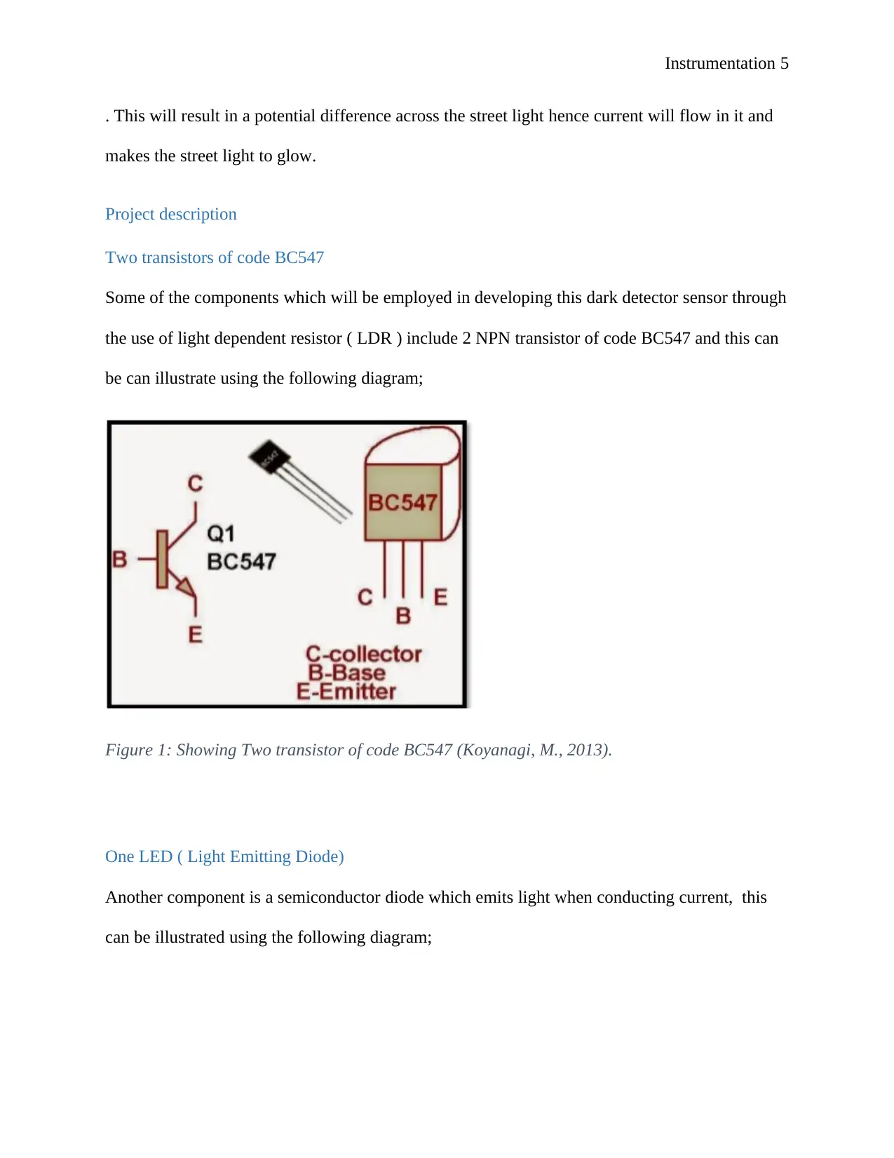
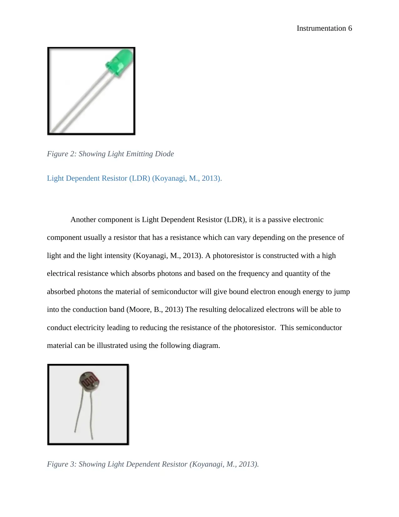
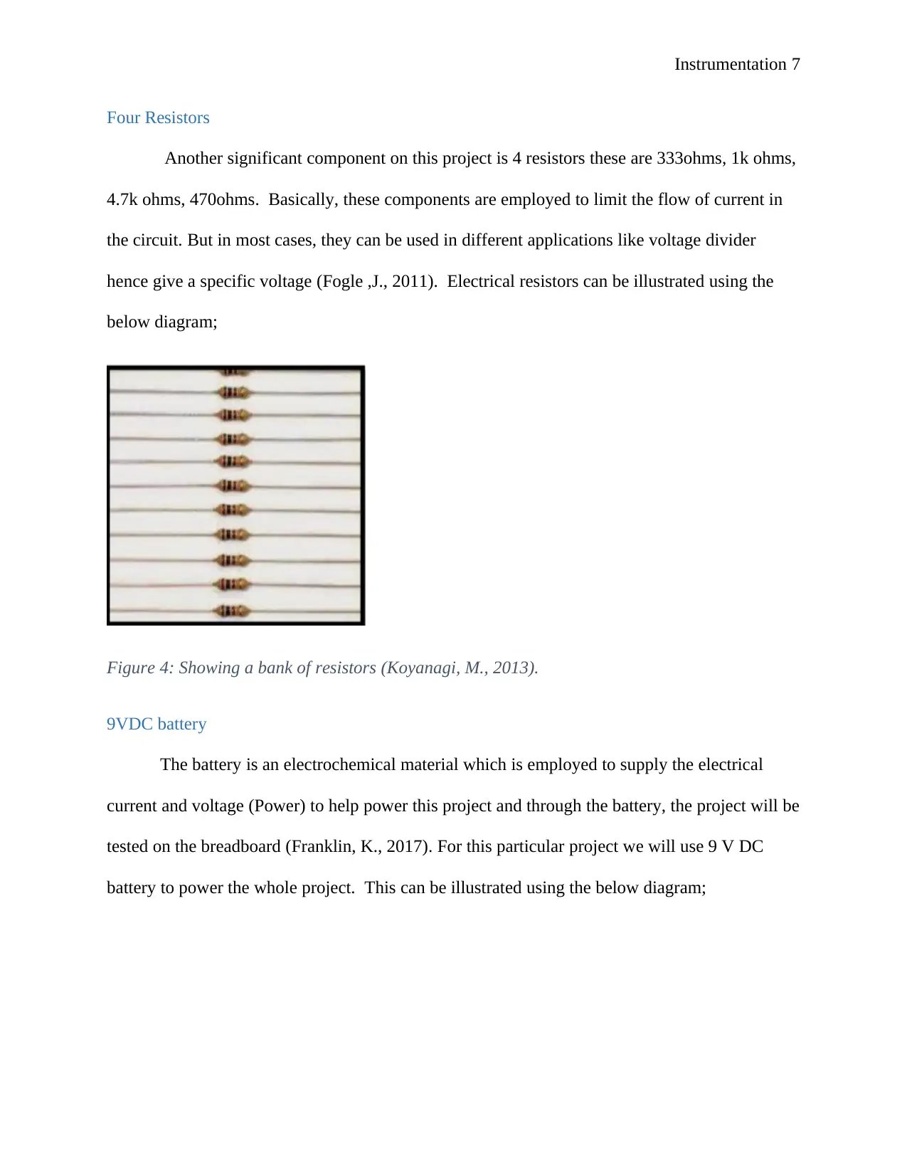
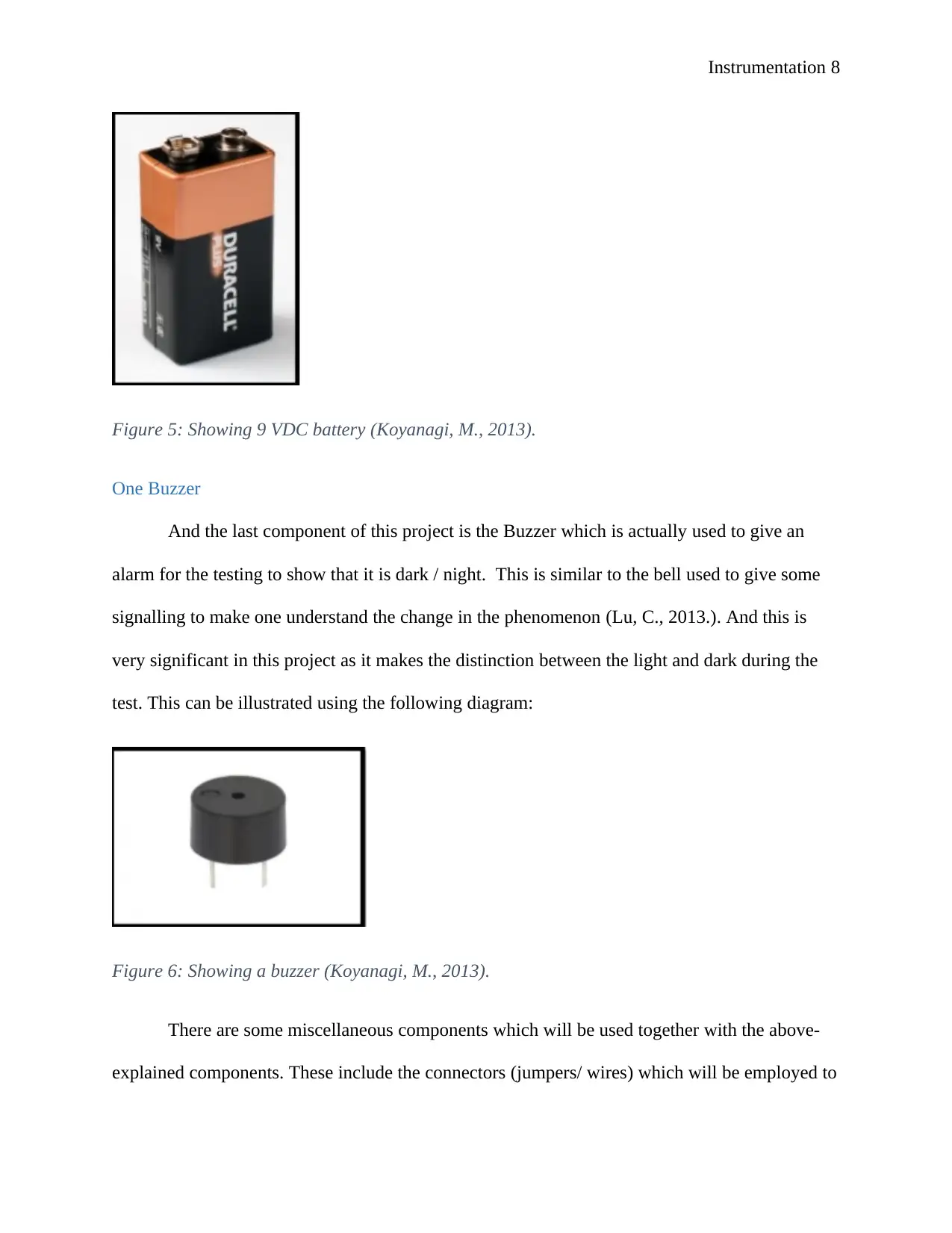
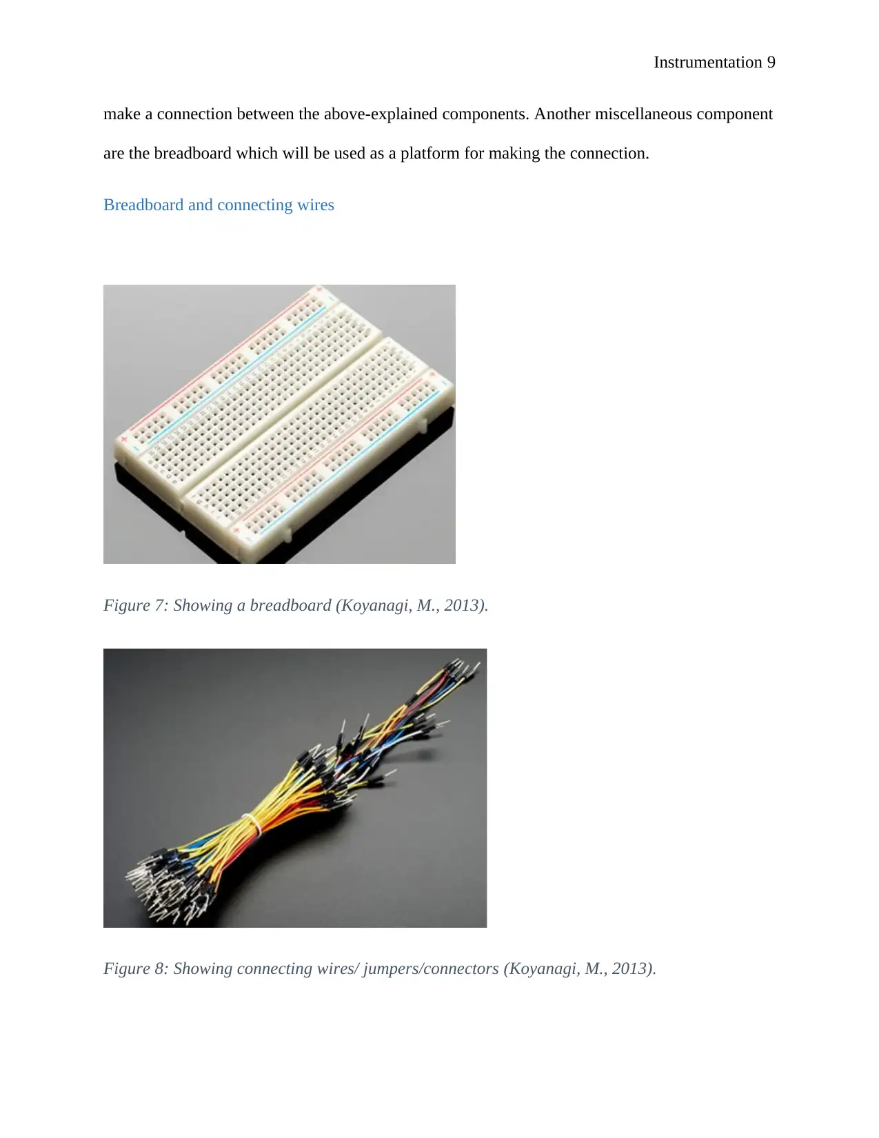
This project report details the design and implementation of a dark detector sensor using a Light Dependent Resistor (LDR). The project utilizes components such as BC547 transistors, an LED, a buzzer, resistors, and a 9VDC battery, all connected on a breadboard. The report includes detailed explanations of each component's function, circuit diagrams, schematic diagrams, and the step-by-step procedure for connecting the components. The core concept revolves around the LDR's ability to change its resistance based on light intensity, enabling the circuit to detect darkness. When light is absent, the LDR's resistance increases, triggering the transistors to activate the LED and buzzer. The report also discusses the input measurand (light intensity), sensor input, and the structure and working principle of the LDR, along with its advantages and disadvantages. The project aims to demonstrate the practical application of LDRs in dark detection and automatic switching applications, such as street lights. Furthermore, the report touches upon data acquisition (DAQ) card properties and includes relevant figures and diagrams to illustrate the circuit and its functionality.
tabler-icon-diamond-filled.svg

Contribute Materials

Your contribution can guide someone’s learning journey. Share your documents today.
Document Page
Instrumentation 1
INSTRUMENTATION
By Name
Course
Instructor
Institution
Location
Date
tabler-icon-diamond-filled.svg

Secure Best Marks with AI Grader

Need help grading? Try our AI Grader for instant feedback on your assignments.
Document Page
Instrumentation 2
Contents
Introduction.................................................................................................................................................2
Project description.......................................................................................................................................3
Two transistor of code BC547.................................................................................................................3
One LED ( Light Emitting Diode)...........................................................................................................4
Light Dependent Resistor (LDR) (Terakita, A., 2013)............................................................................4
Four Resistors..........................................................................................................................................5
9VDC battery..........................................................................................................................................6
One Buzzer..............................................................................................................................................6
Breadboard and connecting wires............................................................................................................7
The procedure of connection of components in project...........................................................................8
Input measurand....................................................................................................................................14
Sensor Input...........................................................................................................................................15
Structure and working principle.........................................................................................................15
Advantages of Light Dependent Resistor..........................................................................................17
Disadvantages of Light-Dependent sensors...........................................................................................17
DAQ Card Properties.............................................................................................................................18
Table of figures
Figure 1: Showing Two transistor of code BC547.......................................................................................5
Figure 2: Showing Light Emitting Diode....................................................................................................5
Figure 3: Showing Light Dependent Resistor..............................................................................................6
Figure 4: Showing a bank of resistors..........................................................................................................6
Figure 5: Showing 9 VDC battery...............................................................................................................7
Figure 6: Showing a buzzer.........................................................................................................................8
Figure 7: Showing a breadboard..................................................................................................................8
Figure 8: Showing connecting wires/ jumpers/connectors...........................................................................9
Figure 9: Showing a transistor connected on the breadboard.......................................................................9
Figure 10: Showing 2 transistor connected on breadboard........................................................................10
Figure 11: Showing several components connected on the breadboard.....................................................11
Figure 12 Showing several components of LDR connected on the breadboard.........................................11
Figure 13: Showing several components of LDR connected on the breadboard........................................12
Figure 14: Showing all LDR project circuit connected..............................................................................13
Figure 15: Showing circuit diagram of the project....................................................................................14
Figure 16: Showing schematic diagram of this project..............................................................................15
Figure 17: Showing structure of LDR.......................................................................................................16
Document Page
Instrumentation 3
Figure 18: Showing a graph illustrating the relationship between electrical resistance and light intensity
.................................................................................................................................................................. 18
Figure 19: Showing block diagram below illustrates the data acquisition card..........................................20
Figure 20: Showing DAQ simulation........................................................................................................21
Figure 21: Showing a flow chart diagram of DAQ....................................................................................22
Figure 22: Showing input circuit of Light-Dependent sensor....................................................................23
Figure 23: Showing the actuator of the light-dependent sensor.................................................................24
Document Page
Instrumentation 4
Introduction
Just as its name suggests, this type of sensor (Light Dependent Sensor) is made from
some materials which have the ability to change their electrical resistance depending on the
presence and degree of light falling on them. Some of the materials which possess such
characteristic include cadmium Sulphide, Basically, this type of sensor will enable current to
flow when there is darkness (reduce the electrical resistance) and will hinder the flow of
electrical current during the day / when there is light (electrical resistance will increase).
It hence means that this type of sensor exclusively depends on the presence/absence of
light to undertake a particular operation as specified by the designer. For this project, the light
dependent resistor sensor will be employed to monitor the presence of light which will aid in
dark detection. Dark sensor using a Light Dependent Resistor can be used to monitor and check
the presence of light in a given area and takes action automatically without being operated
manually. This concept has been used in controlling the switching ON of street light at night and
switching them OFF during the day when there is natural light.
A brief operation of this system is that when there is less light the resistance of LDR will highly
increase and due to ohms law given below;
V=IR . . . . . . . . . . . . . . . . . . . . . . . . . . . . . . . . . . . . . . . . . . . . . . . . . . . . . . . . . . . . . . . . . . . . . . 1
And from ohms law in equation 1 above, the current in the base will significantly reduce and
this leads to very low electrical current in the base, therefore the PNP transistor will switch ON.
This will make the transistor amplify the current that moves from the collector to emitter
(Suryanarayana, S., 2014).
tabler-icon-diamond-filled.svg

Secure Best Marks with AI Grader

Need help grading? Try our AI Grader for instant feedback on your assignments.
Document Page
Instrumentation 5
. This will result in a potential difference across the street light hence current will flow in it and
makes the street light to glow.
Project description
Two transistors of code BC547
Some of the components which will be employed in developing this dark detector sensor through
the use of light dependent resistor ( LDR ) include 2 NPN transistor of code BC547 and this can
be can illustrate using the following diagram;
Figure 1: Showing Two transistor of code BC547 (Koyanagi, M., 2013).
One LED ( Light Emitting Diode)
Another component is a semiconductor diode which emits light when conducting current, this
can be illustrated using the following diagram;
Document Page
Instrumentation 6
Figure 2: Showing Light Emitting Diode
Light Dependent Resistor (LDR) (Koyanagi, M., 2013).
Another component is Light Dependent Resistor (LDR), it is a passive electronic
component usually a resistor that has a resistance which can vary depending on the presence of
light and the light intensity (Koyanagi, M., 2013). A photoresistor is constructed with a high
electrical resistance which absorbs photons and based on the frequency and quantity of the
absorbed photons the material of semiconductor will give bound electron enough energy to jump
into the conduction band (Moore, B., 2013) The resulting delocalized electrons will be able to
conduct electricity leading to reducing the resistance of the photoresistor. This semiconductor
material can be illustrated using the following diagram.
Figure 3: Showing Light Dependent Resistor (Koyanagi, M., 2013).
Document Page
Instrumentation 7
Four Resistors
Another significant component on this project is 4 resistors these are 333ohms, 1k ohms,
4.7k ohms, 470ohms. Basically, these components are employed to limit the flow of current in
the circuit. But in most cases, they can be used in different applications like voltage divider
hence give a specific voltage (Fogle ,J., 2011). Electrical resistors can be illustrated using the
below diagram;
Figure 4: Showing a bank of resistors (Koyanagi, M., 2013).
9VDC battery
The battery is an electrochemical material which is employed to supply the electrical
current and voltage (Power) to help power this project and through the battery, the project will be
tested on the breadboard (Franklin, K., 2017). For this particular project we will use 9 V DC
battery to power the whole project. This can be illustrated using the below diagram;
tabler-icon-diamond-filled.svg

Paraphrase This Document

Need a fresh take? Get an instant paraphrase of this document with our AI Paraphraser
Document Page
Instrumentation 8
Figure 5: Showing 9 VDC battery (Koyanagi, M., 2013).
One Buzzer
And the last component of this project is the Buzzer which is actually used to give an
alarm for the testing to show that it is dark / night. This is similar to the bell used to give some
signalling to make one understand the change in the phenomenon (Lu, C., 2013.). And this is
very significant in this project as it makes the distinction between the light and dark during the
test. This can be illustrated using the following diagram:
Figure 6: Showing a buzzer (Koyanagi, M., 2013).
There are some miscellaneous components which will be used together with the above-
explained components. These include the connectors (jumpers/ wires) which will be employed to
Document Page
Instrumentation 9
make a connection between the above-explained components. Another miscellaneous component
are the breadboard which will be used as a platform for making the connection.
Breadboard and connecting wires
Figure 7: Showing a breadboard (Koyanagi, M., 2013).
Figure 8: Showing connecting wires/ jumpers/connectors (Koyanagi, M., 2013).
Document Page
Instrumentation 10
The procedure of connection of components in the project
The first step is to connect the first transistor in a well operating breadboard, after that the
second transistor is connected straightaway. The connection of the transistor on the breadboard is
illustrated as below;
Figure 9: Showing a transistor connected to the breadboard (Koyanagi, M., 2013).
The next step is to connect the connecting wires across the emitter pin in both the first
and second transistor. This is connected in a way that negative terminal of the battery (bottom, a
lowest row of the breadboard), this is illustrated in the diagram as below;
Figure 10: Showing 2 transistor connected on a breadboard(Terakita, A., 2013).
tabler-icon-diamond-filled.svg

Secure Best Marks with AI Grader

Need help grading? Try our AI Grader for instant feedback on your assignments.
Document Page
Instrumentation 11
The next step is to connect a connector (wire) across the base pin of transistor Q” and the
collector pin Q1. After that, a resistor of 1k is then put across a positive terminal of the battery.
This is done on the topmost row of the breadboard. The connection of components on the
breadboard up to this point can be illustrated as below;
Figure 11: Showing several components connected to the breadboard (Koyanagi, M., 2013).
In the next step, Light dependent resistor is inserted across the positive terminal of the battery
(top side on the breadboard and the base terminal of the Q1. The connection is illustrated as
below;
Document Page
Instrumentation 12
Figure 12 Showing several components of LDR connected on the breadboard (Koyanagi, M.,
2013).
A resistor of 330 ohms is placed across the base pin of transistor of Q1 and the negative terminal
of the battery( lower part of the breadboard). And the diagram below illustrates the connection;
Figure 13: Showing several components of LDR connected on the breadboard (Koyanagi, M.,
2013).
Document Page
Instrumentation 13
The l st step is to connect 330 ohms across the positive terminal of the 9VDC battery ( at
the topmost part of the breadboard) and the anode terminal of the light emitting diode then
connect the cathode terminal of the light emitting diode to the collector pin of the Q2
( transistor). The same will be done to the sound buzzer and this will make the complete
connection of the project (Kumaar, A., 2010).This connection on the breadboard is illustrated
using the below diagram;
Figure 14: Showing all LDR project circuit connected (Koyanagi, M., 2013).
At this point, the circuit is very ready for testing and the output can be checked. The
expected outcome of this project is that when there is no light (when the Light dependent resistor
is physically blocked) The LED will glow indicating that the street lights are turned ON, at the
same time the buzzer will give an alarm by producing sound on that effect (Da Silva, D., 2016)
After the circuit connecting the below is the circuit diagram of the project;
tabler-icon-diamond-filled.svg

Paraphrase This Document

Need a fresh take? Get an instant paraphrase of this document with our AI Paraphraser
Document Page
Instrumentation 14
Figure 15: Showing circuit diagram of the project (Da Silva D., 2016)
While the schematic diagram of this project is illustrated as in the diagram below;
Document Page
Instrumentation 15
Figure 16: Showing schematic diagram of this project (Da Silva, D., 2016)
Input measurand
The input of this sensor (input measurand ) is the light intensity, as discussed above
when there is darkness the resistance of the LDR will reduce while when there is light the
resistance will increase. Therefore this type of sensor is very Unique to be used as a dark detector
(Sohag, M., 2015). This concept best suits to be used in switching ON and OFF of the street
lights. For this type of sensor, there is no defined light intensity range where it will work
however when the light intensity increases the resistance of the LDR increase (thus this is
continuous parameter but not discrete) (Tan, Z., 2013). And as the light intensity increases the
resistance decreases hence the current will flow and the LED will light. The brightness of the
LED increases with the increase of darkness (decrease in natural light).
Document Page
Instrumentation 16
Sensor Input
Just as given above, the measurand of this type of sensor is light, the sensor will
exclusively measure the light intensity and then take appropriate actions. The working principle
of this sensor is given below;
Structure and working principle
The diagram below best help in the understanding of the working principle of the Light
Dependent sensor.
Figure 17: Showing structure of LDR (Da Silva, D., 2016)
The coil-like track in the above diagram is Cadmium Sulphide film that also passes
through the side The bottom and the top of the sensor are a film of metal that is connected to the
terminal leads (Tseng, K.J., 2011). This is designed in a way to give the maximum possible
contact area with the 2 films of metal. In the absence of light, it is designed to have the sensor is
designed to have higher electrical resistance which is in the range of mega ohms. Immediately
the light falls on the surface of the sensor, the electrons are liberated and the conductivity of the
tabler-icon-diamond-filled.svg

Secure Best Marks with AI Grader

Need help grading? Try our AI Grader for instant feedback on your assignments.
Document Page
Instrumentation 17
material will be higher. But when light intensity is more than a given frequency, there will be the
absorption of the photons by the semiconductor and this will give energy to electrons the band.
This energy should be enough to enable it to jump into the conduction band. When this happens
it will make the delocalized electrons and holes (sometimes) to conduct electricity hence
reducing the electrical resistance (this is done dramatically to a less 1 kohms ). The following
equation explains the relationship between
R= A Ea . . . . . . . . . . . . . . . . . . . . . . . . . . . . . . . . . . . . . . . . . . . . . . . . . . . . . . . . . . . . . . . . . . . . . . .
. . . . . . . . 2
Where A and a are constants, R is resistance and E is illumination (lux)
Tis equation can be reduced to equation 3 to perfectly give the relationship between the two
variables;
R=kE . . . . . . . . . . . . . . . . . . . . . . . . . . . . . . . . . . . . . . . . . . . . . . . . . . . . . . . . . . . . . . . . . . . . . . . . .
. . . . . . . . . 3
Where k is constant
The value of constant a fully depend on the type of CdS used as well as the manufacturing
process. This value always ranges from 0.7 to 0.9.
Graphically, this relationship can be given as below;
Document Page
Instrumentation 18
Figure 18: Showing a graph illustrating the relationship between electrical resistance and light
intensity (Da Silva, D., 2016)
Advantages of Light Dependent Resistor
Basically, light-dependent is relatively cheap and are also easy to access in different
forms, shapes and sizes. Practical Light Dependent resistors are available in different package
style and sizes and the popular size is having a face of the dimension of about 10mm. This
sensor also use very little voltage and current hence little power consumption during their
operation.
Disadvantages of Light-Dependent sensors
Document Page
Instrumentation 19
Light-dependent sensors are highly inaccurate with the time response of about tense and
sometimes hundreds of milliseconds.
The input to this sensor is in continuous form just as mentioned above, the electrical
resistance increases with the reduction in light intensity, this occurs gradually hence it is
continuous. The input signal is continuous it makes the input signal to be analogue (Shnayder,
V., 2015). The LDR faces a limitation as it needs small milliseconds or more to fully respond to
the variations in the intensity of light. This limitation of the LDR does not highly affect the
operation of this light dependent resistor.
DAQ Card Properties
For instrumentation (LDR sensors) is employed in measuring the current and voltage
which is fed into the system. There are other parameters of the sensor which the data acquisition
will measure, this includes temperature and pressure. The block diagram below illustrates the
data acquisition card;
tabler-icon-diamond-filled.svg

Paraphrase This Document

Need a fresh take? Get an instant paraphrase of this document with our AI Paraphraser
Document Page
Instrumentation 20
Figure 19: Showing block diagram below illustrates the data acquisition card (Shnayder, V.,
2015).
The input voltage to this system is 9 VDC while the current is 10mA this enables the
system to operate effectively in detecting the presence of light and take actions effectively. When
the specified voltage and current for this sensor are fed into a DAQ the following waveforms are
produced.
Document Page
Instrumentation 21
Figure 20: Showing DAQ simulation (Shnayder, V., 2015).
Software
Data acquisition software are so many including MATLAB, DAP studio, and Lab View
among others. For this particular project MATLAB was employed as a DAQ software. For the
DAQ to produce the required results, correct scaling of the axes to make the waves be read. This
software will actually help in giving the power used by the sensor in its operation (Woulfe, F.J.,
2018). This power is rather given in the form of voltage and current which will help to obtain the
actual power through multiplication since power = Voltage * current. In a flow diagram, this can
be illustrated using the following flow diagram.
Document Page
Instrumentation 22
Figure 21: Showing a flow chart diagram of DAQ (Sullivan, F.J., 2018).
Control/Actuator element
From the basic definition, this is a device which is responsible for the moving hence
controlling action or mechanism. In this system, the definition is not quite clear. But still, it
gives the sense of what happens. The actuator here will help in controlling the switching ON /
OFF the street light as stated above. The actuator is this project is the holes and electrons which
when the light falls on them (material of the CdS. This actuator will enable the material to
conduct electricity by reducing the electrical resistance when the light intensity reduces
(Daimiwal, N., 2014). But when the light intensity increases the electrical resistance reduce.
Basically, that is how the control parameter of the actuator will operate.
tabler-icon-diamond-filled.svg

Secure Best Marks with AI Grader

Need help grading? Try our AI Grader for instant feedback on your assignments.
Document Page
Instrumentation 23
The increase/ decrease in the light intensity is gradual/continuous therefore the output of
this actuator is analogue form. The output of the DAQ is in analogue form since the output
signal is in continuous form. The working of this actuator is that when the light falls on the
sensor the material of CdS the electrical resistance reduces (more current passes hence the LED
glows showing that street lights are lighting /ON) while when the light which falls on the sensor
is less the electrical resistance will increase showing that less current will pass through the
conductor (Vrileuis, A., 2013).
SENSOR/ACTUATOR CIRCUIT
The circuit input of this sensor is illustrated using the below diagram;
Figure 22: Showing input circuit of Light-Dependent sensor (Vrileuis, A., 2013).
The input circuit obtains the signals from the sun and then the actuator will take the
appropriate actions on the light depending on its intensity. Basically, this project would not
require any filter or any amplifier but rather this can be achieved by ensuring that there is no
shadow or obstacle where the sensor is situated. But in some cases, an amplifier can be
Document Page
Instrumentation 24
employed to help amplify the current from the collector to the emitter. The sensor should be
placed in a place where it receives maximum sunlight to enable the sensor to operate effectively
as required. As soon as the sensor detects the presence of sunlight the signal will be sent
immediately to the actuator to help it take the required action. With the sensor perfectly
communicating with the actuator within a very short time, it makes it very possible for this
system to have a relatively quick response and this makes it possible to be used in controlling the
Switch ON and OFF of the street lights. This can be illustrated using the following diagram.
Figure 23: Showing actuator of the light-dependent sensor (Vrileuis, A., 2013).
Document Page
Instrumentation 25
Bibliography
Da Silva, D. and Acosta-Avalos, D., 2016. Light-dependent resistance as a sensor in
spectroscopy setups using pulsed light and compared with electret microphones. Sensors, 6(5),
pp.514-525.
Daimiwal, N., Sundhararajan, M. and Shriram, R., 2014, April. Comparative analysis of LDR
and OPT 101 detectors in reflectance-type PPG sensor. In 2014 International Conference on
Communication and Signal Processing (pp. 1078-1081). IEEE.
Fogle, J., Parson, K.G., Dahm, N.A. and Holmes, T.C., 2011. CRYPTOCHROME is a blue-light
sensor that regulates neuronal firing rate. Science, 331(6023), pp.1409-1413.
Franklin, K., Allen, T. and Whitelam, G.C., 2017. Phytochrome A is an irradiance‐dependent red
light sensor. The Plant Journal, 50(1), pp.108-117.
Huynh, T.P., Tan, Y.K. and Tseng, K.J., 2011, November. Energy-aware wireless sensor
network with ambient intelligence for smart LED lighting system control. In IECON 2011-37th
Annual Conference of the IEEE Industrial Electronics Society (pp. 2923-2928). IEEE.
Koyanagi, M., Takada, E., Nagata, T., Tsukamoto, H. and Terakita, A., 2013. Homologs of
vertebrate Opn3 potentially serve as a light sensor in nonphotoreceptive tissue. Proceedings of
the National Academy of Sciences, 110(13), pp.4998-5003.
tabler-icon-diamond-filled.svg

Paraphrase This Document

Need a fresh take? Get an instant paraphrase of this document with our AI Paraphraser
Document Page
Instrumentation 26
Kumaar, A., 2010. Intelligent lighting system using wireless sensor networks. arXiv preprint
arXiv:1101.0203.
Kumar, V.S.S. and Suryanarayana, S., 2014. Automatic dual Axis sun tracking system using
LDR sensor. International Journal of Current Engineering and Technology, 4(5), pp.3214-3217.
Moore, B., Zhou, L., Rolland, F., Hall, Q., Cheng, W.H., Liu, Y.X., Hwang, I., Jones, T. and
Sheen, J., 2013. Role of the Arabidopsis glucose sensor HXK1 in nutrient, light, and hormonal
signaling. Science, 300(5617), pp.332-336.
Shnayder, V., Chen, B.R., Lorincz, K., Fulford-Jones, T.R. and Welsh, M., 2015. Sensor
networks in LDR street lighting.
Sohag, H.A., Hasan, M., Khatun, M. and Ahmad, M., 2015, December. An accurate and efficient
solar tracking system using image processing and LDR sensor. In 2015 2nd International
Conference on Electrical Information and Communication Technologies (EICT) (pp. 522-527).
IEEE.
Tan, Y.K., Huynh, T.P. and Wang, Z., 2013. Smart personal sensor network control for energy
saving in DC grid powered LED lighting system. IEEE Transactions on smart grid, 4(2), pp.669-
676.
Document Page
Instrumentation 27
Vrileuis, A., 2013. Pemantau Lalu Lintas dengan Sensor LDR Berbasis Mikrokontroler
ATmega16. Jurnal rekayasa elektrika, 10(3), pp.142-146.
Wang, J.M. and Lu, C., 2013. Design and implementation of a sun tracker with a dual-axis single
motor for an optical sensor-based photovoltaic system. Sensors, 13(3), pp.3157-3168.
Woulfe, P., O'Keeffe, S. and Sullivan, F.J., 2018, February. Optical fibre luminescence sensor
for real-time LDR brachytherapy dosimetry. In Optical Fibers and Sensors for Medical
Diagnostics and Treatment Applications XVIII (Vol. 10488, p. 1048813). International Society
for Optics and Photonics.
chevron_up_icon
1 out of 27
circle_padding
hide_on_mobile
zoom_out_icon
logo.png

Your All-in-One AI-Powered Toolkit for Academic Success.

Available 24*7 on WhatsApp / Email

[object Object]