Queensland University of Technology: Leap Motion and Exoskeleton
VerifiedAdded on 2021/06/17
|6
|5525
|178
Project
AI Summary
This project analyzes the working of a Leap Motion sensor-controlled exoskeleton, focusing on design for gait, posture, and gesture assistance, particularly for elderly individuals. The research incorporates power, computer hardware, and software to ensure proper device development, referencing predictions of technological advancements in leap motion controllers. The project details the Leap Motion sensor, its functionality, and its integration with an exoskeleton mechanical frame, referencing various methods and data sources. It covers the methodology, including the Leap Motion sensor's description, working principles, and control panel settings. The project discusses the Leap Motion sensor's operation, comprising two cameras and three LEDs, and how it translates raw sensor data into usable information for engineering applications. It also describes the exoskeleton frame's design, material selection (aluminum), and construction, along with its specifications and objectives for supporting the body, occupying low volume, and adapting to different body shapes. The report provides specifications for building the mechanical frame for the exoskeleton and includes figures and diagrams. The project aims to create a wearable machine powered by electric motors, hydraulic systems, or pneumatics, combining advanced technologies for limb mobility and endurance.
Research Methods for Engineers
LEAP MOTION SENSORS AND THE
EXOSKELETON FRAME
Lakhan Nar, Darshan Patel, Bhavin Vyas, Samir Finava
Engineering Faculty
Queensland University of technology
2, George Street, Brisbane, 4001, Qld, Australia
Abstract— main aim in research reported here is to analyze the
working of a Leap motion sensor controlled exoskeleton. This
research explores various ways of designing the advanced devices
in such a way that it serves to help gait posture and gesture
designed to fit elderly people. Power and computer hardware and
software are incorporated in order to ensure that the device is
developed in a proper way. Recent studies predict that by 2060,
developer companies dealing with leap motion controllers that
offer complex technological solutions and sustain the society. For
several years the leap motion has been operating smoothly on
bringing hand gestures to virtual reality. It is therefore important
when an individual use hand to move digital objects from one
position to the other in a more natural way than using a certain
controller.
I. INTRODUCTION OF THE RESEARCH
Project describes working in the leap motion sensors,
working of the exoskeleton frame. the use of leap motion
sensors to control the exoskeleton frame and the
working of the exoskeleton frame to control the leap motion
sensors. Different information from different sources have
facilitated the research work.
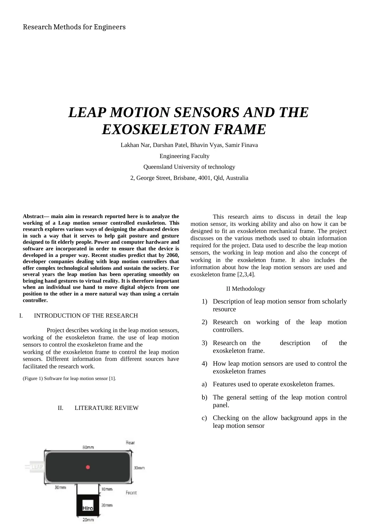
(Figure 1) Software for leap motion sensor [1].
II. LITERATURE REVIEW
This research aims to discuss in detail the leap
motion sensor, its working ability and also on how it can be
designed to fit an exoskeleton mechanical frame. The project
discusses on the various methods used to obtain information
required for the project. Data used to describe the leap motion
sensors, the working in leap motion and also the concept of
working in the exoskeleton frame. It also includes the
information about how the leap motion sensors are used and
exoskeleton frame [2,3,4].
II Methodology
1) Description of leap motion sensor from scholarly
resource
2) Research on working of the leap motion
controllers.
3) Research on the description of the
exoskeleton frame.
4) How leap motion sensors are used to control the
exoskeleton frames
a) Features used to operate exoskeleton frames.
b) The general setting of the leap motion control
panel.
c) Checking on the allow background apps in the
leap motion sensor
LEAP MOTION SENSORS AND THE
EXOSKELETON FRAME
Lakhan Nar, Darshan Patel, Bhavin Vyas, Samir Finava
Engineering Faculty
Queensland University of technology
2, George Street, Brisbane, 4001, Qld, Australia
Abstract— main aim in research reported here is to analyze the
working of a Leap motion sensor controlled exoskeleton. This
research explores various ways of designing the advanced devices
in such a way that it serves to help gait posture and gesture
designed to fit elderly people. Power and computer hardware and
software are incorporated in order to ensure that the device is
developed in a proper way. Recent studies predict that by 2060,
developer companies dealing with leap motion controllers that
offer complex technological solutions and sustain the society. For
several years the leap motion has been operating smoothly on
bringing hand gestures to virtual reality. It is therefore important
when an individual use hand to move digital objects from one
position to the other in a more natural way than using a certain
controller.
I. INTRODUCTION OF THE RESEARCH
Project describes working in the leap motion sensors,
working of the exoskeleton frame. the use of leap motion
sensors to control the exoskeleton frame and the
working of the exoskeleton frame to control the leap motion
sensors. Different information from different sources have
facilitated the research work.
(Figure 1) Software for leap motion sensor [1].
II. LITERATURE REVIEW
This research aims to discuss in detail the leap
motion sensor, its working ability and also on how it can be
designed to fit an exoskeleton mechanical frame. The project
discusses on the various methods used to obtain information
required for the project. Data used to describe the leap motion
sensors, the working in leap motion and also the concept of
working in the exoskeleton frame. It also includes the
information about how the leap motion sensors are used and
exoskeleton frame [2,3,4].
II Methodology
1) Description of leap motion sensor from scholarly
resource
2) Research on working of the leap motion
controllers.
3) Research on the description of the
exoskeleton frame.
4) How leap motion sensors are used to control the
exoskeleton frames
a) Features used to operate exoskeleton frames.
b) The general setting of the leap motion control
panel.
c) Checking on the allow background apps in the
leap motion sensor
Paraphrase This Document
Need a fresh take? Get an instant paraphrase of this document with our AI Paraphraser
Research Methods for Engineers
d) Tracking settings used in leap motion sensors in
controlling the exoskeleton frames.
5) How exoskeleton frames are used to control the
leap motion sensors.
6)
a) Use of algorithm in frames to control the sensors
b) Graphical representation of the steps used to
control the sensors
Methods
It describes the report by giving out related
information about the study of the work. Description on the
instruments used to illustrate the framework of the report.
How information is managed, process of collecting the data
from various concepts, illustrations of the figures and
diagrams describing the statistical data about the project.
Discussions
1. Leap Motion Sensor
This is a computerized hardware device that is
specifically designed to maintain motions as input and analogs
to a computer peripherals and mouse. It a software that is
designed for hand tracking in various virtual reality dimension.
This sensor is a controller USB peripheral system that is built
and put on a physical computer in a position that ensures it is
facing upwards. Also, the controller can be inserted on to a
virtual handset.
By utilizing monochromatic IR cameras plus 3
infrared Light-emitting diodes which are a two –lead
semiconductor light source that has junction diodes that
produce light when activated in a particular system [6]. In this
case, the system represents a hemispherical total area to a
perimeter of about 1oo centimeters. The Light-emitting diodes
often produce a lower quantity of IR light rays and the two
cameras installed in the system generate at least 2000 light
frames per given time second of a reflected dataset. These rays
are then passed in a crucial USB cable up to the main desktop
from where the device is evaluated from the different units of the
software’s and thus dealing with the algorithm. Here the information
from the manufacturer cannot be revealed to the public. This
dimension usually incorporates 3D position dataset by putting
a clear comparison with the 2D frameworks that are provided
[8].
In lesser observations the increased device
magnification distinguishes it from Kinect which involves
motion sensors and other input devices thus facilitating easy
access [9]. Kinect is more convenient to use in the whole body
tracking in an open area or free space, in a certain
demonstration the leap motion device indicated to perform
operations like proper navigation of a website using gestures
on maps, high accuracy art drawing and manipulation of
critical 3D visual aspects. At first, the leap motion delivered
thousands of units to sole developers who aimed to create
significant software for the running of the device.
For several years the leap motion has been operating
smoothly on bringing hand gestures to virtual reality. It is
important when a person use hands to move digital objects
from one position to the other in a more natural way than
using a certain controller. However, in order to accomplish this
activity, the user requires strapping one of the developer’s
motion sensor peripherals before an existing VR headset
which is a little bit solid or heavy [6]. Also, the sensor was
still working on the same software designed for desktop
Personal Computers; which is a continuation of the period
when leap motions were originally focused on the said
personal computer system. Currently, the developer company
has the ability to take the next leap to another advanced level
where it is dealing with Orion, a new hardware component,
and software that is specifically designed just for VR.
2. Working off a leap motion controller
From the earliest developed hardware prototypes to
the current tracking software, the leap motion controller
software has advanced in a long way. Individuals have
provided lots of questions on how this technology operates
identifying how raw sensor data is changed into a more useful
information that engineers and developers can use in their
system applications.
In this case, a leap motion sensor is usually very
simple. The main frame of the device is consequently made up
of two cameras and 3 LEDs that has a given distance that
locates the whole part of the spectrum in the light [5]. Because
of large lenses in the lead motion, the system can be able to
conterinteract some of the images with the high resolution.
Over many years the device viewing range was limited to 60
cm that is equivalent to 2ft above the leap motion controller.
With the introduction of Orion beta software. The viewing
range has tremendously increased to roughly 80 centimeters
that is equivalent to 2.6 feet constituting the upper distance of
that device. This given dimension is often deterred by Light
emitting diodes light ray’s propagation through an area
because it becomes much difficult to deduce the user's hand
position in a 3D angle in front of a particular distance. The
light emitting diode has a limitation on the use of the
maximum amount of current produced by the USB.
During this time, the reading from the USB initiates
information within the memory and then makes significant
changes that will lead to huge resolutions [10]. Dataset
continuously reflects on through the USB then moves all the
way to the software’s contained by the leap motion software’s.
Input raw facts within the system changes whole part of the
Research Methods for Engineers
image in the camera and try to make it a bit unique by running
it from the left to the right part of the camera in the leap
motion. Normally, it most of the systems where different
symbols that individuals can view are those that are
illuminated directly in the leap motion components.
Software
In this case, after the image is streamed directly to the
user's host computer, it calls for some solid mathematics
approaches. Despite various myths and misunderstanding. The
system does not provide an overview.
However, in many cases the system uses complex dataset.
Software is present in a certain desktop PC that ensures
processing various images. After accounting for background
objects for example heads, results are evaluated thus
rebuilding dimension describing on what the whole part of
the system was view [10]. After this point, the data is matched
by the inputs which track thus producing missing results.
Different techniques concerning the filtering concepts tend to
be assessed thus enabling temporally consistency within the
results provided. Now system provides entire outcome
revealed in format with frame series and snapshots that are
composed of all monitoring software’s that will give a
feedback by adhering to a certain protocol. Leap motion
exchanges message with the panel and other web users
through a socket interface connected on the computer, for
example, web socket and TCP. The native clients direct the
data into simple API structures that direct mechanical frame
and issues helper functions. Then, the application logic is
rounded up into the leap motion input ensuring free
interaction with the motion controller device.
3. Exoskeleton Frame
An exoskeleton frame involves a complete wearable
machine capable of moving and is powered by a system of
electric motors, hydraulic systems a pneumatics. It is also
powered by a combination of various advanced technologies
that allow limb mobility with a high strength and increased
endurance level. Some were developed with gait approaches
as helpers for the elderly’s as a result of its unique features
that were large and heavy in order to cover other available
features [12,13,14]. Wearing a visible device cause
unwarranted discomfort and awkwardness. Due to this
situation, developers have built an active exoskeleton frame
that is aimed to help the gait of old individuals. The system is
composed of a low-profile design that ensures a less frame
which allows it to be worn on lose clothes thus enhancing it to
be more comfortable to wear in a certain social or public
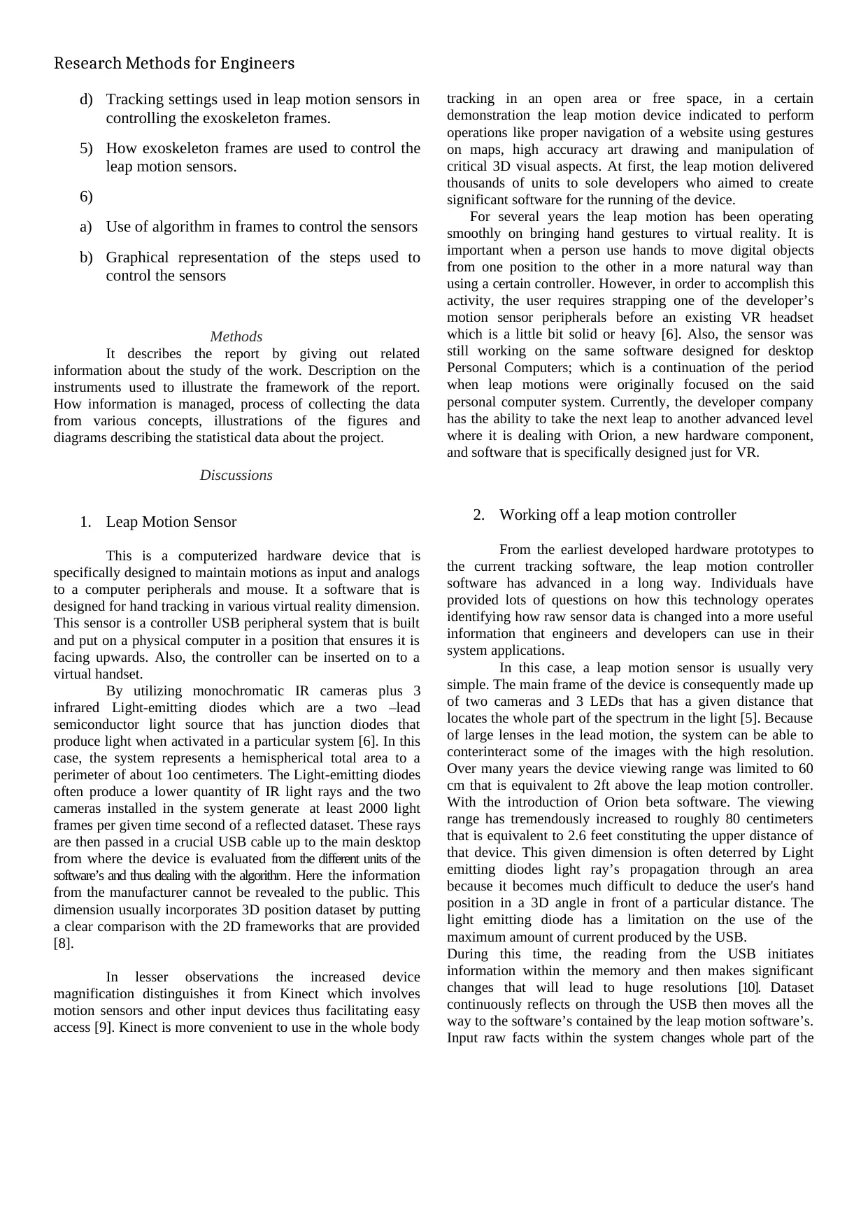
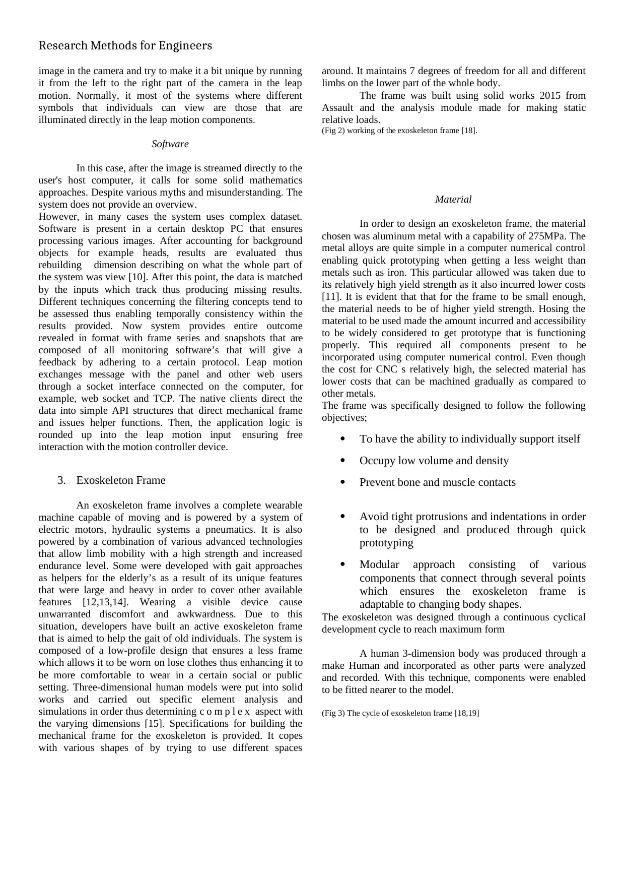
setting. Three-dimensional human models were put into solid
works and carried out specific element analysis and
simulations in order thus determining c o m p l e x aspect with
the varying dimensions [15]. Specifications for building the
mechanical frame for the exoskeleton is provided. It copes
with various shapes of by trying to use different spaces
around. It maintains 7 degrees of freedom for all and different
limbs on the lower part of the whole body.
The frame was built using solid works 2015 from
Assault and the analysis module made for making static
relative loads.
(Fig 2) working of the exoskeleton frame [18].
Material
In order to design an exoskeleton frame, the material
chosen was aluminum metal with a capability of 275MPa. The
metal alloys are quite simple in a computer numerical control
enabling quick prototyping when getting a less weight than
metals such as iron. This particular allowed was taken due to
its relatively high yield strength as it also incurred lower costs
[11]. It is evident that that for the frame to be small enough,
the material needs to be of higher yield strength. Hosing the
material to be used made the amount incurred and accessibility
to be widely considered to get prototype that is functioning
properly. This required all components present to be
incorporated using computer numerical control. Even though
the cost for CNC s relatively high, the selected material has
lower costs that can be machined gradually as compared to
other metals.
The frame was specifically designed to follow the following
objectives;
To have the ability to individually support itself
Occupy low volume and density
Prevent bone and muscle contacts
Avoid tight protrusions and indentations in order
to be designed and produced through quick
prototyping
Modular approach consisting of various
components that connect through several points
which ensures the exoskeleton frame is
adaptable to changing body shapes.
The exoskeleton was designed through a continuous cyclical
development cycle to reach maximum form
A human 3-dimension body was produced through a
make Human and incorporated as other parts were analyzed
and recorded. With this technique, components were enabled
to be fitted nearer to the model.
(Fig 3) The cycle of exoskeleton frame [18,19]
image in the camera and try to make it a bit unique by running
it from the left to the right part of the camera in the leap
motion. Normally, it most of the systems where different
symbols that individuals can view are those that are
illuminated directly in the leap motion components.
Software
In this case, after the image is streamed directly to the
user's host computer, it calls for some solid mathematics
approaches. Despite various myths and misunderstanding. The
system does not provide an overview.
However, in many cases the system uses complex dataset.
Software is present in a certain desktop PC that ensures
processing various images. After accounting for background
objects for example heads, results are evaluated thus
rebuilding dimension describing on what the whole part of
the system was view [10]. After this point, the data is matched
by the inputs which track thus producing missing results.
Different techniques concerning the filtering concepts tend to
be assessed thus enabling temporally consistency within the
results provided. Now system provides entire outcome
revealed in format with frame series and snapshots that are
composed of all monitoring software’s that will give a
feedback by adhering to a certain protocol. Leap motion
exchanges message with the panel and other web users
through a socket interface connected on the computer, for
example, web socket and TCP. The native clients direct the
data into simple API structures that direct mechanical frame
and issues helper functions. Then, the application logic is
rounded up into the leap motion input ensuring free
interaction with the motion controller device.
3. Exoskeleton Frame
An exoskeleton frame involves a complete wearable
machine capable of moving and is powered by a system of
electric motors, hydraulic systems a pneumatics. It is also
powered by a combination of various advanced technologies
that allow limb mobility with a high strength and increased
endurance level. Some were developed with gait approaches
as helpers for the elderly’s as a result of its unique features
that were large and heavy in order to cover other available
features [12,13,14]. Wearing a visible device cause
unwarranted discomfort and awkwardness. Due to this
situation, developers have built an active exoskeleton frame
that is aimed to help the gait of old individuals. The system is
composed of a low-profile design that ensures a less frame
which allows it to be worn on lose clothes thus enhancing it to
be more comfortable to wear in a certain social or public
setting. Three-dimensional human models were put into solid
works and carried out specific element analysis and
simulations in order thus determining c o m p l e x aspect with
the varying dimensions [15]. Specifications for building the
mechanical frame for the exoskeleton is provided. It copes
with various shapes of by trying to use different spaces
around. It maintains 7 degrees of freedom for all and different
limbs on the lower part of the whole body.
The frame was built using solid works 2015 from
Assault and the analysis module made for making static
relative loads.
(Fig 2) working of the exoskeleton frame [18].
Material
In order to design an exoskeleton frame, the material
chosen was aluminum metal with a capability of 275MPa. The
metal alloys are quite simple in a computer numerical control
enabling quick prototyping when getting a less weight than
metals such as iron. This particular allowed was taken due to
its relatively high yield strength as it also incurred lower costs
[11]. It is evident that that for the frame to be small enough,
the material needs to be of higher yield strength. Hosing the
material to be used made the amount incurred and accessibility
to be widely considered to get prototype that is functioning
properly. This required all components present to be
incorporated using computer numerical control. Even though
the cost for CNC s relatively high, the selected material has
lower costs that can be machined gradually as compared to
other metals.
The frame was specifically designed to follow the following
objectives;
To have the ability to individually support itself
Occupy low volume and density
Prevent bone and muscle contacts
Avoid tight protrusions and indentations in order
to be designed and produced through quick
prototyping
Modular approach consisting of various
components that connect through several points
which ensures the exoskeleton frame is
adaptable to changing body shapes.
The exoskeleton was designed through a continuous cyclical
development cycle to reach maximum form
A human 3-dimension body was produced through a
make Human and incorporated as other parts were analyzed
and recorded. With this technique, components were enabled
to be fitted nearer to the model.
(Fig 3) The cycle of exoskeleton frame [18,19]
⊘ This is a preview!⊘
Do you want full access?
Subscribe today to unlock all pages.
Trusted by 1+ million students worldwide
Research Methods for Engineers
4. How Leap motion sensors are used to control
frames.
Leap motion sensors can be handled in different ways
within the exoskeleton frame [19]. Leap motion control panel
application; The leap motion control panel in most it has the
settings, visualizers, and the pause or the resume tracking
device. In setting menu, it helps the user to open the panel in
the motion control which is within the exoskeleton frame. In
visualizer content, there is the launching of the consumer-
oriented visualization application which controls the various
activities while in the resume tracking in most cases it helps to
produce the tracking data within the frame.
There are leap motion sensors features which are used to
control the exoskeleton frames such;
(a) Static gesture features. These are always
constructed depending on the palm and also the
figures with their distances. The distances
between the figures would determine their
capability on how to operate the exoskeleton
frames.
(b) Hand circle features they show how palm is used
in drawing a circle in controlling the exoskeleton
frames. The frames detect the hand and its
responses accordingly. One should ensure the
hand is not rotating when circling within the
exoskeleton frame.
Use of the index swipe and the index key tapping in
controlling the exoskeleton frame. For the two index to operate
exoskeleton frame, clockwise and anticlockwise movements
should be ensured. This boost the control of the frames.
Use of hand interaction. Use of hand to operate the frames is
based on rigid body whereby the first option operating the
exoskeleton determines how to begin and trying to have an
overview of each other. Different shapes such as the use of
cubes are designed to indicate the relationship between the
objects.
Use of the leap motion sensors setting also helps to
control the exoskeleton frame. There are various methods to
tackle these settings within the framework. The following are
various settings in most of the leap motion sensors.
General setting. In the page of there are the following
functions which occur to assist the leap sensors. Helps to
check the allow web box which in overall it opens the web
socket server and thus helping tracking data to apply for the
new applications within the data [24].
Checking on the allow background apps so as to
allow most of the various applications thus can assist in
tracking the overall data in most of the focused application
within the panel. The sensors to help to check the images thus
helping to get the infrared cameras which pose images
contained in the leap motion hardware [34]. When most of the
applications are not checked, they continue to receive most of
the data but the cameras will not be able to get the images as it
is recorded in various frames within the exoskeleton.
Checking on the send usage of data icon as it contains the
statistics in the most of the leap motions. Also, the general
setting contains the check launch in most of the start-up
application this helps to launch the control panel application in
the frames [31].
Tracking settings. It checks on the robust module
thus helping to perform the most of the lighting conditions
within the leap motion [18]. Also, there is need to check the
auto –orient tracking as it gives the axis which helps to detect
most of the views arranged on the opposite sides of the bars
within the exoskeleton frames. The leap motion controller in
most of the cases falls on the lighting parts as it captures the
structured images for at least half a minute.
How leap motion sensor can be interfaced with the
exoskeleton frame
In each of the controller panel, there are frames
which have snapshots. In most cases only hands and also
fingers which are recognized within the senses in frames.
Most frames have the Id values which in many cases they are
skipped when in use. In the computers, the leap motion senses
tend to drop frames which are recorded in most of the
computer software. When this software's detect the robust
mode in order to analyze the IR there are two frames which
are which are discussed that is the frame object and the most
ID which consecutively produced and it always increases by a
factor of two [20].
The leap motion sensors settings are used to control
exoskeleton frames in the following ways;
Getting the data from the frames. Mostly the frame
structures tend to describe the access to data in various frames
[21]. There are various codes which tend to illustrate the
process on how to have the vital objects which are recorded
by the leap motion system within the sensors. Most of the
objects within the frames are always reads the only type of the
object. They are always stored for future use since they tend to
be safe and most of them are encoded using the programming
techniques such as the C++ programming method [22].
Motion which is twice the standard one [23]. When an object
is moved on the screen with adjustments to the hand
movement it means that the move should be maintained
smooth at the same time the sensors will give the history and
also the frames which serve as the functions within the leap
motion panel [23].
Paraphrase This Document
Need a fresh take? Get an instant paraphrase of this document with our AI Paraphraser
Research Methods for Engineers
Using the exoskeleton frame with the call- backs in
the system. At most of the time, listeners are used in the leap
motion frames to give the controller rates [25]. The controller
contains a function which shows when a new frame is
available within the panel. Use of the call-backs tends to be
difficult because they handle a lot of the task per unit time.
Each call-backs contains various threads and therefore being
complex to design and different objects depending on the data
provided by each thread [26,27]. Most of the problems
incurred include the use of the thread and the whole process of
updating some of the objects in the sensors. Therefore, to have
adequate results it means most of the update should be used to
detect threads and too to detect the useful thread within the
panel [28]. Thus it shows that in getting most of the leap
motion sensors data is always the same as getting the polling
controller.
By following the object or the entities across the
exoskeleton frames. If the system has the ID for the frame,
then it means there must be an object that stands for the
frames. The appropriate function will be detected. If it
happens that the code cannot be detected there is the return of
the special object or key to the system within the exoskeleton
frames [29].
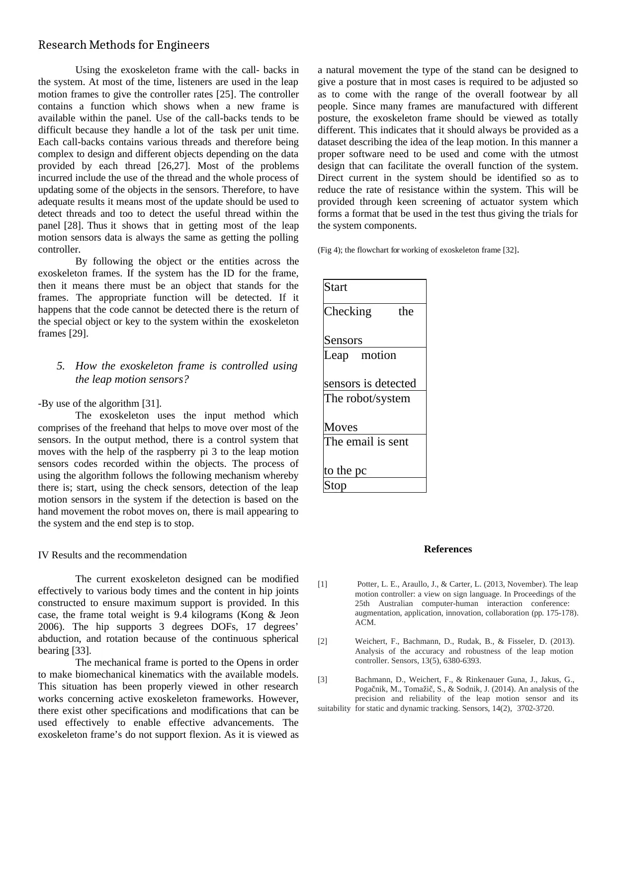
5. How the exoskeleton frame is controlled using
the leap motion sensors?
-By use of the algorithm [31].
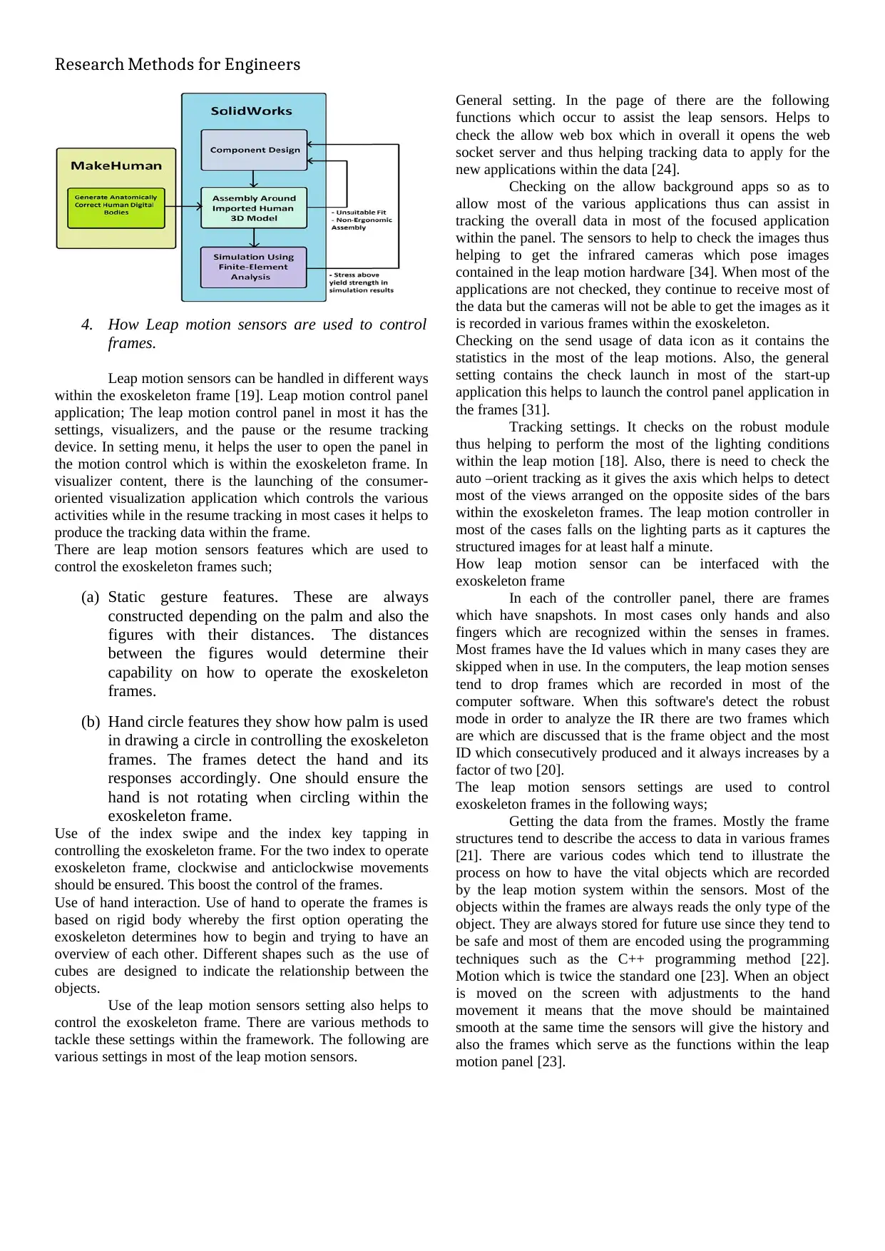
The exoskeleton uses the input method which
comprises of the freehand that helps to move over most of the
sensors. In the output method, there is a control system that
moves with the help of the raspberry pi 3 to the leap motion
sensors codes recorded within the objects. The process of
using the algorithm follows the following mechanism whereby
there is; start, using the check sensors, detection of the leap
motion sensors in the system if the detection is based on the
hand movement the robot moves on, there is mail appearing to
the system and the end step is to stop.
IV Results and the recommendation
The current exoskeleton designed can be modified
effectively to various body times and the content in hip joints
constructed to ensure maximum support is provided. In this
case, the frame total weight is 9.4 kilograms (Kong & Jeon
2006). The hip supports 3 degrees DOFs, 17 degrees’
abduction, and rotation because of the continuous spherical
bearing [33].
The mechanical frame is ported to the Opens in order
to make biomechanical kinematics with the available models.
This situation has been properly viewed in other research
works concerning active exoskeleton frameworks. However,
there exist other specifications and modifications that can be
used effectively to enable effective advancements. The
exoskeleton frame’s do not support flexion. As it is viewed as
a natural movement the type of the stand can be designed to
give a posture that in most cases is required to be adjusted so
as to come with the range of the overall footwear by all
people. Since many frames are manufactured with different
posture, the exoskeleton frame should be viewed as totally
different. This indicates that it should always be provided as a
dataset describing the idea of the leap motion. In this manner a
proper software need to be used and come with the utmost
design that can facilitate the overall function of the system.
Direct current in the system should be identified so as to
reduce the rate of resistance within the system. This will be
provided through keen screening of actuator system which
forms a format that be used in the test thus giving the trials for
the system components.
(Fig 4); the flowchart for working of exoskeleton frame [32].
Start
Checking the
Sensors
Leap motion
sensors is detected
The robot/system
Moves
The email is sent
to the pc
Stop
References
[1] Potter, L. E., Araullo, J., & Carter, L. (2013, November). The leap
motion controller: a view on sign language. In Proceedings of the
25th Australian computer-human interaction conference:
augmentation, application, innovation, collaboration (pp. 175-178).
ACM.
[2] Weichert, F., Bachmann, D., Rudak, B., & Fisseler, D. (2013).
Analysis of the accuracy and robustness of the leap motion
controller. Sensors, 13(5), 6380-6393.
[3] Bachmann, D., Weichert, F., & Rinkenauer Guna, J., Jakus, G.,
Pogačnik, M., Tomažič, S., & Sodnik, J. (2014). An analysis of the
precision and reliability of the leap motion sensor and its
suitability for static and dynamic tracking. Sensors, 14(2), 3702-3720.
Using the exoskeleton frame with the call- backs in
the system. At most of the time, listeners are used in the leap
motion frames to give the controller rates [25]. The controller
contains a function which shows when a new frame is
available within the panel. Use of the call-backs tends to be
difficult because they handle a lot of the task per unit time.
Each call-backs contains various threads and therefore being
complex to design and different objects depending on the data
provided by each thread [26,27]. Most of the problems
incurred include the use of the thread and the whole process of
updating some of the objects in the sensors. Therefore, to have
adequate results it means most of the update should be used to
detect threads and too to detect the useful thread within the
panel [28]. Thus it shows that in getting most of the leap
motion sensors data is always the same as getting the polling
controller.
By following the object or the entities across the
exoskeleton frames. If the system has the ID for the frame,
then it means there must be an object that stands for the
frames. The appropriate function will be detected. If it
happens that the code cannot be detected there is the return of
the special object or key to the system within the exoskeleton
frames [29].
5. How the exoskeleton frame is controlled using
the leap motion sensors?
-By use of the algorithm [31].
The exoskeleton uses the input method which
comprises of the freehand that helps to move over most of the
sensors. In the output method, there is a control system that
moves with the help of the raspberry pi 3 to the leap motion
sensors codes recorded within the objects. The process of
using the algorithm follows the following mechanism whereby
there is; start, using the check sensors, detection of the leap
motion sensors in the system if the detection is based on the
hand movement the robot moves on, there is mail appearing to
the system and the end step is to stop.
IV Results and the recommendation
The current exoskeleton designed can be modified
effectively to various body times and the content in hip joints
constructed to ensure maximum support is provided. In this
case, the frame total weight is 9.4 kilograms (Kong & Jeon
2006). The hip supports 3 degrees DOFs, 17 degrees’
abduction, and rotation because of the continuous spherical
bearing [33].
The mechanical frame is ported to the Opens in order
to make biomechanical kinematics with the available models.
This situation has been properly viewed in other research
works concerning active exoskeleton frameworks. However,
there exist other specifications and modifications that can be
used effectively to enable effective advancements. The
exoskeleton frame’s do not support flexion. As it is viewed as
a natural movement the type of the stand can be designed to
give a posture that in most cases is required to be adjusted so
as to come with the range of the overall footwear by all
people. Since many frames are manufactured with different
posture, the exoskeleton frame should be viewed as totally
different. This indicates that it should always be provided as a
dataset describing the idea of the leap motion. In this manner a
proper software need to be used and come with the utmost
design that can facilitate the overall function of the system.
Direct current in the system should be identified so as to
reduce the rate of resistance within the system. This will be
provided through keen screening of actuator system which
forms a format that be used in the test thus giving the trials for
the system components.
(Fig 4); the flowchart for working of exoskeleton frame [32].
Start
Checking the
Sensors
Leap motion
sensors is detected
The robot/system
Moves
The email is sent
to the pc
Stop
References
[1] Potter, L. E., Araullo, J., & Carter, L. (2013, November). The leap
motion controller: a view on sign language. In Proceedings of the
25th Australian computer-human interaction conference:
augmentation, application, innovation, collaboration (pp. 175-178).
ACM.
[2] Weichert, F., Bachmann, D., Rudak, B., & Fisseler, D. (2013).
Analysis of the accuracy and robustness of the leap motion
controller. Sensors, 13(5), 6380-6393.
[3] Bachmann, D., Weichert, F., & Rinkenauer Guna, J., Jakus, G.,
Pogačnik, M., Tomažič, S., & Sodnik, J. (2014). An analysis of the
precision and reliability of the leap motion sensor and its
suitability for static and dynamic tracking. Sensors, 14(2), 3702-3720.
Research Methods for Engineers
[4] Lu, W., Tong, Z., & Chu, J. (2016). Dynamic hand gesture
recognition with leap motion controller. IEEE Signal Processing
Letters, 23(9), 1188-1192.
[5] Bortole, M., Venkatakrishnan, A., Zhu, F., Moreno, J. C.,
Francisco, G. E., Pons, J. L., & Contreras-Vidal, J. L. (2015). The H2 robotic
exoskeleton for gait rehabilitation after stroke: early findings from
a clinical study. Journal of neuroengineering and rehabilitation,
12(1), 54.
[6] Fontana, M., Dettori, A., Salsedo, F., & Bergamasco, M. (2009,
May). Mechanical design of a novel hand exoskeleton for accurate
force displaying. In Robotics and Automation, 2009. ICRA'09.
IEEE International Conference on (pp. 1704- 1709). IEEE.
[7] Kong, K., & Jeon, D. (2006). Design and control of an exoskeleton
for the elderly and patients. IEEE/ASME Transactions on
mechatronics, 11(4), 428-432.
[8] Lagoda, C., Schouten, A. C., Stienen, A. H., Hekman, E. E., & van
der Kooij, H. (2010, September). Design of an electric series elastic
actuated joint for robotic gait rehabilitation training. In Biomedical
Robotics and Biomechatronics (BioRob), 2010 3rd IEEE RAS and
EMBS International Conference on (pp. 21-26). IEEE.
[9] Murray, S. A., Ha, K. H., Hartigan, C., & Goldfarb, M. (2015). An
assistive control approach for a lower-limb exoskeleton to facilitate
recovery of walking following stroke. IEEE Transactions on
Neural Systems and
Rehabilitation Engineering, 23(3), 441-449.
[10] Coelho, J. C., & Verbeek, F. J. (2014). Pointing task evaluation of
leap motion controller in 3D virtual environment.
Creating the Difference, 78, 78-85.
[11] Tung, J. Y., Lulic, T., Gonzalez, D. A.,Tran, J., Dickerson, C. R.,
& Roy, E. A. (2015). Evaluation of a portable markerless finger
position capture device: accuracy of the Leap Motion controller in
healthy adults. Physiological measurement, 36(5), 1025.
[12] Smeragliuolo, A. H., Hill, N. J., Disla, L., & Putrino, D. (2016).
Validation of the Leap Motion Controller using markered motion
capture technology. Journal of biomechanics, 49(9), 1742-1750.
[13] Chuan, C. H., Regina, E., & Guardino, C. (2014, December).
American sign language recognition using leap motion sensor.
In Machine Learning and Applications (ICMLA), 2014 13th
International Conference on (pp. 541-544). IEEE.
[14] Marin, G., Dominio, F., & Zanuttigh, P. (2016). Hand gesture
recognition with jointly calibrated leap motion and depth sensor.
Multimedia Tools and Applications, 75(22), 14991-15015.
[15] Liu, H., Wei, X., Chai, J., Ha, I., & Rhee, T. (2011, February).
Real- time human motion control with a small number of inertial sensors.
In Symposium on Interactive 3D Graphics and Games (pp. 133-
140). ACM.
[16] Cui, J., & Sourin, A. (2014, October). Feasibility study on
freehand geometric modeling using leap motion in VRML/X3D. In
Cyberworlds (CW), 2014 International Conference on (pp. 389-
392). IEEE.
[17] Du, G., Zhang, P., & Liu, X. (2016).
Markerless Human–Manipulator Interface Using Leap Motion
With Interval Kalman Filter and Improved Particle Filter. IEEE
Transactions on Industrial Informatics, 12(2), 694-704.
[18] Du, G., & Zhang, P. (2015). A markerless human-robot interface
using particle filter and Kalman filter for dual robots. IEEE
Transactions on Industrial Electronics, 62(4), 2257-2264.
Burdea, G. C., Cioi, D., Kale, A., Janes, W.
[19] E., Ross, S. A., & Engsberg, J. R. (2013). Robotics and gaming to
improve ankle strength, motor control, and function in children
with cerebral palsy—a case study series. IEEE Transactions on Neural
Systems and Rehabilitation Engineering, 21(2), 165-173.
[20] Petrič, T., Gams, A., Debevec, T., Žlajpah, L., & Babič, J. (2013).
Advanced Robotics, 27(13), 993-1002.
[21] Young, A. J., & Ferris, D. P. (2017). State of the art and future
directions for lower limb robotic exoskeletons. IEEE Transactions
on Neural Systems and Rehabilitation Engineering, 25(2), 171-
[22] Field, M., Pan, Z., Stirling, D., & Naghdy, F. (2011). Human
motion capture sensors and analysis in robotics. Industrial Robot: An
International Journal, 38(2), 163-171.
[23] De Vito, L., Postolache, O., & Rapuano, S. (2014). Measurements
and sensors for motion tracking in motor rehabilitation.
[24] Savatekar, M. R. D., & Dum, M. A. (2016). Design Of Control
System For Articulated Robot Using Leap Motion Sensor.
[25] Yang, C., Chen, J., & Chen, F. (2016, September). Neural learning
enhanced teleoperation control of Baxter robot using IMU based
motion capture. In Automation and Computing (ICAC), 2016 22nd
International Conference on (pp. 389-394). IEEE.
[26] Shi, G., Wang, Y., & Li, S. (2014). Human Motion Capture
System and its Sensor Analysis. Sensors & Transducers,
172(6), 206.
[27] Y., Jo, I., Lee, J., & Bae, J. (2017,
September). A wearable hand system for virtual reality. In
Intelligent Robots and Systems (IROS), 2017 IEEE/RSJ
International Conference on (pp. 1052- 1057). IEEE.
[28 ]Dobins, M. K., Rondot, P., Schwartz, K., Shone, E. D., Yokell, M.
R., Abshire, K. J.,... & Lovell, S. (2012). U.S. Patent No.
8,217,995. Washington, DC: U.S. Patent and Trademark Office.
[29 ]Parietti, F., Chan, K. C., Hunter, B., & Asada, H. H. (2015, May).
Design and control of supernumerary robotic limbs for balance
augmentation. In Robotics and Automation (ICRA), 2015 IEEE
International Conference on IEEE (pp. 5010-5017)
[30] Cao, H., Ling, Z., Zhu, J., Wang, Y., & Wang, W. (2009,
December). Design frame of a leg exoskeleton for load-carrying
augmentation. In Robotics and Biomimetics (ROBIO), 2009 IEEE
International Conference on (pp. 426-431). IEEE.
[31] Lagoda, C., A wearable hand system for virtual reality. In
Intelligent Robots and Systems (IROS), 2017
[ 3 2 ] Shi, G., Wang, Y., & Li, S. (20150 Industrial Robot: An
International Journal, 38(2), 163-171.
[33] Field, M., Pan, Z., Stirling, D., & Naghdy, F. (2011). . (2016).
Design Of Control System For Articulated Robot Using Leap
Motion Sensor.
[34] Shi, G .(2015, May). Design and control of supernumerary robotic
limbs for balance augmentation.
⊘ This is a preview!⊘
Do you want full access?
Subscribe today to unlock all pages.
Trusted by 1+ million students worldwide
1 out of 6
Related Documents


Your All-in-One AI-Powered Toolkit for Academic Success.
+13062052269
info@desklib.com
Available 24*7 on WhatsApp / Email
![[object Object]](/_next/static/media/star-bottom.7253800d.svg)
Unlock your academic potential
Copyright © 2020–2026 A2Z Services. All Rights Reserved. Developed and managed by ZUCOL.