Surveying Practical Report: Levelling and Traversing in Construction
VerifiedAdded on 2023/06/15
|20
|3405
|493
Practical Assignment
AI Summary
This practical report details surveying exercises involving leveling and traversing techniques. The leveling exercise aimed to create a contour drawing of a block of land, analyzing spot heights and topographic features, using equipment like an automatic level and tripod. The report includes the methodology, original and completed booking sheets, a contour drawing, and a discussion of potential errors. The traversing exercise involved two tasks: comparing observed and mathematically derived bearings and distances using a theodolite, chain, and tape. Task 1 focused on measuring building dimensions, while Task 2 involved completing a traverse and calculating misclosure distance and ratio. The report discusses potential errors and compares the accuracy of different measurement methods. Desklib offers a variety of similar reports and study resources for students.
Surveying Practical Report 1
SURVEYING PRACTICAL REPORT
By [Name]
Course
Professor’s Name
Institution
Location of Institution
Date
SURVEYING PRACTICAL REPORT
By [Name]
Course
Professor’s Name
Institution
Location of Institution
Date
Paraphrase This Document
Need a fresh take? Get an instant paraphrase of this document with our AI Paraphraser
Surveying Practical Report 2
Contents
Practical 1: Levelling.......................................................................................................................3
1.0 Introduction...........................................................................................................................3
1.1 Aim.........................................................................................................................................3
1.2 Equipment..............................................................................................................................3
1.3 Method...................................................................................................................................4
1.4 Booking Sheet (Original).......................................................................................................5
1.5 Booking Sheet (Completed)...................................................................................................6
1.6 Contour D3rawing.................................................................................................................9
1.7 Discussion............................................................................................................................10
Practical 2: Traversing...................................................................................................................10
2.0 Introduction.........................................................................................................................10
2.1T ask 1...................................................................................................................................11
Aim.........................................................................................................................................11
Equipment..............................................................................................................................11
Method...................................................................................................................................11
Results....................................................................................................................................13
Discussion..............................................................................................................................13
2.2 Task 2...................................................................................................................................14
Aim.........................................................................................................................................14
Equipment..............................................................................................................................14
Method...................................................................................................................................14
Results....................................................................................................................................15
Misclosure Distance..............................................................................................................16
Misclosure Ratio....................................................................................................................17
Discussion..............................................................................................................................17
Surveying Practical Report 3
Practical 1: Levelling
1.0 Introduction
Levelling is a surveying procedure that is used to determine the relative height of a point to
another (Basak, 2014). The technique is applied in major survey and construction projects to
establish the elevation of points relative to a datum(s), or to locate a point at a given elevation
relative to a datum. The method applied in leveling to detect elevation variations and elevation
points is called the rise and fall method. The main instrument used to carry out leveling is called
a level. There are many types of levels including dumpy, laser, tilting, digital and automatic
levels. The principle leveling methods include spirit leveling, barometric leveling and
trigonometric leveling.
1.1 Aim
The aim of the leveling practical was to portray a countered drawing of a ‘block of land’
survey.
An analysis of all the spot heights (external and internal) to the ‘block of land’ was done and
as a result the drawing done. Also, the practical’s objective was to describe the topographic
features encountered on the block of land using the contours that were to be drawn on the
contour drawing.
1.2 Equipment
The following are the equipment used to carry out the practical:
1. A Tripod
2. An automatic level. Serial number:________________________
3. A staff
4. A tape measure
⊘ This is a preview!⊘
Do you want full access?
Subscribe today to unlock all pages.
Trusted by 1+ million students worldwide
Surveying Practical Report 4
5. A leveling bubble and,
6. A clip board.
1.3 Method
1. First, a bench mark (BM) for carrying out the practical was established.
2. The equipment (automatic level) was set up outside the ‘block of land’ in a position
where the BM could be clearly shot. The procedure for setting up the equipment was as follows:
i. The tripod legs were spread so that the tripod head is approximately level and at a
height where the observe could comfortably make observations.
ii. A check was done to the leg screws to ensure they are finger tight after treading the
tripod legs into the ground.
iii. The level was then mounted on the head and screwed into position.
iv. The circular bubble was centralized using the foot screws and ensure the equipment is
set accurately for use.
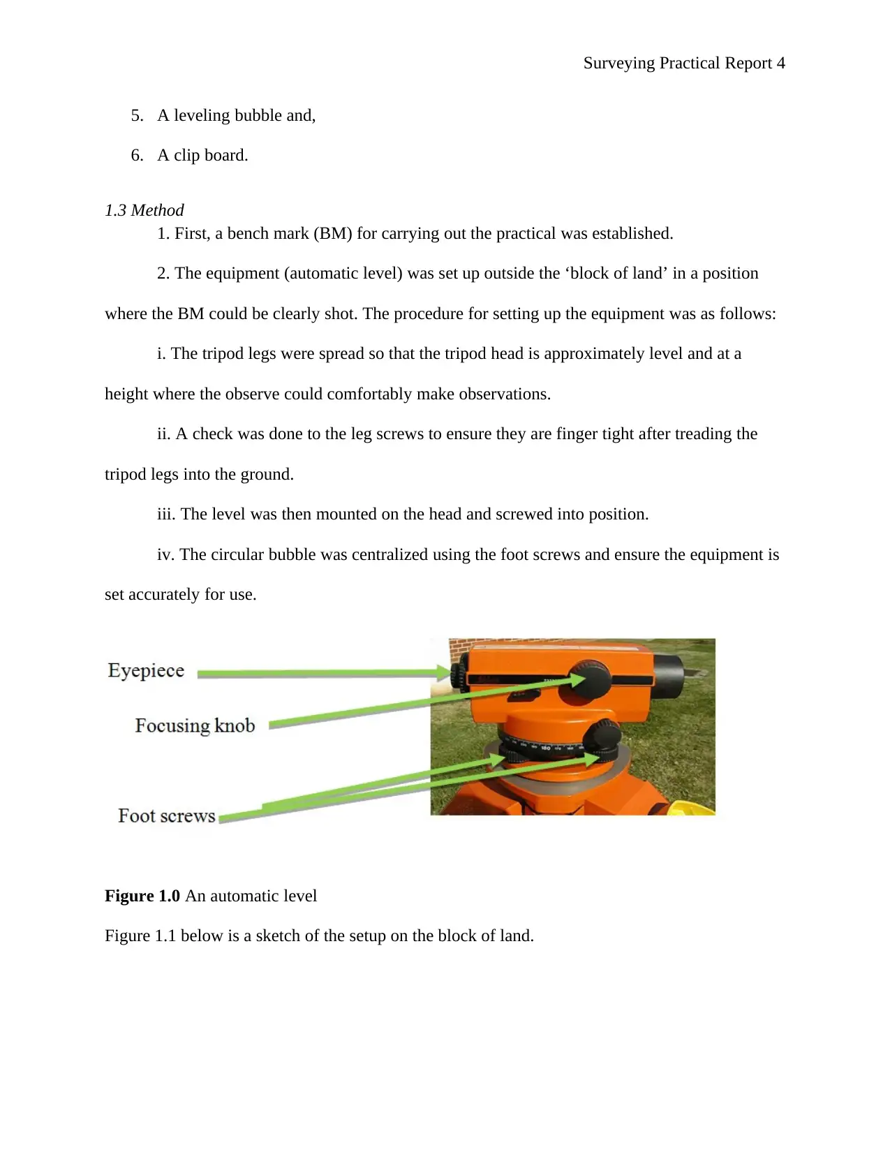
Figure 1.0 An automatic level
Figure 1.1 below is a sketch of the setup on the block of land.
5. A leveling bubble and,
6. A clip board.
1.3 Method
1. First, a bench mark (BM) for carrying out the practical was established.
2. The equipment (automatic level) was set up outside the ‘block of land’ in a position
where the BM could be clearly shot. The procedure for setting up the equipment was as follows:
i. The tripod legs were spread so that the tripod head is approximately level and at a
height where the observe could comfortably make observations.
ii. A check was done to the leg screws to ensure they are finger tight after treading the
tripod legs into the ground.
iii. The level was then mounted on the head and screwed into position.
iv. The circular bubble was centralized using the foot screws and ensure the equipment is
set accurately for use.
Figure 1.0 An automatic level
Figure 1.1 below is a sketch of the setup on the block of land.
Paraphrase This Document
Need a fresh take? Get an instant paraphrase of this document with our AI Paraphraser
A B C D E F
1
2
3
4
5
6
Block of land
BM
F6
A1
Surveying Practical Report 5
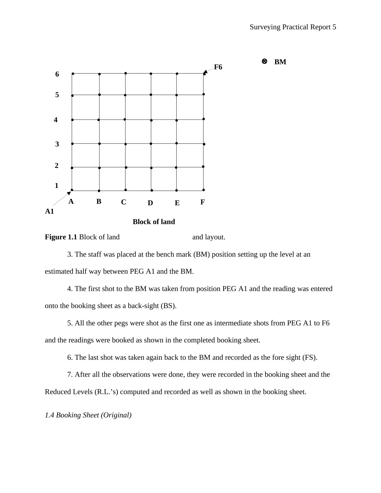
Figure 1.1 Block of land and layout.
3. The staff was placed at the bench mark (BM) position setting up the level at an
estimated half way between PEG A1 and the BM.
4. The first shot to the BM was taken from position PEG A1 and the reading was entered
onto the booking sheet as a back-sight (BS).
5. All the other pegs were shot as the first one as intermediate shots from PEG A1 to F6
and the readings were booked as shown in the completed booking sheet.
6. The last shot was taken again back to the BM and recorded as the fore sight (FS).
7. After all the observations were done, they were recorded in the booking sheet and the
Reduced Levels (R.L.’s) computed and recorded as well as shown in the booking sheet.
1.4 Booking Sheet (Original)
1
2
3
4
5
6
Block of land
BM
F6
A1
Surveying Practical Report 5
Figure 1.1 Block of land and layout.
3. The staff was placed at the bench mark (BM) position setting up the level at an
estimated half way between PEG A1 and the BM.
4. The first shot to the BM was taken from position PEG A1 and the reading was entered
onto the booking sheet as a back-sight (BS).
5. All the other pegs were shot as the first one as intermediate shots from PEG A1 to F6
and the readings were booked as shown in the completed booking sheet.
6. The last shot was taken again back to the BM and recorded as the fore sight (FS).
7. After all the observations were done, they were recorded in the booking sheet and the
Reduced Levels (R.L.’s) computed and recorded as well as shown in the booking sheet.
1.4 Booking Sheet (Original)
Surveying Practical Report 6
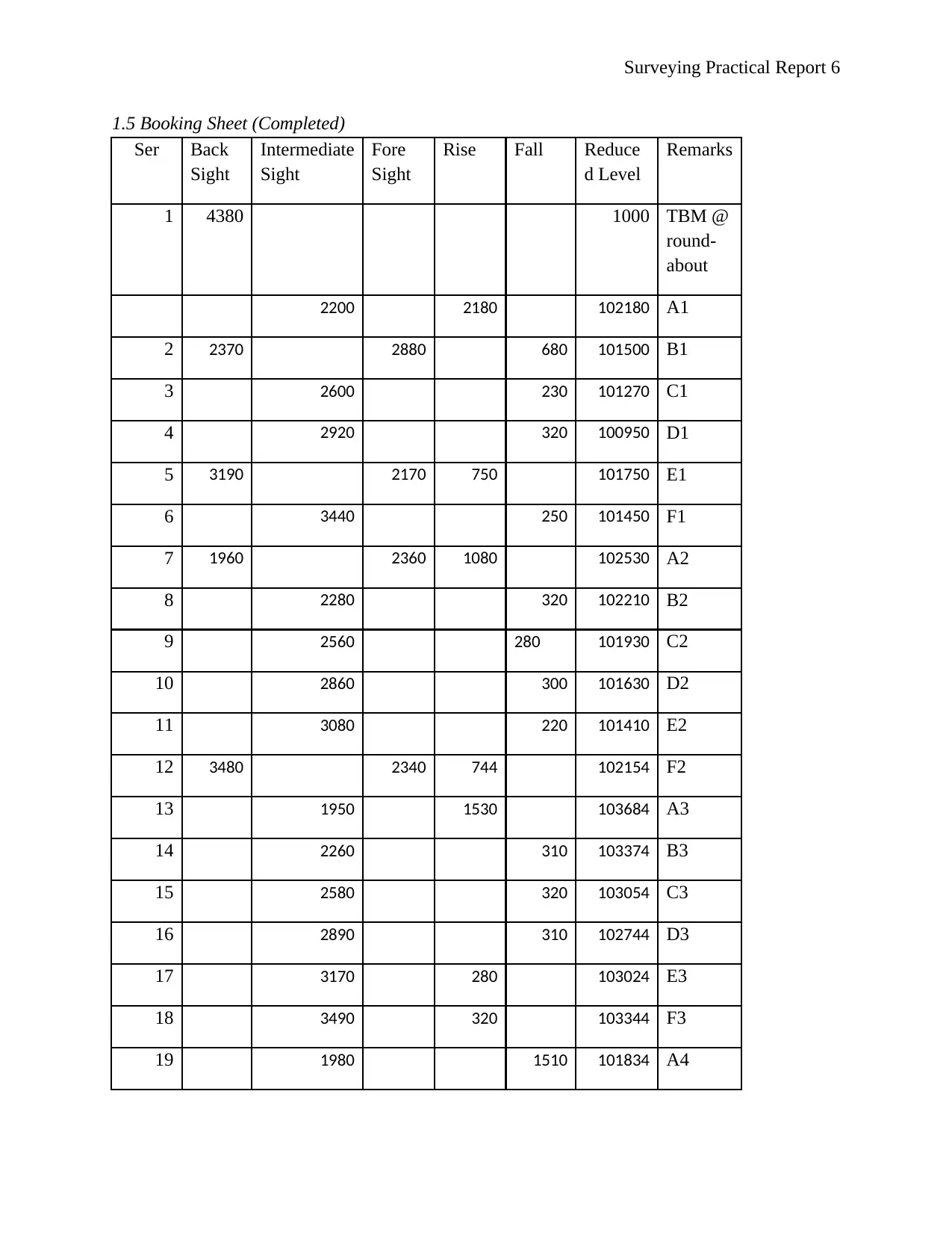
1.5 Booking Sheet (Completed)
Ser Back
Sight
Intermediate
Sight
Fore
Sight
Rise Fall Reduce
d Level
Remarks
1 4380 1000 TBM @
round-
about
2200 2180 102180 A1
2 2370 2880 680 101500 B1
3 2600 230 101270 C1
4 2920 320 100950 D1
5 3190 2170 750 101750 E1
6 3440 250 101450 F1
7 1960 2360 1080 102530 A2
8 2280 320 102210 B2
9 2560 280 101930 C2
10 2860 300 101630 D2
11 3080 220 101410 E2
12 3480 2340 744 102154 F2
13 1950 1530 103684 A3
14 2260 310 103374 B3
15 2580 320 103054 C3
16 2890 310 102744 D3
17 3170 280 103024 E3
18 3490 320 103344 F3
19 1980 1510 101834 A4
⊘ This is a preview!⊘
Do you want full access?
Subscribe today to unlock all pages.
Trusted by 1+ million students worldwide
Surveying Practical Report 7
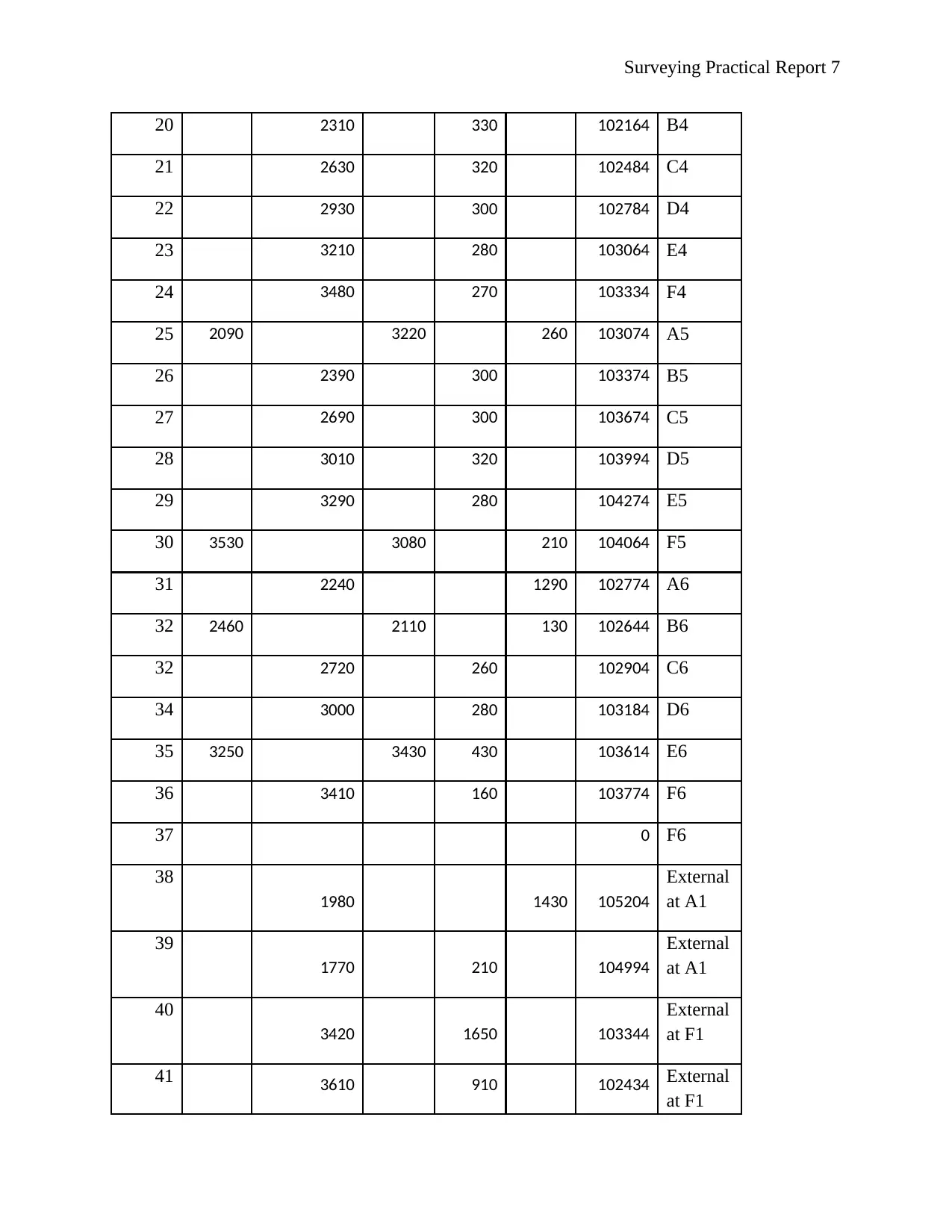
20 2310 330 102164 B4
21 2630 320 102484 C4
22 2930 300 102784 D4
23 3210 280 103064 E4
24 3480 270 103334 F4
25 2090 3220 260 103074 A5
26 2390 300 103374 B5
27 2690 300 103674 C5
28 3010 320 103994 D5
29 3290 280 104274 E5
30 3530 3080 210 104064 F5
31 2240 1290 102774 A6
32 2460 2110 130 102644 B6
32 2720 260 102904 C6
34 3000 280 103184 D6
35 3250 3430 430 103614 E6
36 3410 160 103774 F6
37 0 F6
38
1980 1430 105204
External
at A1
39
1770 210 104994
External
at A1
40
3420 1650 103344
External
at F1
41 3610 910 102434 External
at F1
Paraphrase This Document
Need a fresh take? Get an instant paraphrase of this document with our AI Paraphraser
Surveying Practical Report 8
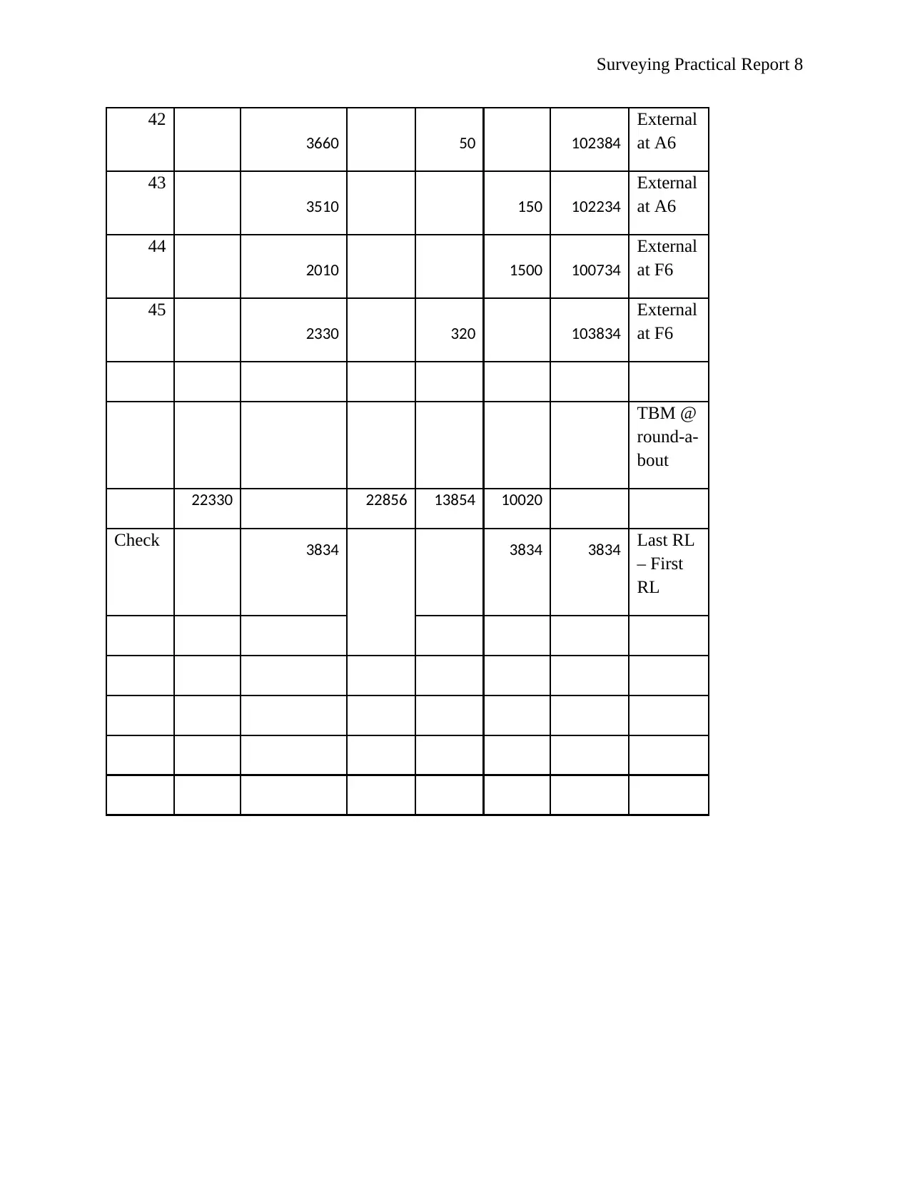
42
3660 50 102384
External
at A6
43
3510 150 102234
External
at A6
44
2010 1500 100734
External
at F6
45
2330 320 103834
External
at F6
TBM @
round-a-
bout
22330 22856 13854 10020
Check 3834 3834 3834 Last RL
– First
RL
42
3660 50 102384
External
at A6
43
3510 150 102234
External
at A6
44
2010 1500 100734
External
at F6
45
2330 320 103834
External
at F6
TBM @
round-a-
bout
22330 22856 13854 10020
Check 3834 3834 3834 Last RL
– First
RL
Surveying Practical Report 9
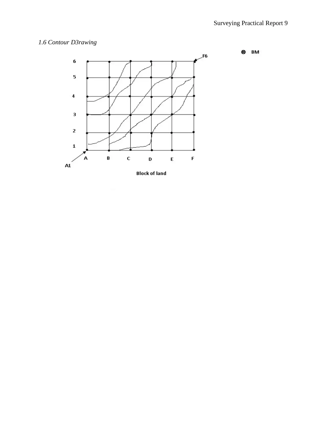
1.6 Contour D3rawing
1.6 Contour D3rawing
⊘ This is a preview!⊘
Do you want full access?
Subscribe today to unlock all pages.
Trusted by 1+ million students worldwide
Surveying Practical Report 10
1.7 Discussion
After computation of the Rises, fall and Reduced Levels, the Reduced Levels were used
to sketch a contour map as shown. Contours are imaginary lines drawn on a topographical map
joining surfaces with the same elevation. In this practical, contour points were located and then
used to draw smooth contour lines that connect corresponding points on surfaces on the ‘block of
land.’
The accuracy in the survey was a gross misclose of 18 mm. The value shows that they
experiment were done with high precision. Values diverting so much from the actual
measurements indicate that there were errors during the practical. The value of accuracy obtained
for this practical was not exactly what is expected because of errors due to various factors.
Probable causes of errors during the experiment include instrumental errors. Instrumental
errors could have resulted due to imperfect adjustment, the tripod was shaking, and the level tube
could have been defective or incorrect graduations on the staff. Errors due to manipulation
including careless leveling-up of the instrument, the bubble was not central at the time of taking
the reading, parallax, or the staff was not held vertical. Lastly, natural causes such as wind and
the sun might have made it difficult to carry out the experiment (ConcreteCivil, 2017).
Practical 2: Traversing
2.0 Introduction
Traversing is a field survey method that is used in the establishment of control networks.
The survey procedure is also used in geodesy. In traversing, several connected survey lines form
a framework. A tape or chain, and an angle measuring instrument is used to measure the lengths
and the directions of the survey lines. There are types of traverse surveying; the closed traverse,
Paraphrase This Document
Need a fresh take? Get an instant paraphrase of this document with our AI Paraphraser
Surveying Practical Report 11
and the open traverse. In the former, lines form a circuit that ends where the traverse began,
whereas in the latter, lines forming the traverse end somewhere else other than the starting point
(Schofield, 2013).
2.1T ask 1
Aim
The aim of the practical was to compare the final bearing and distance to close a traverse
as it was observed in the field against the bearing and distance that was derived mathematically.
Equipment
1. Theodolite
2. Chain
3. Tape
4. Ranging rods
5. Arrows
6. Cross staff
Method
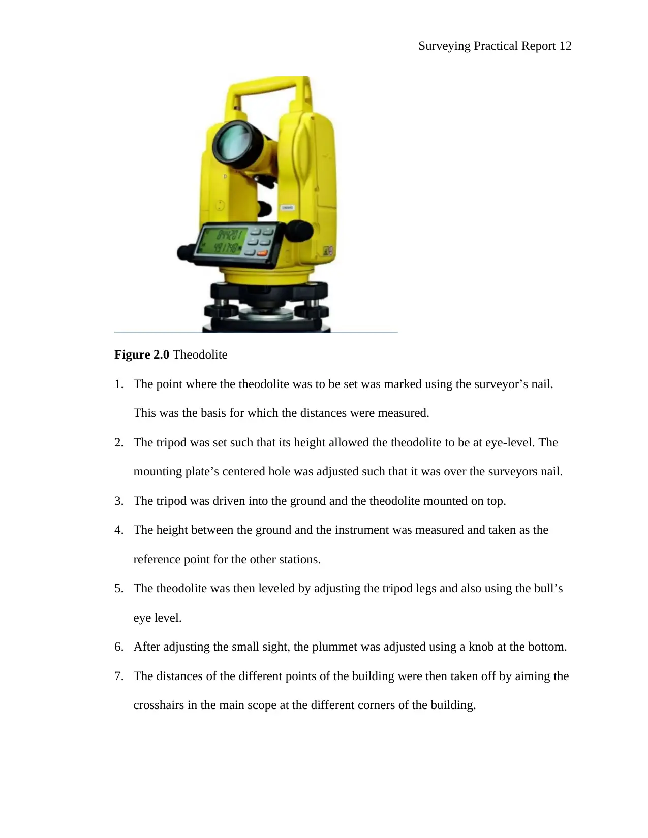
The instrument that is used for traversing is the theodolite. The theodolite measures both
vertical and horizontal angles. Vertical angles are used for the calculation of the elevation of
point’s e.g the reduction of slope distance to the horizontal, while the horizontal angles are used
to find the relative direction of a survey control station. The traversing instrument is the most
accurate as it gives an accuracy of up to 1”. It has a telescope that can be used to sight distance
objects. A theodolite can be optical or electronic digital.
and the open traverse. In the former, lines form a circuit that ends where the traverse began,
whereas in the latter, lines forming the traverse end somewhere else other than the starting point
(Schofield, 2013).
2.1T ask 1
Aim
The aim of the practical was to compare the final bearing and distance to close a traverse
as it was observed in the field against the bearing and distance that was derived mathematically.
Equipment
1. Theodolite
2. Chain
3. Tape
4. Ranging rods
5. Arrows
6. Cross staff
Method
The instrument that is used for traversing is the theodolite. The theodolite measures both
vertical and horizontal angles. Vertical angles are used for the calculation of the elevation of
point’s e.g the reduction of slope distance to the horizontal, while the horizontal angles are used
to find the relative direction of a survey control station. The traversing instrument is the most
accurate as it gives an accuracy of up to 1”. It has a telescope that can be used to sight distance
objects. A theodolite can be optical or electronic digital.
Surveying Practical Report 12
Figure 2.0 Theodolite
1. The point where the theodolite was to be set was marked using the surveyor’s nail.
This was the basis for which the distances were measured.
2. The tripod was set such that its height allowed the theodolite to be at eye-level. The
mounting plate’s centered hole was adjusted such that it was over the surveyors nail.
3. The tripod was driven into the ground and the theodolite mounted on top.
4. The height between the ground and the instrument was measured and taken as the
reference point for the other stations.
5. The theodolite was then leveled by adjusting the tripod legs and also using the bull’s
eye level.
6. After adjusting the small sight, the plummet was adjusted using a knob at the bottom.
7. The distances of the different points of the building were then taken off by aiming the
crosshairs in the main scope at the different corners of the building.
⊘ This is a preview!⊘
Do you want full access?
Subscribe today to unlock all pages.
Trusted by 1+ million students worldwide
1 out of 20

Your All-in-One AI-Powered Toolkit for Academic Success.
+13062052269
info@desklib.com
Available 24*7 on WhatsApp / Email
![[object Object]](/_next/static/media/star-bottom.7253800d.svg)
Unlock your academic potential
Copyright © 2020–2026 A2Z Services. All Rights Reserved. Developed and managed by ZUCOL.