Light Detecting Robot Project - IUM Engineering CE3 Report
VerifiedAdded on 2022/10/31
|8
|1608
|173
Report
AI Summary
This report details a student's Career Episode 3 (CE3) project on a light-detecting robot, undertaken at the Islamic University Malaysia (IUM). The project involved designing and building a robot with four tires capable of detecting light sources and navigating towards them, utilizing an Arduino controller, LDR (Light Dependent Resistor) sensors, and ultrasonic sensors. The student, acting as the team leader, describes the project background, objectives, and their specific area of work, which included programming in C, implementing sensor systems, and utilizing leadership skills. The report highlights the engineering knowledge applied, including calculations of light intensity, and skills in assembling the robot. The student also identifies issues such as sensor calibration differences and proposes solutions such as using the demonstrator to steer based on light intensity and avoid obstacles based on color coding. The report concludes with a project overview, emphasizing the student's contribution to the project's success and the application of production engineering skills.

Competency Demonstration Report
Career Episode 3
Career Episode 3
Paraphrase This Document
Need a fresh take? Get an instant paraphrase of this document with our AI Paraphraser
CE 3.1 Project Information
Name of the project: Light detecting robot
Location of the project: Gombak, Malaysia
Project Duration: 2months
Organization: Islamic University Malaysia
Role and Designation during the time: Team Leader
CE 3.2 Project Background
CE 3.2.1 Characteristics of the project
The project is based on assembling a robot with 4 tires for detecting lights as well as
moves towards it. The sensor as well as control system is a part of proposed robot platform. It
is used to provide flexible as well as modular system to control movement of robot, retrieve
the sensor data related to surroundings plus prevention of collisions. The sensor system is
used to work in parallel with vision system so that it can provide information for taking
decisions. I used open source Arduino platform for controlling and contributing to make
usage of the sensors easier. I used code for reading filter sensor values such as red, green, and
blue as well as calculation of lux plus colour temperature. I focused on testing as well as
confirming output from sensor for determining sense range and sample frequency which can
negotiate between accuracy as well as breaking distance.
CE 3.2.2 Objectives developed for the project
While executing the project related to light detecting robot, I achieved accuracy of the
robot and designing different technologies as well as tools. In order to complete the work on
time, following are list of the project objectives such as:
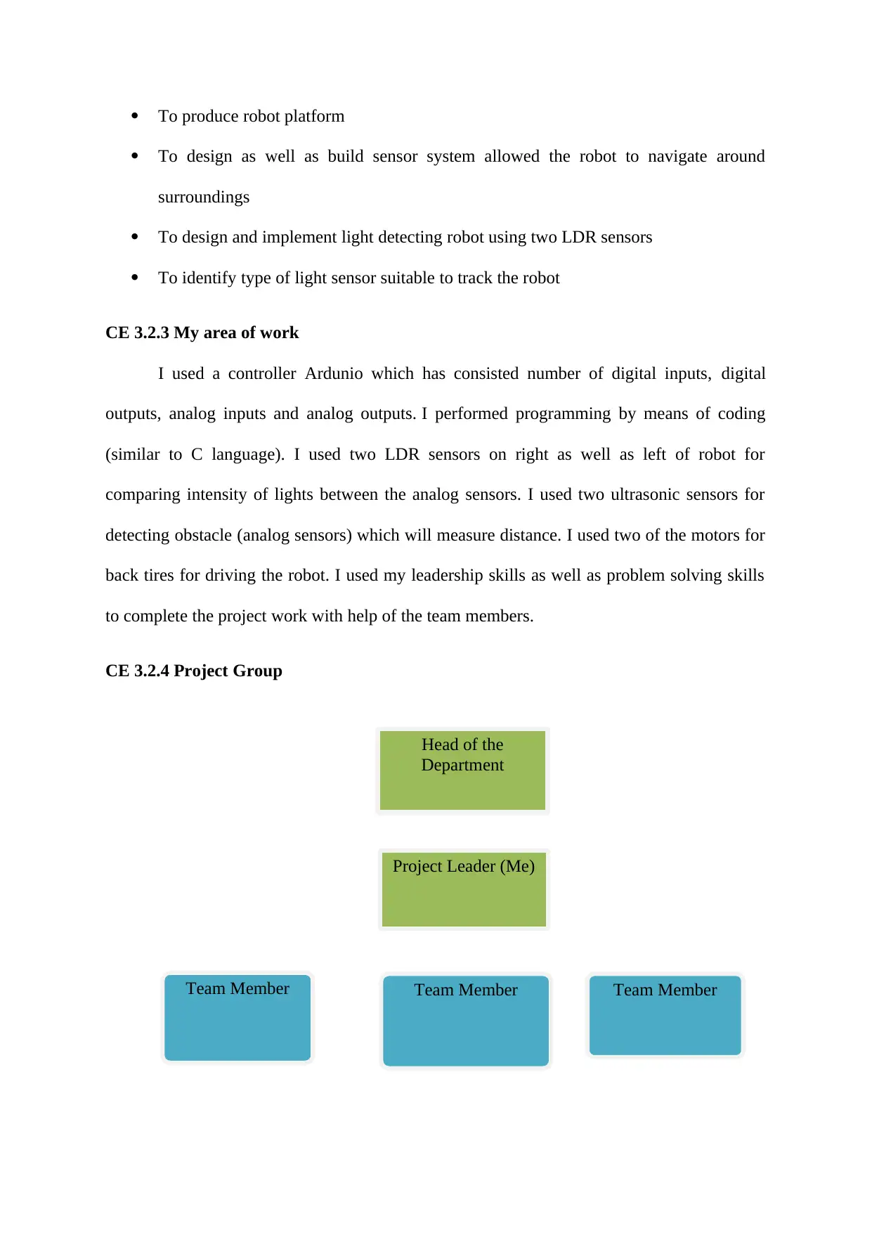
Head of the
Department
Project Leader (Me)
Team MemberTeam Member Team Member
To produce robot platform
To design as well as build sensor system allowed the robot to navigate around
surroundings
To design and implement light detecting robot using two LDR sensors
To identify type of light sensor suitable to track the robot
CE 3.2.3 My area of work
I used a controller Ardunio which has consisted number of digital inputs, digital
outputs, analog inputs and analog outputs. I performed programming by means of coding
(similar to C language). I used two LDR sensors on right as well as left of robot for
comparing intensity of lights between the analog sensors. I used two ultrasonic sensors for
detecting obstacle (analog sensors) which will measure distance. I used two of the motors for
back tires for driving the robot. I used my leadership skills as well as problem solving skills
to complete the project work with help of the team members.
CE 3.2.4 Project Group
⊘ This is a preview!⊘
Do you want full access?
Subscribe today to unlock all pages.

Trusted by 1+ million students worldwide
Figure 1: People involved in the project
CE 3.2.5 My responsibilities throughout the project
Besides the production engineering student as my profession, I comprised variety of
important as well as significant responsibilities. The most key significant responsibility
related to my project was leading my project team members so that I can provide guidance to
make the project work. I proposed a design of the robot so that it is used as maze and sooner
the robot can reach origin of maze to get better robot. I had taken readings of Arduino for
analog sensors are 0 for 0 volts and 1024 for 5 volts and analog outputs as 0 for 0 volts and
255 for 5 volts.
CE 3.3 Distinctive Activity
CE 3.3.1 Comprehending the Theory of Project
For right as well as left of robot, two LDR sensors were used for comparing intensity
of the lights. If the light intensity is more as compared right LDR sensor, then right tire will
stop moving which will lead the robot to turn right. Similarly, if the light intensity is more as
compared left LDR sensor, then left tire will stop moving which will lead the robot to turn
left. I observed that when distance to an obstacle is less than 4 cm by one of ultrasonic
sensors the robot will turn and avoid the obstacle. I analyzed that when distances are both less
than 4 cm the robot will go backwards for 2 seconds and then will depend on the ldr sensor to
detect light.
Paraphrase This Document
Need a fresh take? Get an instant paraphrase of this document with our AI Paraphraser
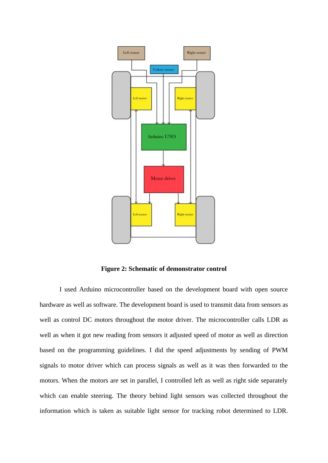
Figure 2: Schematic of demonstrator control
I used Arduino microcontroller based on the development board with open source
hardware as well as software. The development board is used to transmit data from sensors as
well as control DC motors throughout the motor driver. The microcontroller calls LDR as
well as when it got new reading from sensors it adjusted speed of motor as well as direction
based on the programming guidelines. I did the speed adjustments by sending of PWM
signals to motor driver which can process signals as well as it was then forwarded to the
motors. When the motors are set in parallel, I controlled left as well as right side separately
which can enable steering. The theory behind light sensors was collected throughout the
information which is taken as suitable light sensor for tracking robot determined to LDR.
LDR was consisted quicker responses for changes into the light intensity which is required to
track the robot. Main differences among two sensors were as because LDR respond better to
visible light spectrum than photodiode which can respond to better into infra red spectra.
CE 3.3.2 Engineering knowledge and skills applied in the project
I had used my skills of the production engineering to complete the entire project
work. In order to calculate light intensity of LDR sensor, I had considered core knowledge of
the intensities for the colour sensor. I utilized my skills for calculations in addition to
mechanical specifications for assembling the robot with 4 tires to detect lights and moves
towards it. With the team leading skills, I was able to lead entire project team members so
that the work was completed on scheduled time.
CE 3.3.3 Accomplishment and Task Performed
In order to complete the project, I had gained significant project objectives where
there are significant issues which are required to highlight to make accuracy of the sensors
and distances of the robots. While completion of the designing calculations of light detecting
robots, I considered to perform an analysis of readings of Arduino for analog sensors. The
project work was achievable when the robot is being supposed to follow specific light as the
flashlight, but there is ability to let robot drive in normal lit room. For type of detecting robot,
LDR was being selected as proper light sensor. I determined that there is ability to get robot
for avoiding obstacles by means of only colored light were probable with use of the colour
sensor as well as colour was easier to detect was red colour because of longer wavelength.
CE 3.3.4 Identified issues and their solutions
3.3.4.1 Issues
The issues related to light detecting robot are differences into the sensor readings for
LDR sensors as well as ultrasonic sensors where each sensor can calibrate such that it is
⊘ This is a preview!⊘
Do you want full access?
Subscribe today to unlock all pages.

Trusted by 1+ million students worldwide
comparable. In order to add +10 or -20 to one of the sensor in the coding, the comparison
becomes logical. In the project, there is possibility to control the robot by means of only light.
It will reduce investigation of aspects which are required to control detecting robot.
3.3.4.2 Solutions
As a solution to above identified issue, demonstrator is used to steer as per the input
from light sensors and steer towards higher light intensity as well as avoiding obstacles using
input from sensor. The avoidance of obstacle is based on colour coding system by means of
navigation system. When the robot can approach to obstacle, then it performs either left or
right turn dependent on the colour of obstacles.
CE 3.3.5 Plan to produce creative and innovative work
Most important is that the work is be produced an innovative work by working
effectively. I subdivided the entire project work among my project team members and
individual tasks were distributed so that the project work was executed properly. By means of
light sensing to detect robot, two of LDR sensors were used on the right and left of the robot.
The colour sensor was being set at an angle which is not at optimal angle or directions. There
is calculation as well as consideration of best direction as well as angle for putting light
sensors into the cloud to be investigated.
CE 3.4 Project Review
CE 3.4.1 Project Overview
I performed entire project work and ordered various materials required to design the
light detecting robot. The robot testing was performed so that proper results were measured
and calculated. I had utilized production engineering skills as well as knowledge so that I can
stimulate the work successfully. There was proper calculation of all light sensor parameters.
Paraphrase This Document
Need a fresh take? Get an instant paraphrase of this document with our AI Paraphraser

CE 3.4.2 My Contribution to work
I assembled the robot by means of 4 tires to detect lights and moves towards it and
used Ardunio controller for performing the project work. I did programming by means of C
coding. I used two LDR sensors on the right and left of the robot for comparison of intensity
of lights among sensors. I had taken guidance from the project team members so that I can
properly designed the light tracking robot and it was completed on estimated timeframe.
1 out of 8
Related Documents
Your All-in-One AI-Powered Toolkit for Academic Success.
+13062052269
info@desklib.com
Available 24*7 on WhatsApp / Email
![[object Object]](/_next/static/media/star-bottom.7253800d.svg)
Unlock your academic potential
Copyright © 2020–2026 A2Z Services. All Rights Reserved. Developed and managed by ZUCOL.


