University XYZ: Linear Systems and Control Assignment Solution

Verified

Added on  2020/05/11

|9
|525
|147
Homework Assignment
AI Summary
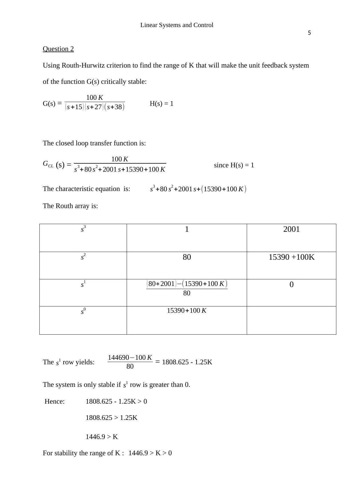
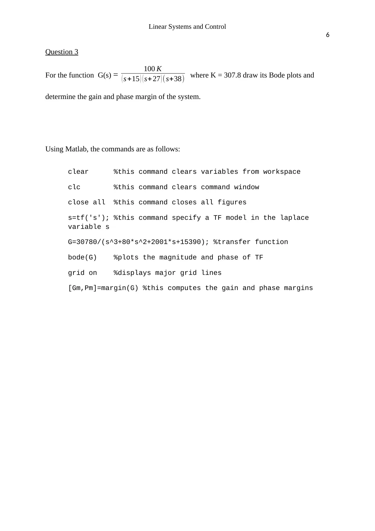
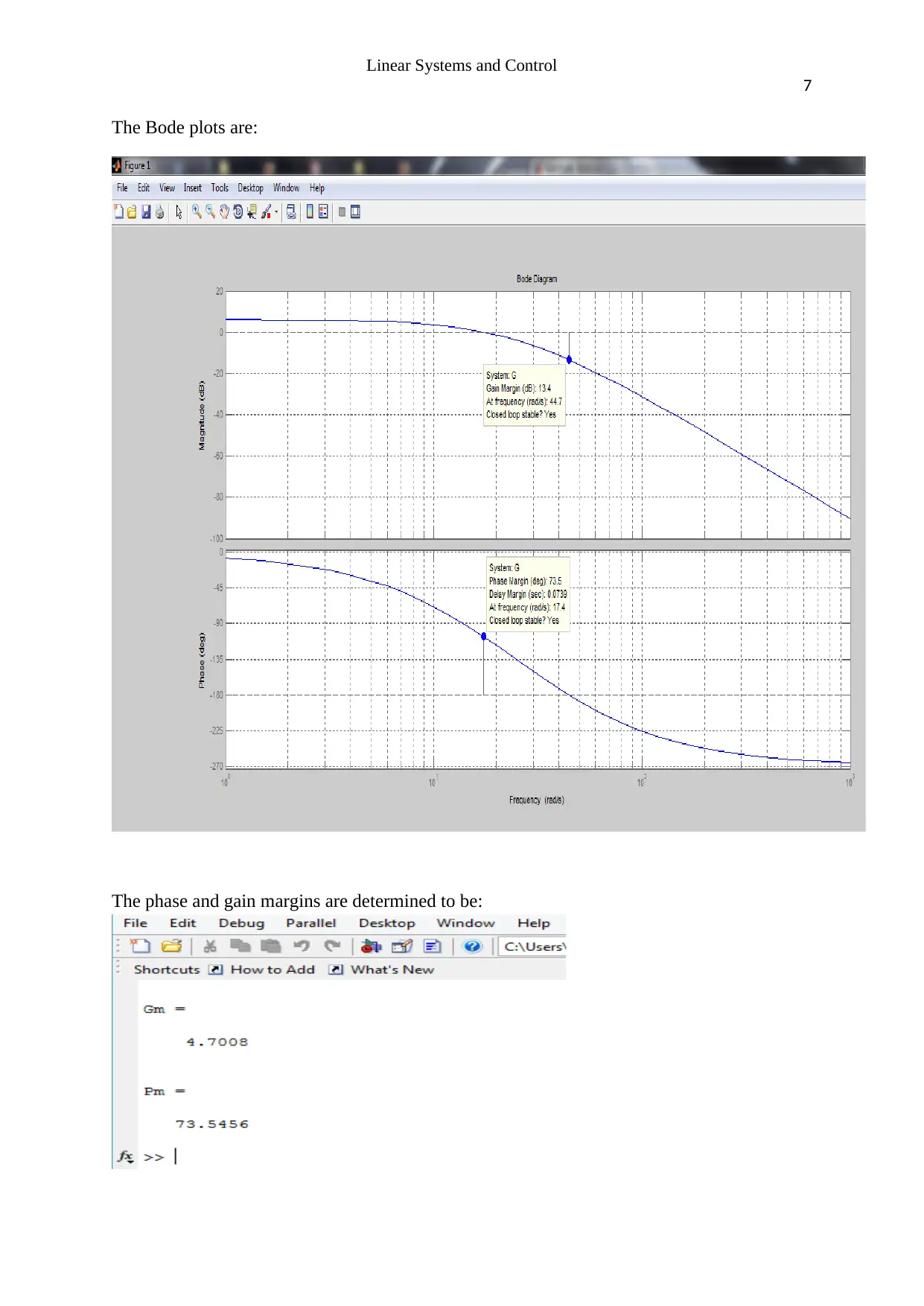
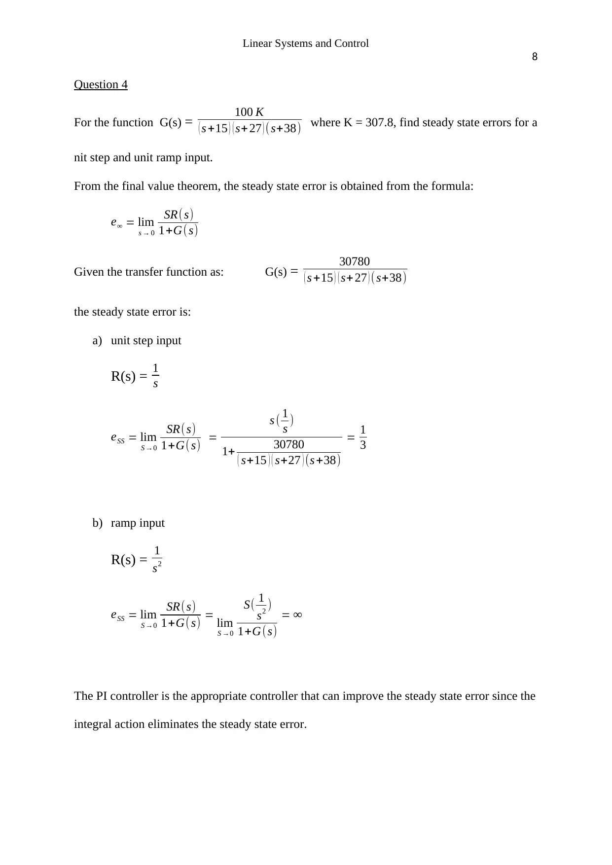
This assignment solution covers key concepts in linear systems and control. It begins by simplifying a block diagram and determining the closed-loop transfer function. The solution then applies the Routh-Hurwitz criterion to find the range of K for a stable unit feedback system. Bode plots are generated using MATLAB for a given transfer function, and the gain and phase margins are determined. Finally, the assignment calculates steady-state errors for unit step and ramp inputs, and suggests the use of a PI controller to improve these errors. The solution references relevant literature, providing a comprehensive understanding of the topics covered. The assignment covers topics such as transfer functions, stability analysis, and controller design, making it a valuable resource for students studying control systems.
Document Page
Running head: Linear Systems and Control
1
Linear systems and control.
Author
Course
Date
tabler-icon-diamond-filled.svg

Secure Best Marks with AI Grader

Need help grading? Try our AI Grader for instant feedback on your assignments.
Document Page
Linear Systems and Control
2
Question 1
Simplify the block diagram and determine the closed-loop transfer function.
a) The block diagram after shifting the summing point of junction 2 to after G1 (s)
becomes:
Document Page
Linear Systems and Control
3
b) Summing the two junctions together as the feedback path is in parallel form reduces
the block to:
c) Blocks G1(s) and G2(s) are connected in positive and negative feedback respectively
and they can be reduced as follows:
Document Page
Linear Systems and Control
4
d) The two blocks are in series and the feedback in parallel and hence can be simplified
to;
Hence now the closed-loop transfer function is:
GCL (s)= C( s)
R( s) = G1 ( s) G2 (s)
(1G1 ( s ) ) (1+G1 ( s ) G2 ( s ) H1 ( s ) +G2 ( s ) ) + (1+H1 ( s ) ) (G1 (s )G2 ( s))
tabler-icon-diamond-filled.svg

Secure Best Marks with AI Grader

Need help grading? Try our AI Grader for instant feedback on your assignments.
Document Page
Linear Systems and Control
5
Question 2
Using Routh-Hurwitz criterion to find the range of K that will make the unit feedback system
of the function G(s) critically stable:
G(s) = 100 K
( s +15 ) ( s+ 27 ) (s+38) H(s) = 1
The closed loop transfer function is:
GCL (s) = 100 K
s3+80 s2+2001 s+15390+100 K since H(s) = 1
The characteristic equation is: s3 +80 s2 +2001 s+(15390+100 K )
The Routh array is:
s3 1 2001
s2 80 15390 +100K
s1 ( 802001 ) (15390+100 K )
80
0
s0 15390+100 K
The s1 row yields: 144690100 K
80 = 1808.625 - 1.25K
The system is only stable if s1 row is greater than 0.
Hence: 1808.625 - 1.25K > 0
1808.625 > 1.25K
1446.9 > K
For stability the range of K : 1446.9 > K > 0
Document Page
Linear Systems and Control
6
Question 3
For the function G(s) = 100 K
( s +15 ) ( s+ 27 ) ( s+38) where K = 307.8 draw its Bode plots and
determine the gain and phase margin of the system.
Using Matlab, the commands are as follows:
clear %this command clears variables from workspace
clc %this command clears command window
close all %this command closes all figures
s=tf('s'); %this command specify a TF model in the laplace
variable s
G=30780/(s^3+80*s^2+2001*s+15390); %transfer function
bode(G) %plots the magnitude and phase of TF
grid on %displays major grid lines
[Gm,Pm]=margin(G) %this computes the gain and phase margins
Document Page
Linear Systems and Control
7
The Bode plots are:
The phase and gain margins are determined to be:
tabler-icon-diamond-filled.svg

Paraphrase This Document

Need a fresh take? Get an instant paraphrase of this document with our AI Paraphraser
Document Page
Linear Systems and Control
8
Question 4
For the function G(s) = 100 K
( s +15 ) ( s+ 27 ) ( s+38) where K = 307.8, find steady state errors for a
nit step and unit ramp input.
From the final value theorem, the steady state error is obtained from the formula:
e = lim
s 0
SR( s)
1+G( s)
Given the transfer function as: G(s) = 30780
( s +15 ) ( s+ 27 ) ( s+38)
the steady state error is:
a) unit step input
R(s) = 1
s
eSS = lim
S 0
SR( s)
1+G( s) =
s ( 1
s )
1+ 30780
( s+15 ) ( s+27 ) (s +38)
= 1
3
b) ramp input
R(s) = 1
s2
eSS = lim
S 0
SR( s)
1+G( s) = lim
S 0
S( 1
s2 )
1+G(s)
=
The PI controller is the appropriate controller that can improve the steady state error since the
integral action eliminates the steady state error.
Document Page
Linear Systems and Control
9
Bibliography
Ogata, K. (2016). Modern control engineering. [Delhi]: Pearson.
Norman, S. (2011). Control systems engineering. [California]: John Wiley & Sons
chevron_up_icon
1 out of 9
circle_padding
hide_on_mobile
zoom_out_icon
logo.png

Your All-in-One AI-Powered Toolkit for Academic Success.

Available 24*7 on WhatsApp / Email

[object Object]