Liquid Level Control System: Design and Operational Analysis
VerifiedAdded on 2023/06/08
|10
|2686
|419
Report
AI Summary
This report presents the design of a liquid level control system, crucial for various applications, including industrial settings. It begins with a needs definition, highlighting the importance of preventing liquid overflow and the associated losses. The conceptual design explores open and closed-loop control systems, emphasizing the use of feedback mechanisms. Key components such as Arduino, ultrasonic modules, programmable logic controllers (PLCs), water tanks, and electric pumps are discussed. The evaluation section details the hardware and software components, including programming languages and microcontrollers. The report further elaborates on the operational aspects of the system, including sensor integration, signal processing, and the control of the electric pump based on liquid level readings. The design utilizes sensors to detect liquid levels and trigger the pump accordingly, ensuring efficient and safe liquid management. The report also references various sources to support the design and implementation of the liquid level control system.
Liquid Level Control System 1
DESIGNING A LIQUID LEVEL CONTROLLER SYSTEM
A Design Paper on Design System By
Student’s Name
Name of the Professor
Institutional Affiliation
City/State
Year/Month/Day
DESIGNING A LIQUID LEVEL CONTROLLER SYSTEM
A Design Paper on Design System By
Student’s Name
Name of the Professor
Institutional Affiliation
City/State
Year/Month/Day
Paraphrase This Document
Need a fresh take? Get an instant paraphrase of this document with our AI Paraphraser
Liquid Level Control System 2
Table of Contents
INTRODUCTION...........................................................................................................................................3
NEEDS DEFINITION......................................................................................................................................3
CONCEPTUAL DESIGN..................................................................................................................................5
EVALUATION................................................................................................................................................6
Operation of Liquid Level Controller System...........................................................................................9
BIBLIOGRAPHY...........................................................................................................................................10
Liquid Level Control System 3
INTRODUCTION
Water tanks form major source of water in industries, farms, or hotels especially in case
where the piped water is not sufficient or reliable. The water tanks provides a backup source of
water in these places and the water is normally pumped in these water tanks by these of electric
pump. When the tank is almost used, then the electric pump is switched on and the water is
pumped to the tank, while when the water in the tank is almost full, then the electric pump is
switched off by physically observing the level of water in the tank. This research paper seeks to
design a liquid level control system which has the ability to regulate the level of water or any
other liquid in the tank through the incorporation of a mechanism of feedback control.
In this system of feedback control, there is the comparison of the results of output before
a suitable corrective mechanism is taken. In this feedback control system, there is usually a
command issued to the system with an assumption that the mechanism will function properly.
Any system of control can be classified as sequential, continuous, or discrete control systems. A
liquid level control system is very important since it helps in the prevention of losses that occur
due to overfilling of the liquid tank depending on the liquid that is being pumped by the electric
pump to the tank. There are cases where the type of liquid being pumped into the tank is of high
value and this means that the company will incur high losses in case of overflow (Bakshi, 2010).
NEEDS DEFINITION
This design of a liquid level controller system is a very significant control system that
will be used in controlling the pumping of any type of liquid in a tank situated above the ground.
Controlling the pumping of liquid by an electric pump will prevent wastage caused by overfilling
of the tank during the process of pumping. The most common way of checking if the liquid being
pumped into the tank is almost full is through physically and constantly checking the level of
⊘ This is a preview!⊘
Do you want full access?
Subscribe today to unlock all pages.
Trusted by 1+ million students worldwide
Liquid Level Control System 4
liquid in the tank. This normally results in a lot of time wastage since the individual must
constantly be visiting the tank to check the level of water in the tank so as to be ready to turn the
electric pump off in case the liquid is almost filling the tank (Chau, 2012).
There are also cases where the liquid being pumped into the tank may have some health
effect when inhaled by an individual. The observer will be required to constantly check the level
of liquid that has been the pump in the tank and also not the duration it will take before the tank
is filled. Opening the tank for the purpose of observation can be dangerous to the people working
around the tank. The liquid level controller system will ensure that no person will get into
contact with the liquid being pumped since this control system can automatically regulate the
level of liquid being pumped in the tank by an electric pump through the incorporation of a
feedback control (Cho, 2010).
The liquid level controller system is an important control system in the prevention of
losses that may occur as a result of overfilling of the liquid in the tank depending on the type of
liquid that is being pumped into the tank by the electric pump. Overfilling of the tank resulting in
the liquid overflowing from the tank can also be dangerous if the liquid is flammable or harmful
to human health since their spillage may pose a serious danger to the employees working of the
company and also to the company as a whole. The dangers, time wastage, and health effects
caused by overfilling of any liquid being pumped to the pump by an electric pump is the major
reason why the design of a liquid level controller system is significant for both households and
commercial purposes. This research paper seeks to come up with a conceptual design of a liquid
level controller system which can be used for both small-scale and also for commercial purposes
(Dorf, 2009).
Paraphrase This Document
Need a fresh take? Get an instant paraphrase of this document with our AI Paraphraser
Liquid Level Control System 5
CONCEPTUAL DESIGN
Any control system can either be an open loop or a closed loop control system. In the
control loop system, there is a comparison of the results or output of the system before an
appropriate corrective action is taken to rectify the situation. In the open loop control systems, a
command is issued to the control system with an assumption that the system will function
properly. A control system can be classified into the sequential, continuous, and discrete control
system. A sequential control system may cause a machine or system to go through a functionality
series like the elimination of milking machine from a can after there is no more milk left in the
parlour, and then open the gate to allow the cow walk out (Gopal, 2009).
This paper focuses on the design and implementation of a simple and effective proposal
of a feedback regulator that can be used in water level sensing and control. The two traditional
methods of finding out the level of liquid in a tank enclosed can be though tapping the sides of
the tank until sudden changes in the sound produced during tapping are noted or through
removing the lead of the tank and then inserting a measuring stick to determine the level of
liquid in the tank. There is a need of designing a more advanced method of sensing the liquid
level in the tank by the application of electrical circuit established for such applications. Variety
of circuits can be established and deployed for water sensing based on integrated circuit
technology and the signal output from the sensor of water (Ibrahim, 2013).
Many modern processes in industrial, commercial, and medical applications do not
require advance temperature ranges despite the pressure sensor being sensitive to temperature.
The design illustrates a cost-effective, low-power, liquid-level control, and delivery system based
on the system of data acquisition which utilizes a compensated silicon pressure sensor and high-
precision delta-sigma. In the automated control system design, a closed-loop system is used
Liquid Level Control System 6
which applies the liquid level in the tank as the input to control the power supply to the electric
pump. Therefore, the output is expected to be a discrete variable actuated by the application of an
electrical circuitry (Langari, 2012).
The liquid level is expected to be scrutinized by the application of two electronic sensors
situated at an appropriate location to detect low and high values of liquid levels. The output
signal is expected to be fed into the circuit where it is transduced into an ON or OFF signal
which regulates the power supply to the pump. The major advantaged of this proposed design is
that it is not restricted to the size and nature of the tank with liquid. Therefore, any tank with
liquid can be converted into a control tank by coupling the circuit and including the regulator
sensor inside the tank (Mohd, 2011).
EVALUATION
This section evaluates the hardware components and the software components required
during the design of a liquid level controller system. The software components that can be used
in the design of a liquid level controller system include MC Programming language and Arduino
compiler. The hardware components that can be used in designing a liquid level controller
system include relay, lamp, diodes, ultrasonic module, transformer, crystal display, holder, LED,
voltage regulator, transistor, MOSFET, and the microcontroller unit. Arduino compiler is a board
with many microprocessors and controllers and also sets of digital and analogue output and input
pins that may be coupled with many expansion boards and circuits (Mutambara, 2011).
The PC is used in monitoring and modification of the feedback signal from the sensor
of pressure and transmits a control signal for the selection of three diverse modes of operation
and allow the input liquid level set point, sample time, and values of Arduino compiler. The
ultrasonic module is applied during turning ON or OFF the motor or pump when there is a drop
⊘ This is a preview!⊘
Do you want full access?
Subscribe today to unlock all pages.
Trusted by 1+ million students worldwide
Liquid Level Control System 7
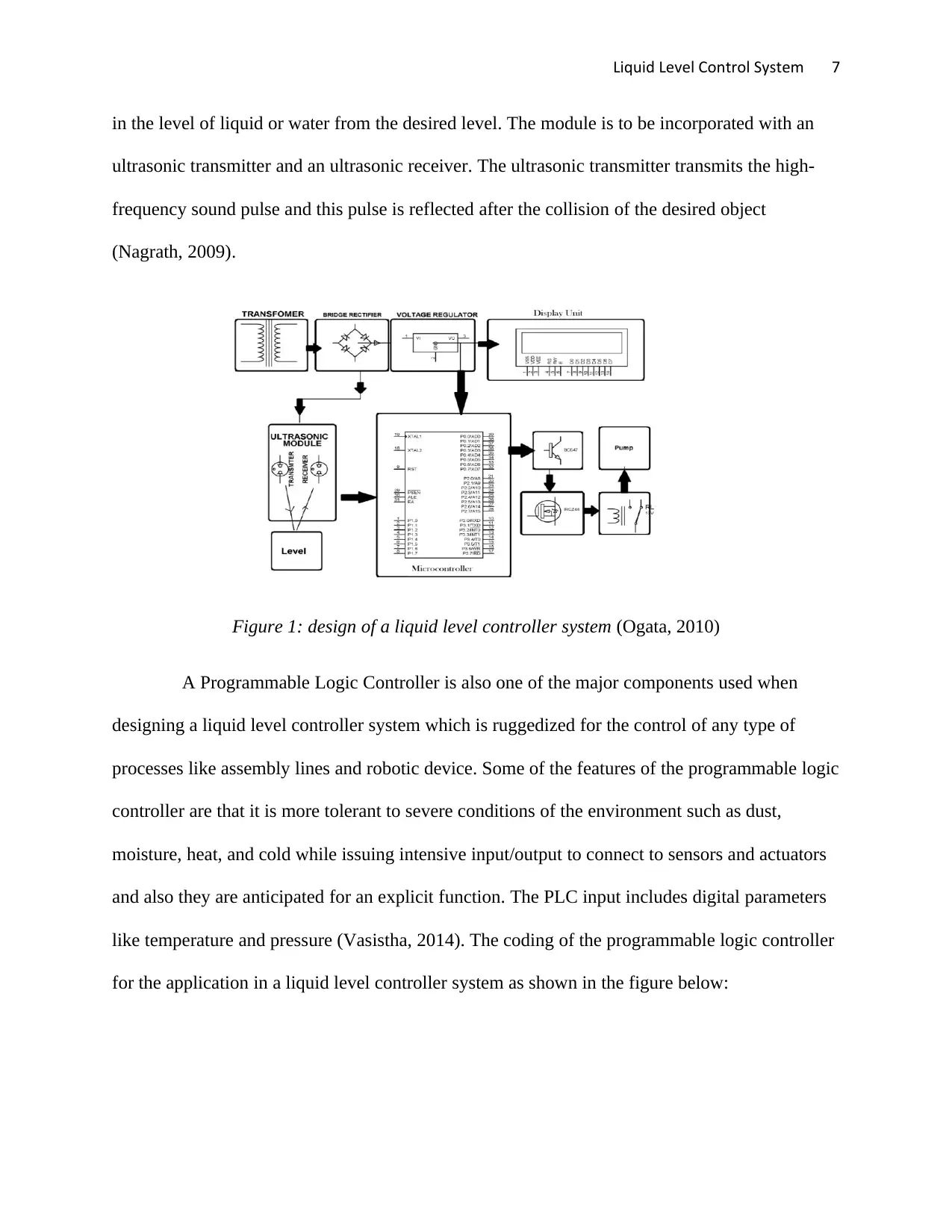
in the level of liquid or water from the desired level. The module is to be incorporated with an
ultrasonic transmitter and an ultrasonic receiver. The ultrasonic transmitter transmits the high-
frequency sound pulse and this pulse is reflected after the collision of the desired object
(Nagrath, 2009).
Figure 1: design of a liquid level controller system (Ogata, 2010)
A Programmable Logic Controller is also one of the major components used when
designing a liquid level controller system which is ruggedized for the control of any type of
processes like assembly lines and robotic device. Some of the features of the programmable logic
controller are that it is more tolerant to severe conditions of the environment such as dust,
moisture, heat, and cold while issuing intensive input/output to connect to sensors and actuators
and also they are anticipated for an explicit function. The PLC input includes digital parameters
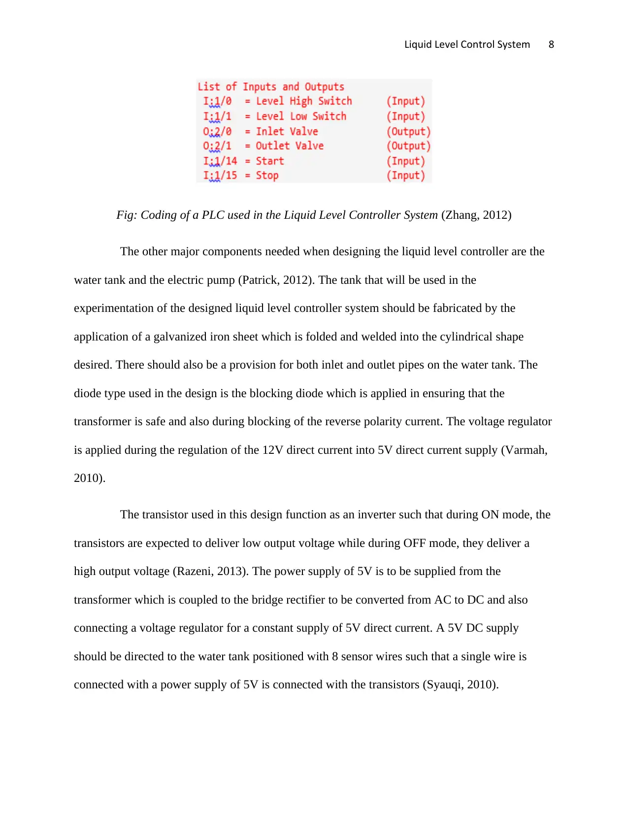
like temperature and pressure (Vasistha, 2014). The coding of the programmable logic controller
for the application in a liquid level controller system as shown in the figure below:
in the level of liquid or water from the desired level. The module is to be incorporated with an
ultrasonic transmitter and an ultrasonic receiver. The ultrasonic transmitter transmits the high-
frequency sound pulse and this pulse is reflected after the collision of the desired object
(Nagrath, 2009).
Figure 1: design of a liquid level controller system (Ogata, 2010)
A Programmable Logic Controller is also one of the major components used when
designing a liquid level controller system which is ruggedized for the control of any type of
processes like assembly lines and robotic device. Some of the features of the programmable logic
controller are that it is more tolerant to severe conditions of the environment such as dust,
moisture, heat, and cold while issuing intensive input/output to connect to sensors and actuators
and also they are anticipated for an explicit function. The PLC input includes digital parameters
like temperature and pressure (Vasistha, 2014). The coding of the programmable logic controller
for the application in a liquid level controller system as shown in the figure below:
Paraphrase This Document
Need a fresh take? Get an instant paraphrase of this document with our AI Paraphraser
Liquid Level Control System 8
Fig: Coding of a PLC used in the Liquid Level Controller System (Zhang, 2012)
The other major components needed when designing the liquid level controller are the
water tank and the electric pump (Patrick, 2012). The tank that will be used in the
experimentation of the designed liquid level controller system should be fabricated by the
application of a galvanized iron sheet which is folded and welded into the cylindrical shape
desired. There should also be a provision for both inlet and outlet pipes on the water tank. The
diode type used in the design is the blocking diode which is applied in ensuring that the
transformer is safe and also during blocking of the reverse polarity current. The voltage regulator
is applied during the regulation of the 12V direct current into 5V direct current supply (Varmah,
2010).
The transistor used in this design function as an inverter such that during ON mode, the
transistors are expected to deliver low output voltage while during OFF mode, they deliver a
high output voltage (Razeni, 2013). The power supply of 5V is to be supplied from the
transformer which is coupled to the bridge rectifier to be converted from AC to DC and also
connecting a voltage regulator for a constant supply of 5V direct current. A 5V DC supply
should be directed to the water tank positioned with 8 sensor wires such that a single wire is
connected with a power supply of 5V is connected with the transistors (Syauqi, 2010).
Liquid Level Control System 9
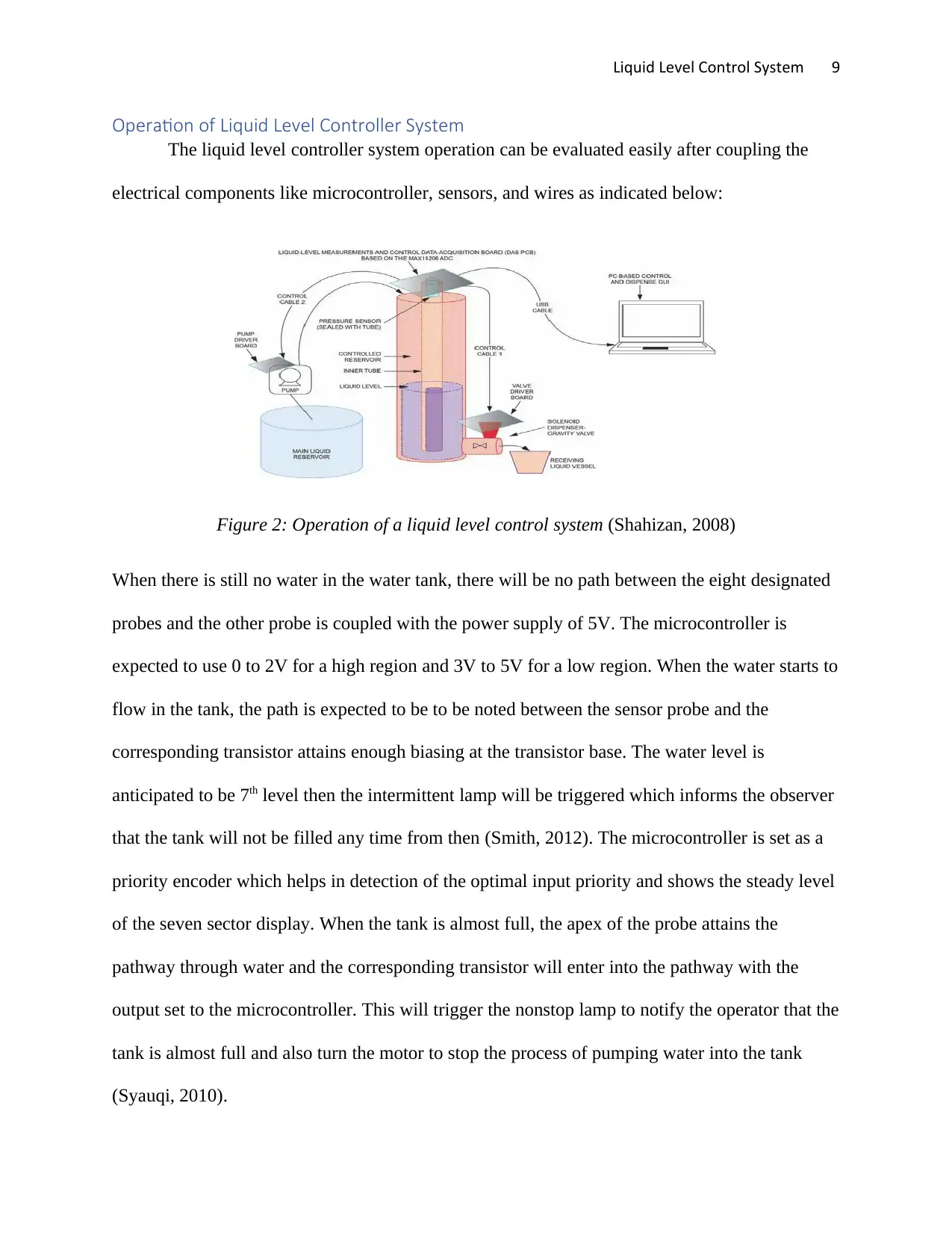
Operation of Liquid Level Controller System
The liquid level controller system operation can be evaluated easily after coupling the
electrical components like microcontroller, sensors, and wires as indicated below:
Figure 2: Operation of a liquid level control system (Shahizan, 2008)
When there is still no water in the water tank, there will be no path between the eight designated
probes and the other probe is coupled with the power supply of 5V. The microcontroller is
expected to use 0 to 2V for a high region and 3V to 5V for a low region. When the water starts to
flow in the tank, the path is expected to be to be noted between the sensor probe and the
corresponding transistor attains enough biasing at the transistor base. The water level is
anticipated to be 7th level then the intermittent lamp will be triggered which informs the observer
that the tank will not be filled any time from then (Smith, 2012). The microcontroller is set as a
priority encoder which helps in detection of the optimal input priority and shows the steady level
of the seven sector display. When the tank is almost full, the apex of the probe attains the
pathway through water and the corresponding transistor will enter into the pathway with the
output set to the microcontroller. This will trigger the nonstop lamp to notify the operator that the
tank is almost full and also turn the motor to stop the process of pumping water into the tank
(Syauqi, 2010).
⊘ This is a preview!⊘
Do you want full access?
Subscribe today to unlock all pages.
Trusted by 1+ million students worldwide
Liquid Level Control System 10
BIBLIOGRAPHY
Bakshi, U., 2010. Principles Of Control Systems. New York: Technical Publications.
Chau, P., 2012. Process Control: A First Course with MATLAB. London: Cambridge University Press.
Cho, C., 2010. Measurement and Control of Liquid Level. 2009: Instrument Society of America.
Dorf, R., 2009. Modern Control Systems. Colorado: Upper Saddle River,.
Gopal, M., 2009. Control Systems (As Per Latest Jntu Syllabus). Berlin: New Age International.
Ibrahim, D., 2013. Microcontroller Based Applied Digital Control. Toledo: Wiley,2013.
Langari, R., 2012. Measurement and Instrumentation: Theory and Application. Paris: Academic Press.
Mohd, S., 2011. Fuzzy Logic Controller Simulation for Water Tank Level Control. London: KUKTEM.
Mutambara, A., 2011. Design and Analysis of Control Systems. Michigan: CRC Press.
Nagrath, J., 2009. Control Systems Engineering. Moscow: New Age International.
Ogata, K., 2010. Modern Control Engineering, 4th ed. Colorado: Upper Saddle River.
Patrick, D., 2012. Industrial Process Control Systems. Perth: The Fairmont Press, Inc.
Razeni, S., 2013. Liquid Level Control of a Couple Tank System Based on Smooth Trajectory Tracking
Using PID Controller. New York: UMP.
Shahizan, M., 2008. Implementation of LQR Controller on Coupled Tank Liquid Level System. Toledo:
UMP.
Smith, M., 2012. Continuous System Simulation. Perth: Springer Science & Business Media.
Syauqi, A., 2010. Level Control (tank 1) of Coupled Tank Liquid Level System Using Integral Control State
Feedback Controller. New York: UMP.
Varmah, K., 2010. Control Systems. Colorado: Tata McGraw-Hill Education.
Vasistha, V., 2014. PID output fuzzified water level control in MIMO coupled tank system. Michigan: GRIN
Publishing.
Zhang, W., 2012. Software Engineering and Knowledge Engineering. Melbourne: Springer Science &
Business Media.
1 out of 10
Related Documents


Your All-in-One AI-Powered Toolkit for Academic Success.
+13062052269
info@desklib.com
Available 24*7 on WhatsApp / Email
![[object Object]](/_next/static/media/star-bottom.7253800d.svg)
Unlock your academic potential
Copyright © 2020–2026 A2Z Services. All Rights Reserved. Developed and managed by ZUCOL.