REET 420 - Power Electronics: LM2595 Buck Converter Lab Report

Verified

Added on  2023/01/11

|5
|931
|58
Report
AI Summary
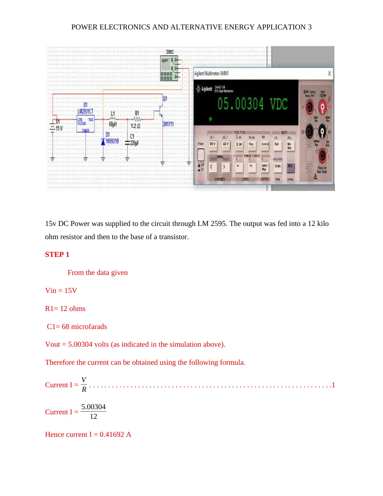
This lab report details the design, construction, and analysis of a buck converter using the LM2595 regulator. The report begins with an introduction to buck converters, also known as step-down regulators, and their key components, including the transistor switch, free-wheel diode, and output inductor and capacitor. The objective is to design a buck converter, and the report provides a circuit diagram, component list, and calculations for important parameters like current, power, and junction temperature. The report then addresses questions about the operation of the LM2595, which functions as a voltage regulator, and the concept of ripple current, explaining how to minimize it. The report also includes observations, measurements, and simulation results, providing a comprehensive overview of the design and implementation of the buck converter, as well as the design methodology.
Document Page
POWER ELECTRONICS AND ALTERNATIVE ENERGY APPLICATION 1
POWER ELECTRONICS AND ALTERNATIVE ENERGY APPLICATION
By Name
Course
Instructor
Institution
Location
Date
tabler-icon-diamond-filled.svg

Secure Best Marks with AI Grader

Need help grading? Try our AI Grader for instant feedback on your assignments.
Document Page
POWER ELECTRONICS AND ALTERNATIVE ENERGY APPLICATION 2
Title: THE BUCK CONVERTER
Objective: DESIGN A BUCK CONVERTER USING AN LM2595
INTRODUCTION
The buck regulator is the basic circuit required to convert a high-voltage, dc input to a
lower voltage, dc output. Also known as a step-down regulator, the buck consists of several key
power components, including the transistor switch, the free-wheel diode, and the output inductor
and capacitor. When a buck converter is driven from an AC line in, it is known as an AC/DC
buck converter and is typically preceded in the circuit by a full-wave rectifier that converts the ac
to an unregulated dc that is input into the buck. It is crucial to be able to select the major
components of the discrete buck in order to deliver the specified, regulated output voltage
reliably. The voltage regulation is typically handled by an IC controller, such as the LM2595,
which must be properly applied by the designer. Before beginning your Lab, download your Lab
cover page here (Links to an external site.)Links to an external site.
Components for the experiment
DC Power Supply
LM 2595 Regulator
Zener diode (1N5921B)
Capacitor 220micro farads
Resistor 12 ohms
Multimeter.
Set-up and Procedure.
The circuit diagram for the experiment was set as below;
Document Page
POWER ELECTRONICS AND ALTERNATIVE ENERGY APPLICATION 3
15v DC Power was supplied to the circuit through LM 2595. The output was fed into a 12 kilo
ohm resistor and then to the base of a transistor.
STEP 1
From the data given
Vin = 15V
R1= 12 ohms
C1= 68 microfarads
Vout = 5.00304 volts (as indicated in the simulation above).
Therefore the current can be obtained using the following formula.
Current I = V
R . . . . . . . . . . . . . . . . . . . . . . . . . . . . . . . . . . . . . . . . . . . . . . . . . . . . . . . . . . . . . . . . .1
Current I = 5.00304
12
Hence current I = 0.41692 A
Document Page
POWER ELECTRONICS AND ALTERNATIVE ENERGY APPLICATION 4
And the Power Supplied to IC can be obtained using the below formula,
Power Supplied to IC= V×I . . . . . . . . . . . . . . . . . . . . . . . . . . . . . . . . . . . . . . . . . . . . . . . . . . . . . . 2
Power Supplied to IC = V×I
Power Supplied to IC = 15×0.41692
Power Supplied to IC = 6.2538 watts
While the power dissipated, P is given by the following equation;
Power dissipated, P= I2R . . . . . . . . . . . . . . . . . . . . . . . . . . . . . . . . . . . . . . . . . . . . . . . . . . . . . . . . 3
Power dissipated, P= 0.416922×12
Power dissipated = 2.0856 watts
And the junction temperature is obtained using the following equation
Jt = Ta +( Ra×Pd) . . . . . . . . . . . . . . . . . . . . . . . . . . . . . . . . . . . . . . . . . . . . . . . . . . . . . . . . . . . . .4
Where Jt is the junction temperature, Ta is the ambient temperature and Pd is the power
dissipated by IC.
Hence Jt = 50 + (12× 2.0856)
Junction temperature = 50+ 34.272
Junction temperature = 84.2720C
The duty cycle from the above
STEP 2. QUESTIONS AND DISCUSSION.
Question 1. Operation of LM2595.
The chip LM2595 is grouped as a Regulator (Voltage regulator). It has an integrated circuit
which offers an important function for instant step-down (buck). The regulator is able to drive a
load rated 1 A. The chip incorporates an internal fixed frequency oscillator and it functions at a
switching frequency of about 150 KHz. When a given voltage is fed into the regulator, the signal
tabler-icon-diamond-filled.svg

Secure Best Marks with AI Grader

Need help grading? Try our AI Grader for instant feedback on your assignments.
Document Page
POWER ELECTRONICS AND ALTERNATIVE ENERGY APPLICATION 5
is converted again into DC form but with less magnitude. This process is made effective by
internal fixed frequency oscillator.
Question 2. Ripple current.
Basically, ripple current is an electrical signal which arises because of incomplete attenuation of
the AC sinusoidal signal in a particular power supply. Ripple current increases with an increase
in the frequency of oscillation. Ripple current factor is always expressed as a percentage. It is
defined by the ratio of RMS (root mean Square) value of the ripple current to the absolute value
based on the condition of the output DC voltage. The magnitude of ripple current depends on the
load resistor value and the size of the capacitor. The current can hence be reduced by increasing
the value of C (Capacitance). Mathematically the ripple
chevron_up_icon
1 out of 5
circle_padding
hide_on_mobile
zoom_out_icon
[object Object]