University Project: Mechanical Engineering LMI System Report Analysis
VerifiedAdded on 2022/09/12
|8
|1893
|10
Report
AI Summary
This report presents a comprehensive analysis of a Load Moment Indicator (LMI) system, crucial for enhancing crane safety and operational efficiency. The introduction highlights the importance of LMI systems in preventing accidents by monitoring load and arm moments. The design section details the system's components, including input sensors (pressure and angle sensors), a control unit, and output devices, with Labview software used for simulation. The software program's functionality is explained, and the results and analysis section covers sensor types and calculations for crane lifting capacity. Furthermore, the report evaluates signal conditioning elements and proposes future developments, such as low-cost controllers and wireless data transmission methods, including the potential of IoT and Virtual Reality. The report concludes with references supporting the analysis.

Mechanical Engg.
MP4706
LOAD MOMENT INDICATOR (LMI) SYSTEM
Name –
ID -
MP4706
LOAD MOMENT INDICATOR (LMI) SYSTEM
Name –
ID -
Paraphrase This Document
Need a fresh take? Get an instant paraphrase of this document with our AI Paraphraser

Contents
INTRODUCTION.....................................................................................................................................3
DESIGN OF LMI SYSTEM......................................................................................................................4
SOFTWARE PROGRAM FOR LMI SYSTEM...............................................................................................5
RESULTS AND ANALYSIS.........................................................................................................................5
SIGNAL CONDITIONING ELEMENTS EVALUATION.................................................................................6
PROPOSAL FOR FUTURE DEVELOPMENT...............................................................................................7
Low Cost Controller...........................................................................................................................7
Data transmission Methods...............................................................................................................7
References :...........................................................................................................................................8

INTRODUCTION
The measurement of the arm’s moment value and the bearing force is carried out by the Load
Moment Indicator ( LMI ) system. If the load being lifted is above the threshold value, the
crane’s arm may not be capable of lifting it and the mechanical structure may be affected. A
failure may occur in such a case. The operator must be given proper and timely signal if the
crane’s load capacity is increased. The 2 types of sensors which can be used are : Pressure
sensor and angle sensor. The system can help to increase the safety of the crane system. In
case of an overload , an LED can be blinked to denote the overload condition.
The work done by a crane can impose a danger at any time during its operation. A dynamic
system must be employed to ensure the safety of the operation being carried out. The
threshold limits can be set for various parameters and then if these threshold values are
crossed, then the operator must be informed about the same so that timely action by the
operator can prevent any type of mishappening.
A load moment indicator ( LMI ) system is a type of controller which can be employed in the
monitor as well as control of the various operations that a crane performs. The various inputs
and output values have been considered here. The crane helps to move an object and lift it
from one position to the other. The operator performing these operations must be able to see
the real time values of various parameters on an LCD display screen in his cabin. This
prevents any accident and makes the system safe. The various parameters are – the carrying
capacity of the lift, output at boom etc.
⊘ This is a preview!⊘
Do you want full access?
Subscribe today to unlock all pages.

Trusted by 1+ million students worldwide
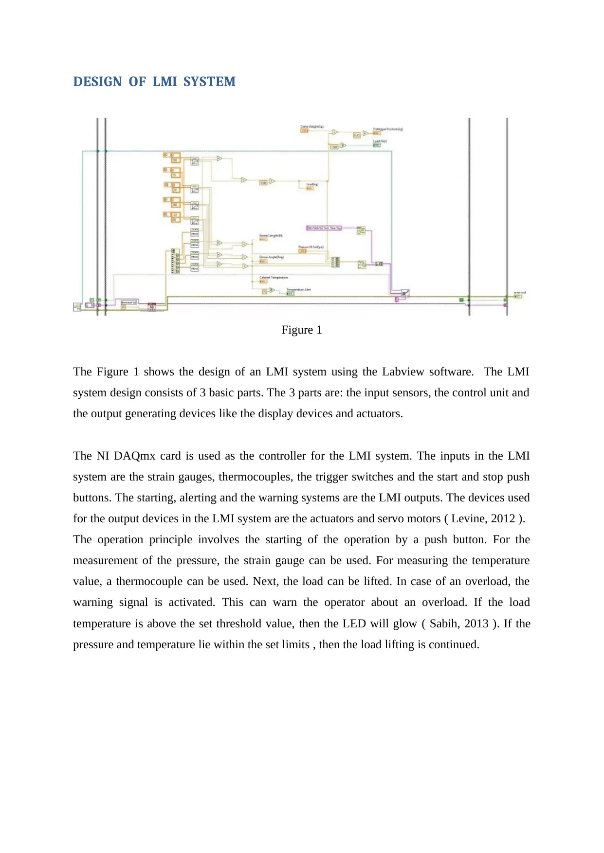
DESIGN OF LMI SYSTEM
Figure 1
The Figure 1 shows the design of an LMI system using the Labview software. The LMI
system design consists of 3 basic parts. The 3 parts are: the input sensors, the control unit and
the output generating devices like the display devices and actuators.
The NI DAQmx card is used as the controller for the LMI system. The inputs in the LMI
system are the strain gauges, thermocouples, the trigger switches and the start and stop push
buttons. The starting, alerting and the warning systems are the LMI outputs. The devices used
for the output devices in the LMI system are the actuators and servo motors ( Levine, 2012 ).
The operation principle involves the starting of the operation by a push button. For the
measurement of the pressure, the strain gauge can be used. For measuring the temperature
value, a thermocouple can be used. Next, the load can be lifted. In case of an overload, the
warning signal is activated. This can warn the operator about an overload. If the load
temperature is above the set threshold value, then the LED will glow ( Sabih, 2013 ). If the
pressure and temperature lie within the set limits , then the load lifting is continued.
Paraphrase This Document
Need a fresh take? Get an instant paraphrase of this document with our AI Paraphraser

SOFTWARE PROGRAM FOR LMI SYSTEM
The measurement explorer must be opened in the Labview software and the required devices
and interfacing elements must be selected. The temperature can be measured using the
DAQmx card by NI which uses a virtual type of channel. The outrigger represents the counter
weight which can be balanced by the crane to make it stable ( Lijuan, 2012 ).
The Figure 2 shows the front panel of the design made here. It represents the Load Moment
Indicator. It has entries for the crane weight ( in kg ), pressure of soil ( in psi ), load value ( in
kg ), the boom length ( in m ), the outrigger position ( in kg ) and the boom angle ( in
degree ). The cabinet temperature has also been represented. The alert buttons for
temperature as well as load have been provided. The start , stop and exit buttons help to
control the system.
Figure 2
RESULTS AND ANALYSIS
The types of sensors used for the analysis are: the pressure transducer and the temperature
sensor. The connection of the pressure transducer is done with NI DAQ.
The lifting capacity of the crane can be calculated using certain parameters. It can be given
by : r * h * C * 0.01. Here, ‘r’ is the range ( distance between the base and heap ) and h * C is
the limit of lift stature time. The design has specific limits which are dependent on the

distance from which the object is picked. A table can be designed which can store these
values.
The other dimensions of the crane depending on its geometry can also be determined which are of
significance. The Pythagoras theorem can be applied to the right triangle formed in the structure of
the crane system. The arm of the blast can be considered to be the hypotenuse, ‘r’ represents the
separation of the outrigger base with heap and the height is the vertical distance of the tip of the
blast.
SIGNAL CONDITIONING ELEMENTS EVALUATION
The strain gauge is made up of a metal. It consists of metal or steel foil which has an
arrangement as a grid. The use of the design of a grid helps to maximize the steel quantity.
The cross section is minimised which helps to control the pressure value and the value of the
Poisson strain. The specimen which needs to be tested is attached to the grid by the help of a
thin film. The specimen experiences some pressure which is then transferred to the stress
gauge which can measure the value of this pressure using an electrical component like the
resistance. The range can be from 30 W to 3 kW ( Precup, 2016 ).
The capacity of lifting can be easily computed. Perhaps the most undertaking in human
business is to neutralize the power of gravity, and to lift structures such as extensions and
structures adequate to look up to the gravity which of the individuals they convey is placed
upon their mass. Someone must have a method to actually assemble these devices, and one of
the leading noticeable bits of equipment to lift enormous objects in exact ways is the crane.
The operation of the crane is carried out from a moving and pivoted part which is referred to
as the outrigger base. Its width is of few metres. For the lifting action, the arm of the blast can
expand in the top and front directions for an edge value given. The length of the arm of blast
and height need to be considered for raising and moving a heap.
A crane is said to be in equilibrium state, when the balance plane has no part which is in the
moving state. Hence, the sum of the external power is zero. Also, the sum of the external
torques is zero. The H – pillar consists of 3 parts. The tension force is the best one out of the
3.
⊘ This is a preview!⊘
Do you want full access?
Subscribe today to unlock all pages.

Trusted by 1+ million students worldwide
PROPOSAL FOR FUTURE DEVELOPMENT
Low Cost Controller
The cost of the system can be reduced by using a controller which has a low cost. If the
sensors having a low cost are used, then this may affect the quality of measurement because
low quality sensors may not be effective in the accurate measurement of the parameters.
Today, many microcontrollers are available which have a low cost like Arduino, Raspberry
Pi. They provide open source platforms for the implementation of the design. They provide
very simple programming techniques and very good interfacing facilities for the sensors
which makes them effective in design of systems. The LMI system can be easily designed
using any of these microcontrollers which will cost lesser ( Aslam, 2020 ).
Data transmission Methods
The data can be transmitted using the wired connection or by a wireless system. The wired
system is complex and difficult in handling. The wireless system is very easy to use and
simpler to operate. In the future designs, the wireless method of transmission must be
preferred. An upcoming technology is the IoT ( Internet of Things ). IoT helps to connect the
various parts of a system by the help of internet. This helps in generating the complete
behaviour of the system so that proper and timely decisions can be made. Another concept
which can be used is the Virtual Reality ( Oğraş, 2013 ).
Paraphrase This Document
Need a fresh take? Get an instant paraphrase of this document with our AI Paraphraser

References :
Aslam, M.S., Dai, X., Hou, J., Li, Q., Ullah, R., Ni, Z. and Liu, Y., 2020. Reliable control
design for composite‐driven scheme based on delay networked T‐S fuzzy
system. International Journal of Robust and Nonlinear Control, 30(4), pp.1622-1642.
Lijuan, X.X.L.H.X. and Lianhui, Y., 2012. High precision periodic control method of control
moment gyro gimbal system. Journal of Beijing University of Aeronautics and Astronautics,
(8), p.8.
Levine, S.E., Bida, T.A., Chylek, T., Collins, P.L., DeGroff, W.T., Dunham, E.W., Lotz, P.J.,
Venetiou, A.J. and Kermani, S.Z., 2012, September. Status and performance of the Discovery
Channel Telescope during commissioning. In Ground-based and Airborne Telescopes
IV (Vol. 8444, p. 844419). International Society for Optics and Photonics.
Oğraş, H. and Türk, M., 2013. Utilizing Simulink and MATLAB graphical user interface in
modelling and simulation of chaos-based digital modulation techniques. International
Journal of Electrical Engineering Education, 50(1), pp.19-33.
Precup, R.E., Preitl, S., Bojan-Dragos, C.A., Radac, M.B., Szedlak-Stinean, A.I., Hedrea,
E.L. and Roman, R.C., 2016. Evolving Takagi-Sugeno fuzzy modeling applications of
incremental online identification algorithms. In Proc. XIII InternationalSA UM Conference
on Systems, Automatic Control and Measurements (pp. 3-10).
Sabih, M., 2013. Control algorithms for distributed networked industrial systems (Doctoral
dissertation, King Fahd University of Petroleum and Minerals (Saudi Arabia)).
1 out of 8
Related Documents
Your All-in-One AI-Powered Toolkit for Academic Success.
+13062052269
info@desklib.com
Available 24*7 on WhatsApp / Email
![[object Object]](/_next/static/media/star-bottom.7253800d.svg)
Unlock your academic potential
Copyright © 2020–2025 A2Z Services. All Rights Reserved. Developed and managed by ZUCOL.


