Local Area Networking Technologies: Infrastructure for FootFall Ltd
VerifiedAdded on 2024/05/17
|32
|7017
|300
Report
AI Summary
This report provides a detailed analysis of Local Area Networking (LAN) technologies, focusing on the specific requirements of FootFall Field Marketing Ltd. It covers various LAN technologies including IEEE 802 standards, wireless standards, STP, VLANs, and standby routing. The report evaluates LAN hardware such as Layer 2, Layer 3, and Layer 4 switches, wireless devices, and network interfaces. It also analyzes traffic-intensive services and their performance, emphasizing quality of service management, DSCP, and IP precedence. Furthermore, the report addresses LAN security concerns, offering recommendations to sustain network security, reliability, and performance. The design and implementation of a LAN infrastructure tailored for FootFall are discussed, along with critical evaluations of LAN components. The report also includes details on building and configuring a LAN, implementing network security, and critically reviewing and testing the LAN. Finally, it explores how the LAN infrastructure will be monitored and managed, including troubleshooting strategies and performance evaluations.

LOCAL AREA NETWORKING TECHNOLOGIES
Paraphrase This Document
Need a fresh take? Get an instant paraphrase of this document with our AI Paraphraser
Table of Contents
Introduction......................................................................................................................................3
LO1. Understand the impact of LAN technologies.........................................................................4
A.C 1.1 critically evaluate different LAN technologies..............................................................4
A.C 1.2 critically analyse traffic intensive services and their performance................................8
A.C 1.3 Discuss LAN concerns and make recommendations to sustain network security,
reliability and performance........................................................................................................10
LO2.Be able to design LAN infrastructures..................................................................................12
A.C 2.1 design a LAN infrastructure for the company which will facilitate all of their
requirements..............................................................................................................................12
A.C 2.2 critically evaluate the suitability of LAN components.................................................14
LO3. Be able to implement LAN infrastructures...........................................................................17
A.C 3.1 Build and configure a LAN (including services) to meet a given requirement...........17
A.C 3.2 Implement network security on a LAN........................................................................18
A.C 3.3 critically review and test a LAN...................................................................................19
LO4. Be able to manage LAN infrastructures...............................................................................24
A.C 4.1 Critically discuss how this LAN infrastructure will be monitored and managed (via
troubleshooting) if there is an issue during post-implementation period..................................24
A.C 4.2 Resolve LAN issues to improve security, reliability and performance........................25
A.C 4.3 Critically evaluate the performance of a LAN.............................................................25
Conclusion.....................................................................................................................................26
References......................................................................................................................................27
1
List of Figures
Figure 1: STP...................................................................................................................................4
Figure 2: VTP..................................................................................................................................5
Figure 3: Active packet in case of a failed router............................................................................5
Figure 4: Layer 2 switch..................................................................................................................6
Figure 5: Layer 3 switch router........................................................................................................6
Figure 6: NIC...................................................................................................................................8
Figure 7: Example of the Precedence of access...............................................................................9
Figure 8: Example of services available..........................................................................................9
Figure 9: Example of VLAN Tagged Ethernet frame...................................................................10
Figure 10: Use of filter to prevent traffic.......................................................................................11
Figure 11: Network design.............................................................................................................17
Figure 12: LAN network................................................................................................................18
Figure 13: FTP working.................................................................................................................20
Figure 14: Ping functionality between IT staff and Finance Staff.................................................21
Figure 15: SSH login on router 1...................................................................................................22
Figure 16: SSH login on router 2...................................................................................................23
Figure 17: Monitoring report.........................................................................................................24
2
⊘ This is a preview!⊘
Do you want full access?
Subscribe today to unlock all pages.
Trusted by 1+ million students worldwide
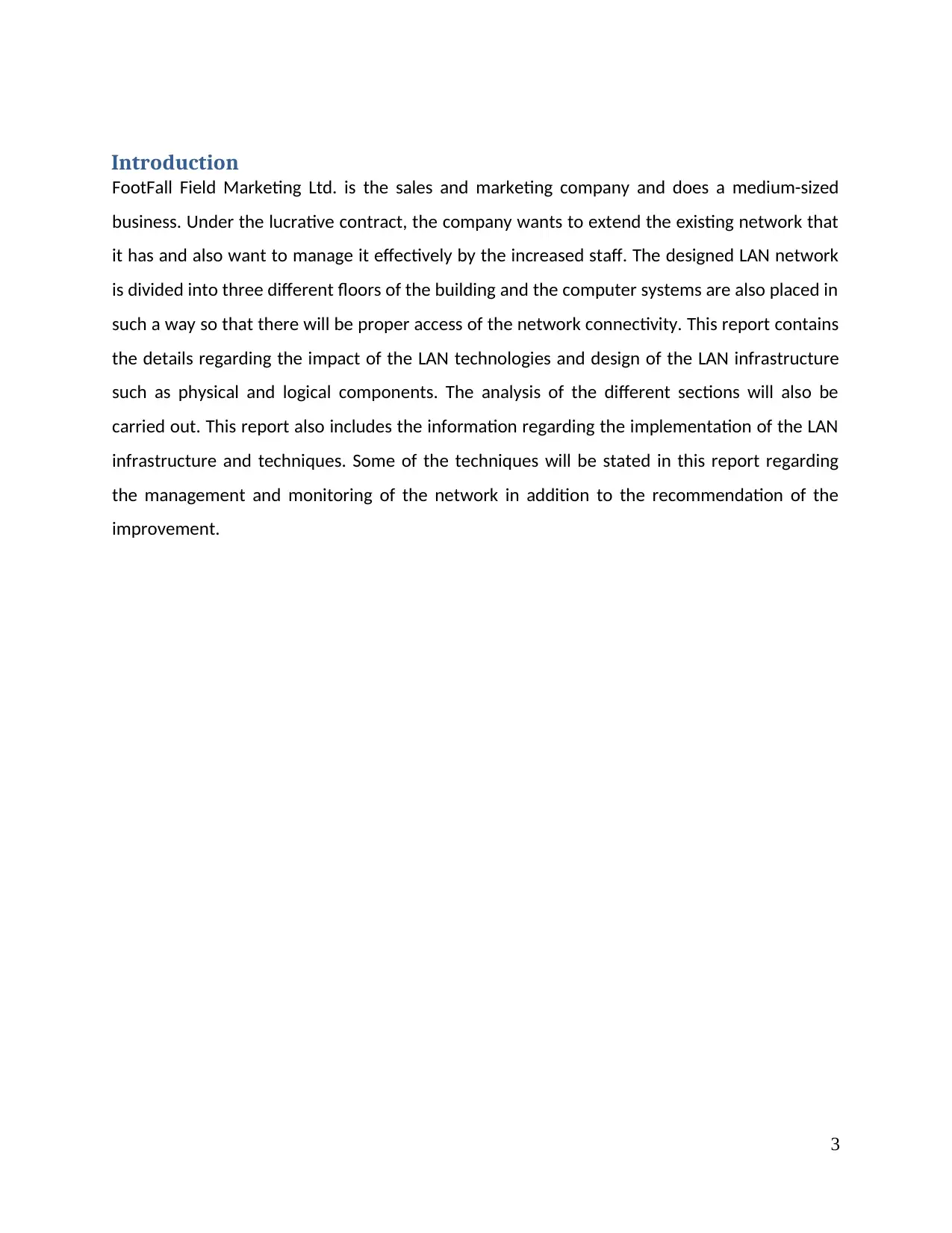
Introduction
FootFall Field Marketing Ltd. is the sales and marketing company and does a medium-sized
business. Under the lucrative contract, the company wants to extend the existing network that
it has and also want to manage it effectively by the increased staff. The designed LAN network
is divided into three different floors of the building and the computer systems are also placed in
such a way so that there will be proper access of the network connectivity. This report contains
the details regarding the impact of the LAN technologies and design of the LAN infrastructure
such as physical and logical components. The analysis of the different sections will also be
carried out. This report also includes the information regarding the implementation of the LAN
infrastructure and techniques. Some of the techniques will be stated in this report regarding
the management and monitoring of the network in addition to the recommendation of the
improvement.
3
Paraphrase This Document
Need a fresh take? Get an instant paraphrase of this document with our AI Paraphraser
LO1. Understand the impact of LAN technologies
A.C 1.1 critically evaluate different LAN technologies
LAN technologies:
IEEE 802 LAN standards
It is the networking standard that has been developed for maintaining the local area networks
and it is used on the basis of the global needs. It is basically used for the Ethernet and the
wireless local area networks. The protocol demonstrated in this standard maps the data link
layer and physical layer described in the reference model of OSI (D'Ambrosia, 2017).
IEEE 802.11 wireless standards
LAN technologies are cost-effective and are most important technologies which are driven by
IEEE802.11. This standard can be used in two different modes of network topology. This
standard is responsible for introducing the WEP protocol and security issues can be analysed
easily. WEP (Wired Equivalent Privacy) is responsible for the protection of the wireless
communication so that eavesdropping will not take place (Dhanalakshmi and Sathiya, 2015).
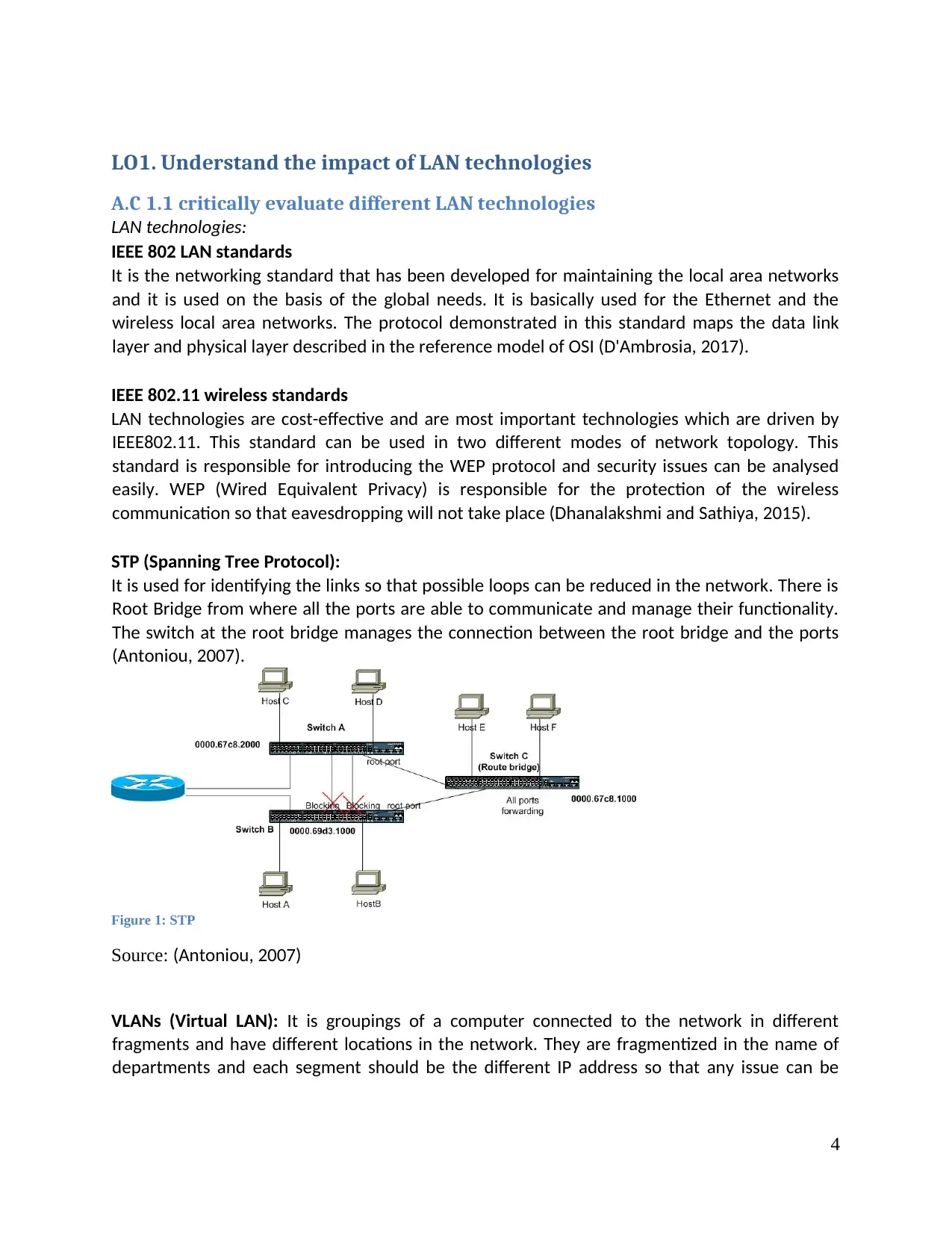
STP (Spanning Tree Protocol):
It is used for identifying the links so that possible loops can be reduced in the network. There is
Root Bridge from where all the ports are able to communicate and manage their functionality.
The switch at the root bridge manages the connection between the root bridge and the ports
(Antoniou, 2007).
Figure 1: STP
Source: (Antoniou, 2007)
VLANs (Virtual LAN): It is groupings of a computer connected to the network in different
fragments and have different locations in the network. They are fragmentized in the name of
departments and each segment should be the different IP address so that any issue can be
4
A.C 1.1 critically evaluate different LAN technologies
LAN technologies:
IEEE 802 LAN standards
It is the networking standard that has been developed for maintaining the local area networks
and it is used on the basis of the global needs. It is basically used for the Ethernet and the
wireless local area networks. The protocol demonstrated in this standard maps the data link
layer and physical layer described in the reference model of OSI (D'Ambrosia, 2017).
IEEE 802.11 wireless standards
LAN technologies are cost-effective and are most important technologies which are driven by
IEEE802.11. This standard can be used in two different modes of network topology. This
standard is responsible for introducing the WEP protocol and security issues can be analysed
easily. WEP (Wired Equivalent Privacy) is responsible for the protection of the wireless
communication so that eavesdropping will not take place (Dhanalakshmi and Sathiya, 2015).
STP (Spanning Tree Protocol):
It is used for identifying the links so that possible loops can be reduced in the network. There is
Root Bridge from where all the ports are able to communicate and manage their functionality.
The switch at the root bridge manages the connection between the root bridge and the ports
(Antoniou, 2007).
Figure 1: STP
Source: (Antoniou, 2007)
VLANs (Virtual LAN): It is groupings of a computer connected to the network in different
fragments and have different locations in the network. They are fragmentized in the name of
departments and each segment should be the different IP address so that any issue can be
4
detected in the LAN connection. It reduces the administration budget and increases the
flexibility in the network infrastructure (Peters, 2016).
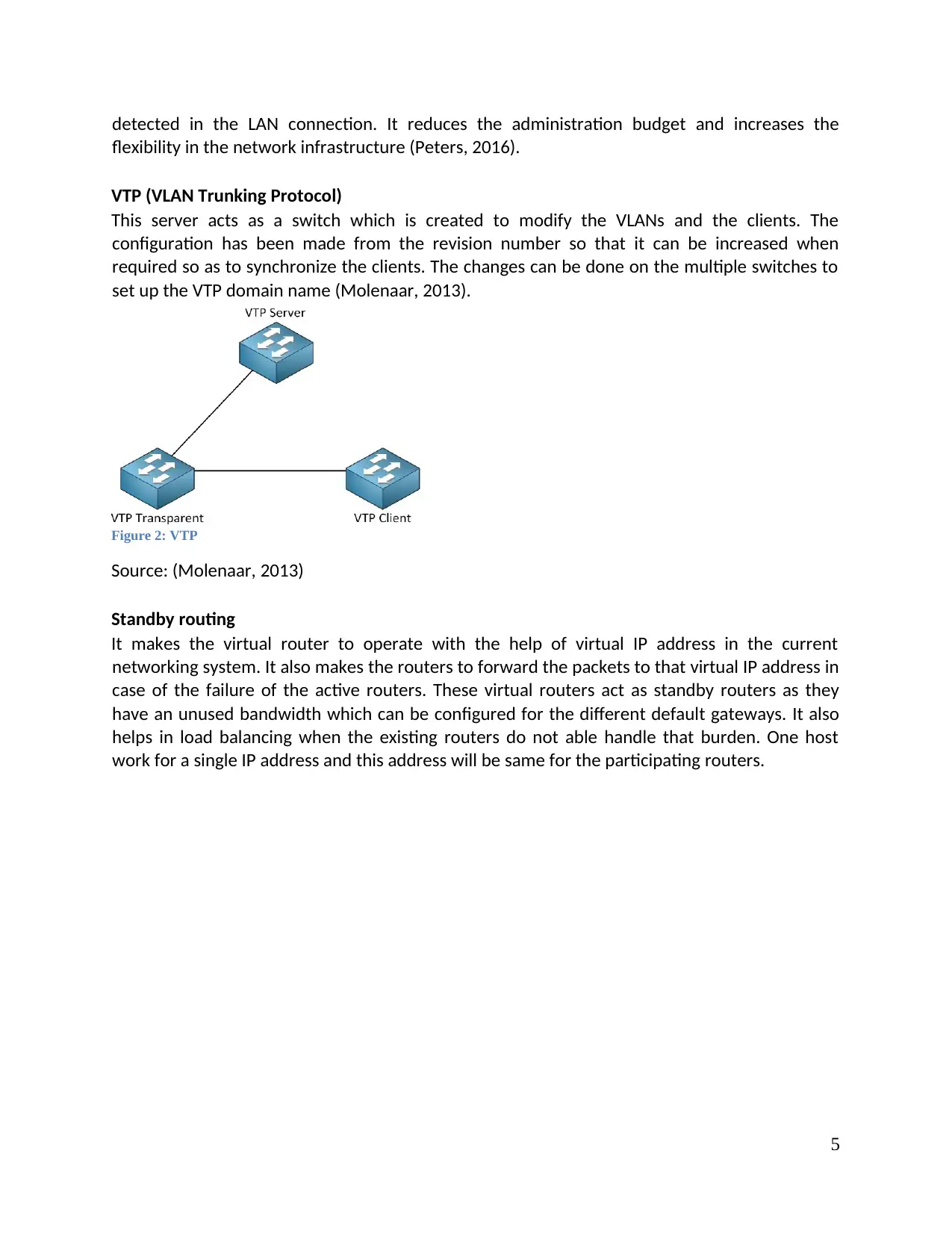
VTP (VLAN Trunking Protocol)
This server acts as a switch which is created to modify the VLANs and the clients. The
configuration has been made from the revision number so that it can be increased when
required so as to synchronize the clients. The changes can be done on the multiple switches to
set up the VTP domain name (Molenaar, 2013).
Figure 2: VTP
Source: (Molenaar, 2013)
Standby routing
It makes the virtual router to operate with the help of virtual IP address in the current
networking system. It also makes the routers to forward the packets to that virtual IP address in
case of the failure of the active routers. These virtual routers act as standby routers as they
have an unused bandwidth which can be configured for the different default gateways. It also
helps in load balancing when the existing routers do not able handle that burden. One host
work for a single IP address and this address will be same for the participating routers.
5
flexibility in the network infrastructure (Peters, 2016).
VTP (VLAN Trunking Protocol)
This server acts as a switch which is created to modify the VLANs and the clients. The
configuration has been made from the revision number so that it can be increased when
required so as to synchronize the clients. The changes can be done on the multiple switches to
set up the VTP domain name (Molenaar, 2013).
Figure 2: VTP
Source: (Molenaar, 2013)
Standby routing
It makes the virtual router to operate with the help of virtual IP address in the current
networking system. It also makes the routers to forward the packets to that virtual IP address in
case of the failure of the active routers. These virtual routers act as standby routers as they
have an unused bandwidth which can be configured for the different default gateways. It also
helps in load balancing when the existing routers do not able handle that burden. One host
work for a single IP address and this address will be same for the participating routers.
5
⊘ This is a preview!⊘
Do you want full access?
Subscribe today to unlock all pages.
Trusted by 1+ million students worldwide
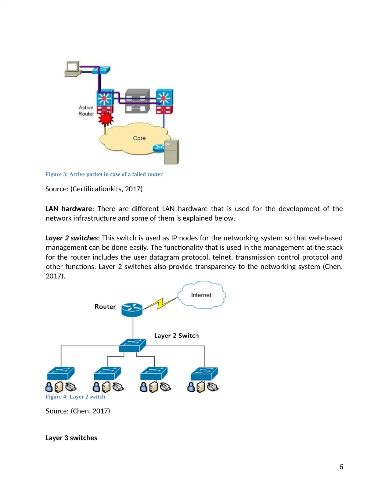
Figure 3: Active packet in case of a failed router
Source: (Certificationkits, 2017)
LAN hardware: There are different LAN hardware that is used for the development of the
network infrastructure and some of them is explained below.
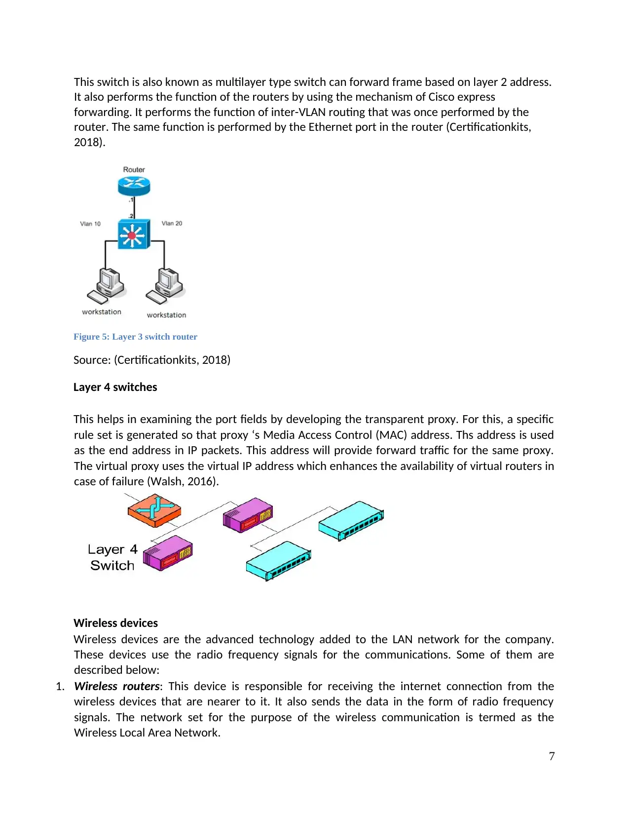
Layer 2 switches: This switch is used as IP nodes for the networking system so that web-based
management can be done easily. The functionality that is used in the management at the stack
for the router includes the user datagram protocol, telnet, transmission control protocol and
other functions. Layer 2 switches also provide transparency to the networking system (Chen,
2017).
Figure 4: Layer 2 switch
Source: (Chen, 2017)
Layer 3 switches
6
Source: (Certificationkits, 2017)
LAN hardware: There are different LAN hardware that is used for the development of the
network infrastructure and some of them is explained below.
Layer 2 switches: This switch is used as IP nodes for the networking system so that web-based
management can be done easily. The functionality that is used in the management at the stack
for the router includes the user datagram protocol, telnet, transmission control protocol and
other functions. Layer 2 switches also provide transparency to the networking system (Chen,
2017).
Figure 4: Layer 2 switch
Source: (Chen, 2017)
Layer 3 switches
6
Paraphrase This Document
Need a fresh take? Get an instant paraphrase of this document with our AI Paraphraser
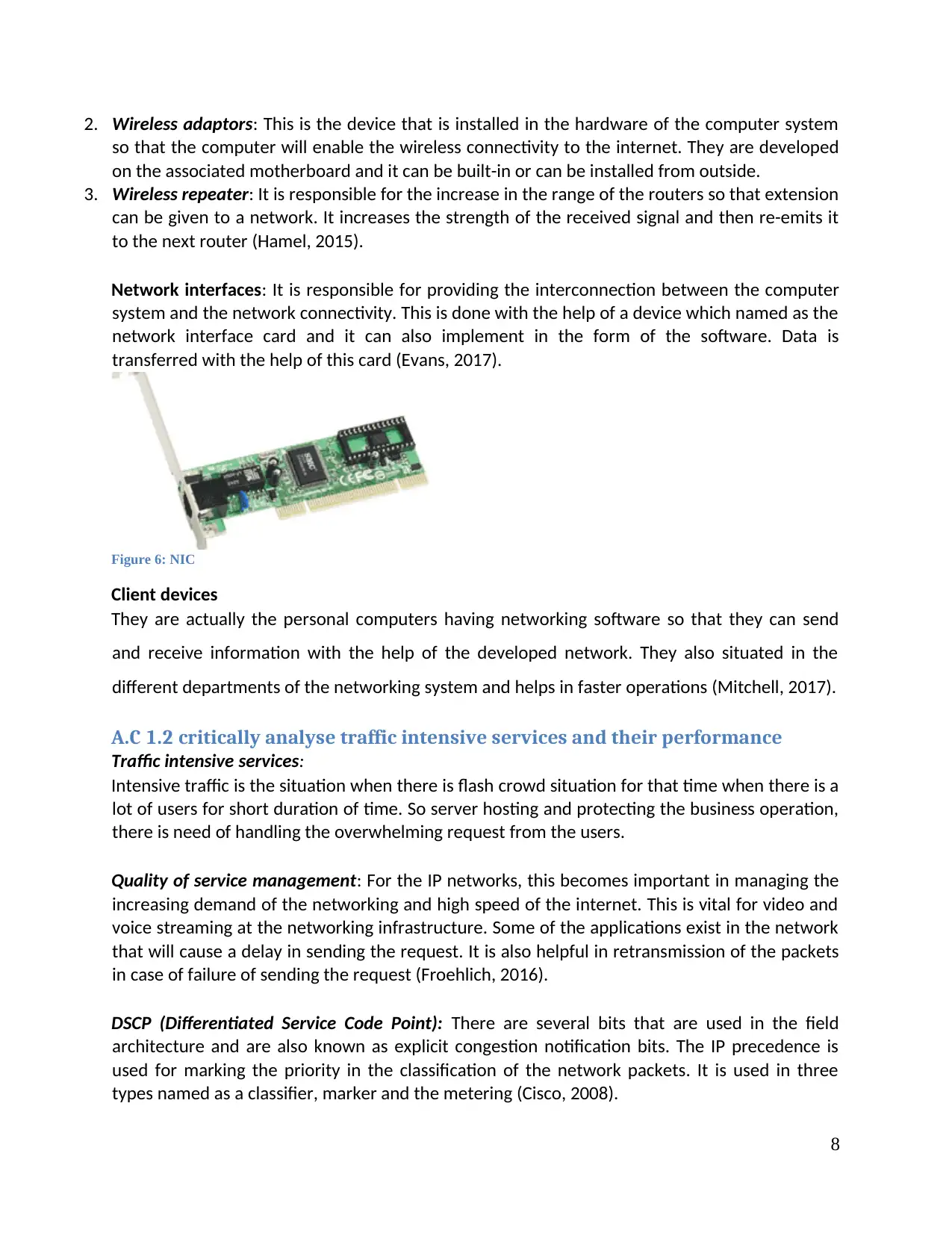
This switch is also known as multilayer type switch can forward frame based on layer 2 address.
It also performs the function of the routers by using the mechanism of Cisco express
forwarding. It performs the function of inter-VLAN routing that was once performed by the
router. The same function is performed by the Ethernet port in the router (Certificationkits,
2018).
Figure 5: Layer 3 switch router
Source: (Certificationkits, 2018)
Layer 4 switches
This helps in examining the port fields by developing the transparent proxy. For this, a specific
rule set is generated so that proxy ‘s Media Access Control (MAC) address. Ths address is used
as the end address in IP packets. This address will provide forward traffic for the same proxy.
The virtual proxy uses the virtual IP address which enhances the availability of virtual routers in
case of failure (Walsh, 2016).
Wireless devices
Wireless devices are the advanced technology added to the LAN network for the company.
These devices use the radio frequency signals for the communications. Some of them are
described below:
1. Wireless routers: This device is responsible for receiving the internet connection from the
wireless devices that are nearer to it. It also sends the data in the form of radio frequency
signals. The network set for the purpose of the wireless communication is termed as the
Wireless Local Area Network.
7
2. Wireless adaptors: This is the device that is installed in the hardware of the computer system
so that the computer will enable the wireless connectivity to the internet. They are developed
on the associated motherboard and it can be built-in or can be installed from outside.
3. Wireless repeater: It is responsible for the increase in the range of the routers so that extension
can be given to a network. It increases the strength of the received signal and then re-emits it
to the next router (Hamel, 2015).
Network interfaces: It is responsible for providing the interconnection between the computer
system and the network connectivity. This is done with the help of a device which named as the
network interface card and it can also implement in the form of the software. Data is
transferred with the help of this card (Evans, 2017).
Figure 6: NIC
Client devices
They are actually the personal computers having networking software so that they can send
and receive information with the help of the developed network. They also situated in the
different departments of the networking system and helps in faster operations (Mitchell, 2017).
A.C 1.2 critically analyse traffic intensive services and their performance
Traffic intensive services:
Intensive traffic is the situation when there is flash crowd situation for that time when there is a
lot of users for short duration of time. So server hosting and protecting the business operation,
there is need of handling the overwhelming request from the users.
Quality of service management: For the IP networks, this becomes important in managing the
increasing demand of the networking and high speed of the internet. This is vital for video and
voice streaming at the networking infrastructure. Some of the applications exist in the network
that will cause a delay in sending the request. It is also helpful in retransmission of the packets
in case of failure of sending the request (Froehlich, 2016).
DSCP (Differentiated Service Code Point): There are several bits that are used in the field
architecture and are also known as explicit congestion notification bits. The IP precedence is
used for marking the priority in the classification of the network packets. It is used in three
types named as a classifier, marker and the metering (Cisco, 2008).
8
⊘ This is a preview!⊘
Do you want full access?
Subscribe today to unlock all pages.
Trusted by 1+ million students worldwide
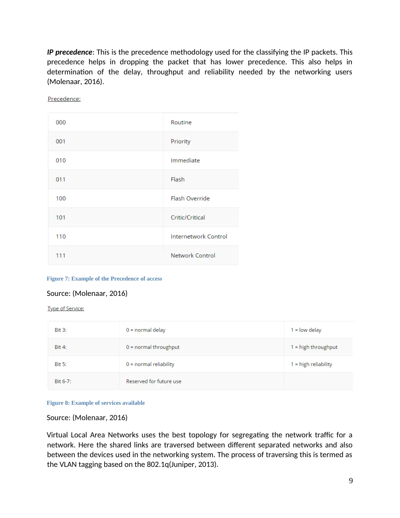
IP precedence: This is the precedence methodology used for the classifying the IP packets. This
precedence helps in dropping the packet that has lower precedence. This also helps in
determination of the delay, throughput and reliability needed by the networking users
(Molenaar, 2016).
Figure 7: Example of the Precedence of access
Source: (Molenaar, 2016)
Figure 8: Example of services available
Source: (Molenaar, 2016)
Virtual Local Area Networks uses the best topology for segregating the network traffic for a
network. Here the shared links are traversed between different separated networks and also
between the devices used in the networking system. The process of traversing this is termed as
the VLAN tagging based on the 802.1q(Juniper, 2013).
9
Paraphrase This Document
Need a fresh take? Get an instant paraphrase of this document with our AI Paraphraser
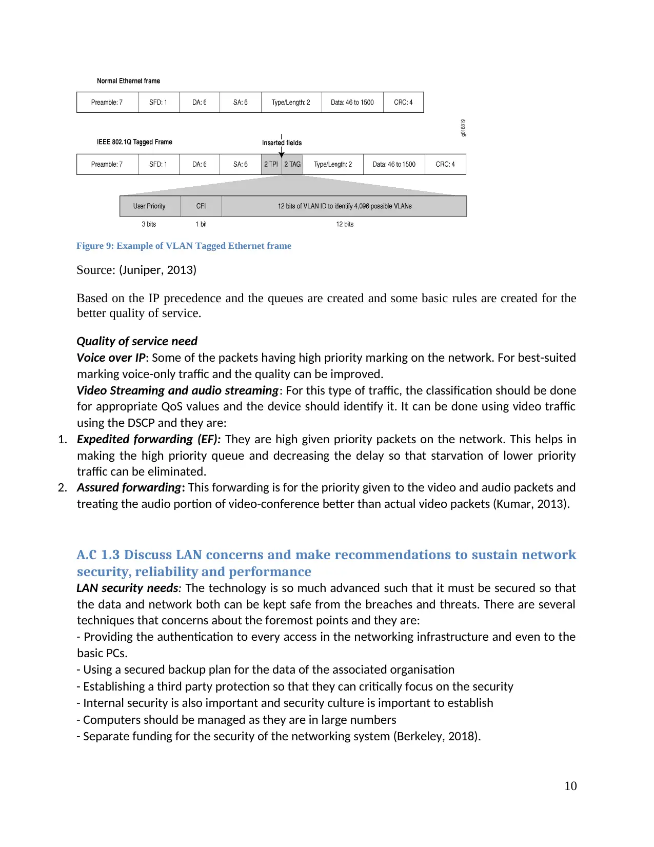
Figure 9: Example of VLAN Tagged Ethernet frame
Source: (Juniper, 2013)
Based on the IP precedence and the queues are created and some basic rules are created for the
better quality of service.
Quality of service need
Voice over IP: Some of the packets having high priority marking on the network. For best-suited
marking voice-only traffic and the quality can be improved.
Video Streaming and audio streaming: For this type of traffic, the classification should be done
for appropriate QoS values and the device should identify it. It can be done using video traffic
using the DSCP and they are:
1. Expedited forwarding (EF): They are high given priority packets on the network. This helps in
making the high priority queue and decreasing the delay so that starvation of lower priority
traffic can be eliminated.
2. Assured forwarding: This forwarding is for the priority given to the video and audio packets and
treating the audio portion of video-conference better than actual video packets (Kumar, 2013).
A.C 1.3 Discuss LAN concerns and make recommendations to sustain network
security, reliability and performance
LAN security needs: The technology is so much advanced such that it must be secured so that
the data and network both can be kept safe from the breaches and threats. There are several
techniques that concerns about the foremost points and they are:
- Providing the authentication to every access in the networking infrastructure and even to the
basic PCs.
- Using a secured backup plan for the data of the associated organisation
- Establishing a third party protection so that they can critically focus on the security
- Internal security is also important and security culture is important to establish
- Computers should be managed as they are in large numbers
- Separate funding for the security of the networking system (Berkeley, 2018).
10
Techniques that can be used for the security are:
Switch Port Control: This feature is disabled in the default setting of the switch ports and it is
necessary that it should be enabled on the interface. Firstly the privileged mode should be
enabled and then configure it. After this, the interface configuration modes is inserted and then
enable the switch port security (Wilkins, 2012).
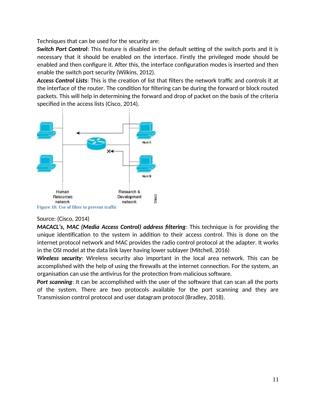
Access Control Lists: This is the creation of list that filters the network traffic and controls it at
the interface of the router. The condition for filtering can be during the forward or block routed
packets. This will help in determining the forward and drop of packet on the basis of the criteria
specified in the access lists (Cisco, 2014).
Figure 10: Use of filter to prevent traffic
Source: (Cisco, 2014)
MACACL’s, MAC (Media Access Control) address filtering: This technique is for providing the
unique identification to the system in addition to their access control. This is done on the
internet protocol network and MAC provides the radio control protocol at the adapter. It works
in the OSI model at the data link layer having lower sublayer (Mitchell, 2016)
Wireless security: Wireless security also important in the local area network. This can be
accomplished with the help of using the firewalls at the internet connection. For the system, an
organisation can use the antivirus for the protection from malicious software.
Port scanning: It can be accomplished with the user of the software that can scan all the ports
of the system. There are two protocols available for the port scanning and they are
Transmission control protocol and user datagram protocol (Bradley, 2018).
11
Switch Port Control: This feature is disabled in the default setting of the switch ports and it is
necessary that it should be enabled on the interface. Firstly the privileged mode should be
enabled and then configure it. After this, the interface configuration modes is inserted and then
enable the switch port security (Wilkins, 2012).
Access Control Lists: This is the creation of list that filters the network traffic and controls it at
the interface of the router. The condition for filtering can be during the forward or block routed
packets. This will help in determining the forward and drop of packet on the basis of the criteria
specified in the access lists (Cisco, 2014).
Figure 10: Use of filter to prevent traffic
Source: (Cisco, 2014)
MACACL’s, MAC (Media Access Control) address filtering: This technique is for providing the
unique identification to the system in addition to their access control. This is done on the
internet protocol network and MAC provides the radio control protocol at the adapter. It works
in the OSI model at the data link layer having lower sublayer (Mitchell, 2016)
Wireless security: Wireless security also important in the local area network. This can be
accomplished with the help of using the firewalls at the internet connection. For the system, an
organisation can use the antivirus for the protection from malicious software.
Port scanning: It can be accomplished with the user of the software that can scan all the ports
of the system. There are two protocols available for the port scanning and they are
Transmission control protocol and user datagram protocol (Bradley, 2018).
11
⊘ This is a preview!⊘
Do you want full access?
Subscribe today to unlock all pages.
Trusted by 1+ million students worldwide
1 out of 32
Related Documents


Your All-in-One AI-Powered Toolkit for Academic Success.
+13062052269
info@desklib.com
Available 24*7 on WhatsApp / Email
![[object Object]](/_next/static/media/star-bottom.7253800d.svg)
Unlock your academic potential
Copyright © 2020–2026 A2Z Services. All Rights Reserved. Developed and managed by ZUCOL.