Software Design Document for Lunar Rover Mapping Project Analysis
VerifiedAdded on 2020/02/18
|14
|3370
|295
Report
AI Summary
This Software Design Document details the Lunar Rover Mapping Project, which aims to develop a low-cost robotic system for lunar exploration. The project focuses on the design of crucial modules for sensing, navigation, and data recording using onboard sensors. The document covers the system's architecture, component decomposition, data design, and human interface, ensuring the rover can map the lunar surface, identify objects, and navigate complex terrains. Key aspects include the rover's ability to enter survey areas, create real-time maps, and transmit data back to Earth. The design incorporates safety measures, operational procedures, and progress tracking, with constraints related to the EV3 kit and stereo vision analysis. The document also outlines the rover's operational modes, safety protocols, and the importance of accurate mapping for successful space exploration. The project emphasizes the use of XML for data storage, and the creation of a user interface for remote operation and control. The document also includes architectural alternatives, design rationales, and resource estimates.
Software Design Document-Lunar Rover Mapping Project
Paraphrase This Document
Need a fresh take? Get an instant paraphrase of this document with our AI Paraphraser
Executive Summary
Lunar Rover is a vehicle for Space Explorations that is developed at a low-cost for the means
of transporting to the Moon with high precision soft landing. Lunar Rover Mapping Project is
to sense, navigate and record with sensors on-board. Objects such as debris and carters must
be found and recording should be done. Moon has terrestrial analogue environments like
deserts, craters or other surfaces on Earth. Lunar Rover must have the capacity to enter into
the survey area and survey map of the surface of the moon The Software Design is
concentrated in the crucial modules and base level functionality of the system. The system is
designed to elicit the requirements of the client for the EV3 kit.
.
Table of Contents
1. Introduction.............................................................................................................................2
1.1 Purpose.......................................................................................................................................3
1.2 Scope...........................................................................................................................................3
1.3 Constrains..................................................................................................................................3
2. System Overview......................................................................................................................3
2.1 The Rover Map..........................................................................................................................4
2.2 Survey area terrain representation for prototype...................................................................4
2.3 Operation...................................................................................................................................5
2.4 Safety..........................................................................................................................................5
2.5 Progress......................................................................................................................................5
3. System Architecture and Components Design.......................................................................6
3.1. Architectural Description.........................................................................................................6
3.2. Component Decomposition Description..................................................................................6
3.3. Detailed Components Design Description...............................................................................6
3.4. Architectural Alternatives........................................................................................................6
3.5. Design Rationale.......................................................................................................................6
4. Data Design..............................................................................................................................6
4.1 Data Structures..........................................................................................................................6
5. Design Details...........................................................................................................................6
5.1 Class Diagrams..........................................................................................................................6
5.2 State diagrams...........................................................................................................................6
5.3 Interaction Diagrams.................................................................................................................6
6. Human Interface Design.........................................................................................................7
6.1 Overview of the User Interface.................................................................................................7
6.2 Detailed Design of the User Interface.......................................................................................7
7. Resource Estimates..................................................................................................................7
8. Definitions, Acronyms, and Abbreviations............................................................................7
9. Conclusions..............................................................................................................................7
⊘ This is a preview!⊘
Do you want full access?
Subscribe today to unlock all pages.
Trusted by 1+ million students worldwide
1. Introduction
In the early history of earth and other rocky planets moon plays a significant interface.
The Software design document determination is to provide a low-level description about
Lunar Rover Mapping Project offering intuition in the design and structure of each module.
The following are the topics include
System Architecture
Component diagram
Over view of User interface design
Data flow design
Human interface description.
1.1 Purpose
The purpose of Lunar Rover Mapping Project is to provide a low cost method for
robotic space exploration. To locate the Lunar Rover Robot on the surface of the moon that
travel 500mts and to broadcast the images and video of the moon to the earth in return. The
vehicle is also developed for transporting it with high precision along with soft landing.
1.2 Scope
The Software Design is concentrated in the crucial modules and base level
functionality of the system. The Software Design Development works as base level
perception that is a proof concept for building the Lunar Rover Mapping. The scope of Lunar
Rover Mapping Project is to sense, navigate and record with sensors on-board. Objects such
as debris and carters must be found and recording should be done. The concept of GPS
painting is also utilizes for the bounding the surface of the moon to provide a full coverage of
the survey map.
1.3 Constrains
The major constrain is to match the algorithm of Lunar Rover and its navigation to be
presented on a stereo vision system analysis and Lunar Rover on a working environment. The
wavelet transform are extracted along with the feature-matching phase of the edge points and
they are used as matching primitives. To select the correct matching spots with strategy of
pyramidal searching criterions are used. It results in helping the algorithm to find its
matching spots correctly even for a large number of edge points. Fairly high accuracy of
results of experiments are provided with the real images of terrain with natural to indicate
that the algorithm gives disparity in dense. The natural terrain must hold the algorithm that
Paraphrase This Document
Need a fresh take? Get an instant paraphrase of this document with our AI Paraphraser
hold the geometry constrain and pyramidal searching. To arrive at the satisfactory solution it
is not sufficient to have a stereo matching which is a complex problem and information of the
image. Several geometric constrains are adopted in this algorithm to reduce the false matches.
It hold the responsibility to fulfil the requirement for the EV3 kit provided
2. System Overview
The system is designed to elicit the requirements of the client for the EV3 kit. The major
requirement of the vehicle is to have the capacity to enter the survey area and to create a
survey map. The design is to locate smoothly on the mapped point to another. A Rover map
is designed for the smooth locating of the Lunar Rover. The map should contain the entire
survey map over view and it makes an easy operating methods for the operator. It also have
the visual operating facility for the operator. The foremost concept of the Software design
Development is to analyse the requirements and to make plans for what to be done and what
not to. It is fundamentally featuring the need of the software. It gives the basic specifications
that is required for the Software Design Development and the requirements that is required
initially.
2.1 The Rover Map
The major requirement is that the Lunar Rover must have the capacity to enter into the
survey area and survey map of the surface of the moon must be created. The map that is
given must be designed in a real time and demonstrate location of the Lunar Rover at the
current stage, details of any significant topographies found in case and show the difference of
the mapped and the unmapped locations in the moon’s surface. This is done because the
mapping technique may take a reasonable quantity of time and catastrophes can even occur in
situation of exploration of space, it is essential that the mapping process that is done should
take the partial or complete utilization of the software which is used. So that this may lead to
the smooth landing of the Lunar Rover.
The mapping that is done stores the data in the XML layout that has been requested by
the CTO. An external developer will make the mapping database for the DTD. The
availability is made after the completion of the DTD. A simple XML format is made so that
the arrival of DTD confirmation is made. The formation of this kind of layout is considered
to be an important module for the success of the company co-operate with other teams in the
Software Systems. The entire survey area must be shown by the map and techniques should
be implemented to zoom the particular area by the operator.
2.2 Survey area terrain representation for prototype
The representation of terrain constrain is built for the development of the prototype, a
paper or cars will be used for this. Their size will be no longer than the A1 sheet of paper and
the size will be around 4.65 room of a SEP Lab. Boundaries are the main elements of the
terrain, tracks/trail will be indicated by the coloured lines, areas that are coloured indicate the
radiations and objects that may interrelate with the Lunar Rover. The machinist of the vehicle
is designate for no-go zones (NGZ) that showing potentially treacherous zones of the survey
map where the Lunar Rover must not to enter. Occurrence of the debris or dangerous
environmental incongruities to ensue between the site that is selected and point of arrival.
The frontier is rectangular, that is marked on the surface as a line of a uniform colour. An
unexpected conversions in the terrain gradient (i.e. craters) will be embodied as a dense line.
If the line is passed by three wheels of the vehicle, it is unlikely that the vehicle will
recuperate without backing. The operator can see through delayed video of the vehicle who
works remotely on Earth and he is responsible to feed on the Lunar Rover and orbit satellite
whit low. When the vehicle has proficient the 3rd mission, impulsively clogged he survey, the
vehicle must arrive to the Lunar Rover arrival site and await for further command.
2.3 Operation
The machinist has some form of pictorial shadowing of the Lunar Rover operations.
The machinist must also have the capability to mark NGZ at any time on both mapped and
areas which are not mapped of the site. The machinist ask the Lunar Rover to passage
instantly to a given point on the survey area at any time. The mostly concerned with the
accuracy of the mapped representation is rather than not taking Lunar Rover as it is just a
space race. Prototype must be evaluated for the mapping of survey area. The machinist is
necessary to have the capacity to communicate instantly if any unsafe condition is detected to
stop the vehicle.
2.4 Safety
Safety is the major essential concept for the Software Design Development. It has
many safety issues that is to be described in the project. In order to protect the expensive
Lunar Rover from hazardous situation. There are many safety issues which must be addressed
in this project. To protect the destruction along to preservation of the vehicle from the site
integrity it must not strike in contradiction of any external body in a significant force.
Subsequently the landing of the vehicle to the site, the system may move the vehicle to an
⊘ This is a preview!⊘
Do you want full access?
Subscribe today to unlock all pages.
Trusted by 1+ million students worldwide
applicable starting site before starting a survey safely under manual control of the machinist.
The machinist may take a manual control of the vehicle if considered necessary for
preliminary setup.
2.5 Progress
Responsibility for ensuring the group delivers on the requirement, on budget and on
time. For this solution, it is necessary to generate and document progress data on a weekly
basis. To know hours worked on projects the in-line with common industry practice is made.
Every group is to submit a statement setting out the relative at the end of the course for the
contribution of every group member to the overall of the project.
3. System Architecture and Components Design
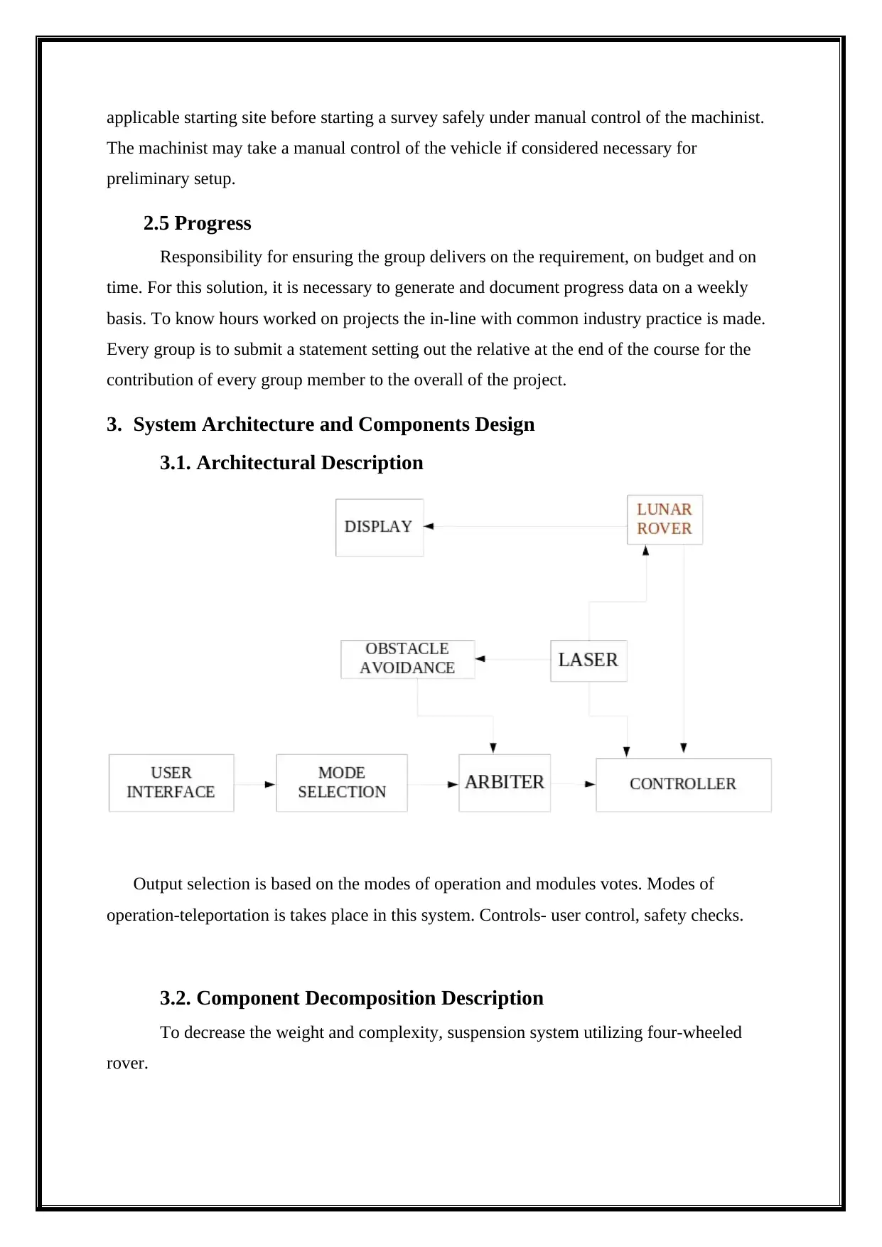
3.1. Architectural Description
Output selection is based on the modes of operation and modules votes. Modes of
operation-teleportation is takes place in this system. Controls- user control, safety checks.
3.2. Component Decomposition Description
To decrease the weight and complexity, suspension system utilizing four-wheeled
rover.
The machinist may take a manual control of the vehicle if considered necessary for
preliminary setup.
2.5 Progress
Responsibility for ensuring the group delivers on the requirement, on budget and on
time. For this solution, it is necessary to generate and document progress data on a weekly
basis. To know hours worked on projects the in-line with common industry practice is made.
Every group is to submit a statement setting out the relative at the end of the course for the
contribution of every group member to the overall of the project.
3. System Architecture and Components Design
3.1. Architectural Description
Output selection is based on the modes of operation and modules votes. Modes of
operation-teleportation is takes place in this system. Controls- user control, safety checks.
3.2. Component Decomposition Description
To decrease the weight and complexity, suspension system utilizing four-wheeled
rover.
Paraphrase This Document
Need a fresh take? Get an instant paraphrase of this document with our AI Paraphraser
3.3. Detailed Components Design Description
Purpose: The vehicle is also developed for transporting it with high precision along with
soft landing. The requirement specification (SRS) that was given.
Function: To characterize terrain several approaches can be used for clear description.
Combining of shear strength and normal are included in the measuring.
Subordinates: The smooth landing of the Lunar Rover is done with the variety of
subordinates are used.
Dependencies: Constrain is defined to match the algorithm of Lunar Rover and its
navigation to be presented on a stereo vision system analysis and Lunar Rover on a working
environment. The matching primitives are derived from the wavelet transform are extracted
along with the feature-matching phase of the edge points and they are used as matching
primitives.
Interfaces: User inter face is used for the easy access of the machinist.
Data: It is highly recommended for the use of LeJOS java programming for the launching
or the Lunar Vehicle.
3.4. Architectural Alternatives
Execution of tasks is enabled in parallel manner and single point failures would be
performed. An architecture defines the allocation of interfaces, structural of interfaces and
functions of information. A surface probe defines, the probe concept of modularity.
Understanding the suite of system is necessary for analysing the functioning of the various
architectural trade options. To ensure the layout the architectural that are being analysed
should be given that are both feasible and viable for future vision the current and near-term
capabilities are necessary to be identified. The launching of the Lunar Rover were described
in different section. The payload masses to Lunar Rover are considered as the values that
represent the margin and the adapter.
Orion Service Module (SM)
Braking Stage (either Orion SM or a Large Storable Stage (LSS))
Orion Crew Module (CM)
Cryogenic Propulsive Stage (CPS)
Orbit Transfer Vehicle (OTV)
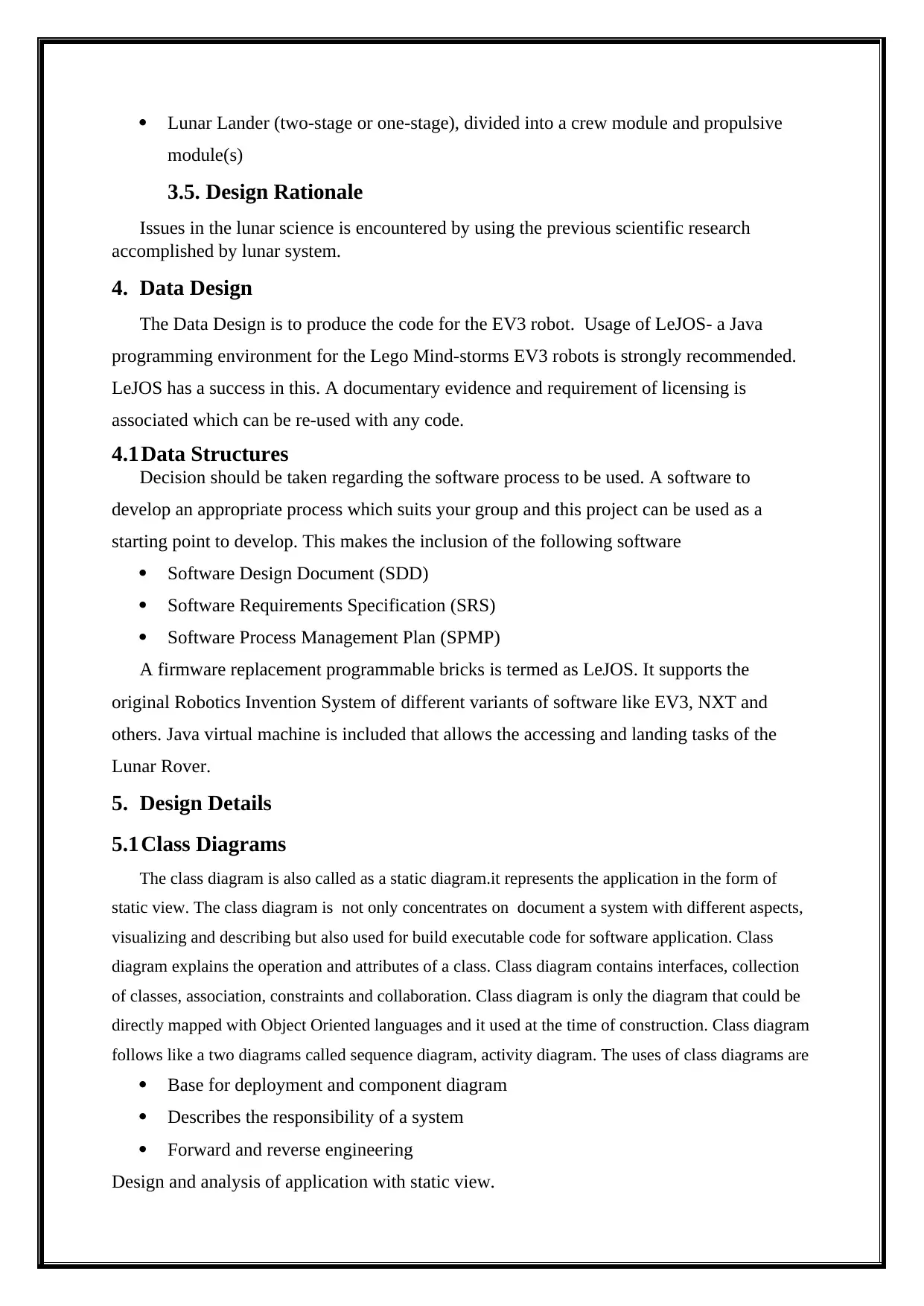
Lunar Lander (two-stage or one-stage), divided into a crew module and propulsive
module(s)
3.5. Design Rationale
Issues in the lunar science is encountered by using the previous scientific research
accomplished by lunar system.
4. Data Design
The Data Design is to produce the code for the EV3 robot. Usage of LeJOS- a Java
programming environment for the Lego Mind-storms EV3 robots is strongly recommended.
LeJOS has a success in this. A documentary evidence and requirement of licensing is
associated which can be re-used with any code.
4.1Data Structures
Decision should be taken regarding the software process to be used. A software to
develop an appropriate process which suits your group and this project can be used as a
starting point to develop. This makes the inclusion of the following software
Software Design Document (SDD)
Software Requirements Specification (SRS)
Software Process Management Plan (SPMP)
A firmware replacement programmable bricks is termed as LeJOS. It supports the
original Robotics Invention System of different variants of software like EV3, NXT and
others. Java virtual machine is included that allows the accessing and landing tasks of the
Lunar Rover.
5. Design Details
5.1Class Diagrams
The class diagram is also called as a static diagram.it represents the application in the form of
static view. The class diagram is not only concentrates on document a system with different aspects,
visualizing and describing but also used for build executable code for software application. Class
diagram explains the operation and attributes of a class. Class diagram contains interfaces, collection
of classes, association, constraints and collaboration. Class diagram is only the diagram that could be
directly mapped with Object Oriented languages and it used at the time of construction. Class diagram
follows like a two diagrams called sequence diagram, activity diagram. The uses of class diagrams are
Base for deployment and component diagram
Describes the responsibility of a system
Forward and reverse engineering
Design and analysis of application with static view.
⊘ This is a preview!⊘
Do you want full access?
Subscribe today to unlock all pages.
Trusted by 1+ million students worldwide
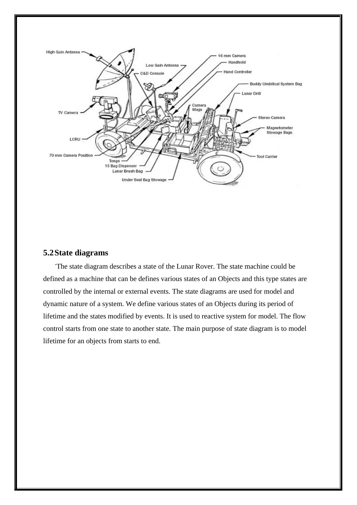
5.2State diagrams
`The state diagram describes a state of the Lunar Rover. The state machine could be
defined as a machine that can be defines various states of an Objects and this type states are
controlled by the internal or external events. The state diagrams are used for model and
dynamic nature of a system. We define various states of an Objects during its period of
lifetime and the states modified by events. It is used to reactive system for model. The flow
control starts from one state to another state. The main purpose of state diagram is to model
lifetime for an objects from starts to end.
Paraphrase This Document
Need a fresh take? Get an instant paraphrase of this document with our AI Paraphraser
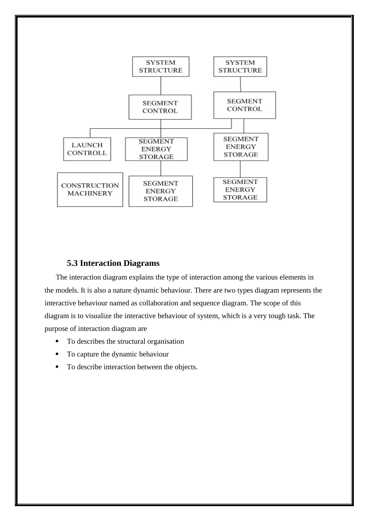
5.3 Interaction Diagrams
The interaction diagram explains the type of interaction among the various elements in
the models. It is also a nature dynamic behaviour. There are two types diagram represents the
interactive behaviour named as collaboration and sequence diagram. The scope of this
diagram is to visualize the interactive behaviour of system, which is a very tough task. The
purpose of interaction diagram are
To describes the structural organisation
To capture the dynamic behaviour
To describe interaction between the objects.
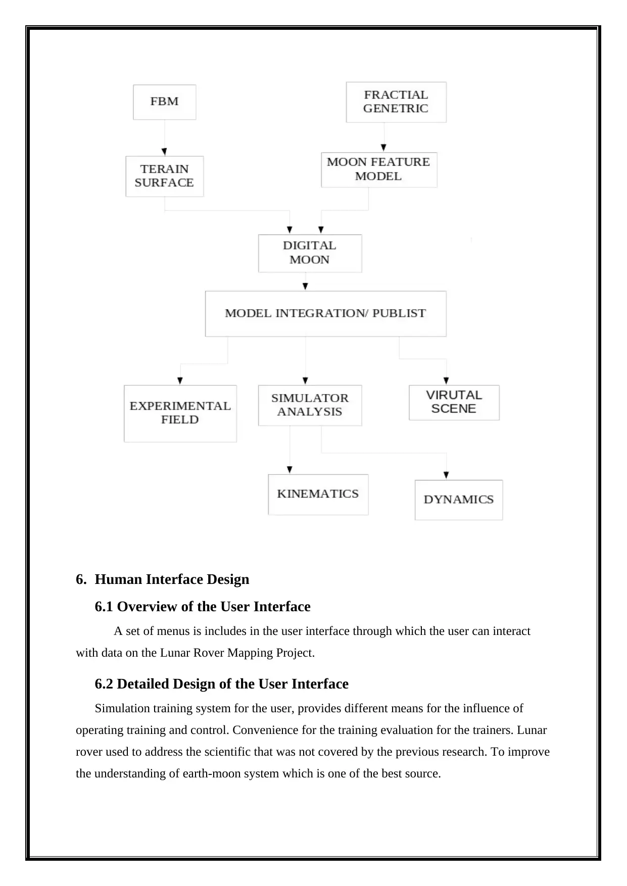
6. Human Interface Design
6.1 Overview of the User Interface
A set of menus is includes in the user interface through which the user can interact
with data on the Lunar Rover Mapping Project.
6.2 Detailed Design of the User Interface
Simulation training system for the user, provides different means for the influence of
operating training and control. Convenience for the training evaluation for the trainers. Lunar
rover used to address the scientific that was not covered by the previous research. To improve
the understanding of earth-moon system which is one of the best source.
⊘ This is a preview!⊘
Do you want full access?
Subscribe today to unlock all pages.
Trusted by 1+ million students worldwide
1 out of 14
Related Documents


Your All-in-One AI-Powered Toolkit for Academic Success.
+13062052269
info@desklib.com
Available 24*7 on WhatsApp / Email
![[object Object]](/_next/static/media/star-bottom.7253800d.svg)
Unlock your academic potential
Copyright © 2020–2026 A2Z Services. All Rights Reserved. Developed and managed by ZUCOL.