Analyzing MARIE Assembly Code, Instruction Sets, and Addressing

Verified

Added on  2021/05/31

|7
|769
|65
Homework Assignment
AI Summary
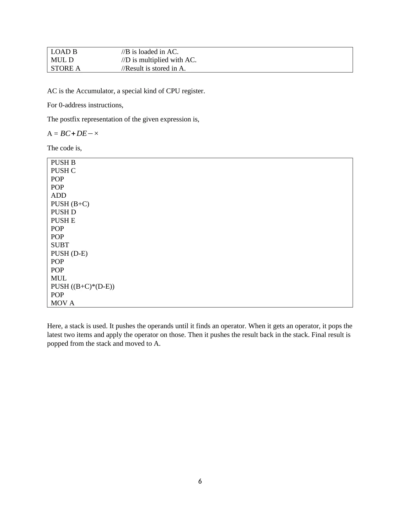
This document presents a comprehensive solution to a computer organization assignment, focusing on MARIE assembly language. The solution begins with the MARIE code for calculating the Nth Fibonacci number, analyzing its functionality and limitations, particularly addressing overflow issues. It then delves into instruction set architectures, detailing the calculation of instruction counts for 2-address, 1-address, and 0-address instructions based on the given bit size and address field lengths. The assignment further explores the conversion of an arithmetic expression into assembly code for 3-address, 2-address, 1-address, and 0-address machines, including the use of registers, accumulators, and stack-based operations with postfix notation. Finally, the solution references the textbook 'The Essentials of Computer Organization and Architecture' by Null and Lobur, providing a solid foundation in computer architecture concepts. This document is available on Desklib, a platform providing students with AI-based study tools, offering valuable insights into computer organization principles and practical assembly language programming.
Document Page
Title Page
1
tabler-icon-diamond-filled.svg

Paraphrase This Document

Need a fresh take? Get an instant paraphrase of this document with our AI Paraphraser
Document Page
Table of Contents
Question 1...................................................................................................................................................3
Question 2...................................................................................................................................................5
Question 3...................................................................................................................................................5
References...................................................................................................................................................7
2
Document Page
Question 1
a. The MARIE code for counting the Nth Fibonacci number is,
ORG 100
CLEAR //clears the accumulator.
INPUT // User input for the Nth Fibonacci number.
SUBT ONE // As Fibonacci series starts from 0th number, so that is adjusted.
STORE CTR
LOOP1, CLEAR //loop for counting the Fibonacci number.
LOAD CTR
SUBT ONE //updates the counter.
STORE CTR
LOAD S2
STORE S3
LOAD S2
ADD S1
STORE S2
LOAD S3
STORE S1 //updates S1 and S2. The adjacent Fibonacci numbers on each iteration of the loop.
LOAD CTR
SKIPCOND 400 //The loop runs until the counter becomes 0.
JUMP LOOP1
LOAD S2
OUTPUT //Prints the final output.
HALT
ONE, DEC 1
CTR, DEC 0
S2, DEC 1
S1, DEC 0
S3, DEC 0
The output,
The 16th Fibonacci number is counted as,
3
Document Page
The 23rd Fibonacci number is counted as,
b. The program produce right output till 23rd Fibonacci number. It produces wrong output for the
24th Fibonacci number and onwards. This is because MARIE simulator is a basic CPU simulator
4
tabler-icon-diamond-filled.svg

Paraphrase This Document

Need a fresh take? Get an instant paraphrase of this document with our AI Paraphraser
Document Page
that has limitations on the counting and processing capabilities. The registers overflow when the
Fibonacci number series advances. So, it produces wrong results.
Question 2
Given information are,
The instruction set size is, 11 bits.
Each address field is 4 bits long.
The number of 2-address instructions is 6.
So, each instruction has ( 2 ×4 )=8 bits occupied for addresses. Rest (11-8) = 3 bits are used for opcode.
The number of 1-address instructions is 30.
So, each instruction has 4 bits occupied for addresses and rest (11-4) = 7 bits used for operand.
So, the number of possible 0-address instructions is, (2¿¿ 11 ( 28 × 6 ) (24 ×30 ))=32¿ as no bits will
be used for address part.
Question 3
The given expression is, A=(B+C) ×(DE)
For the 3-address machine,
ADD R1, B, C // It will add B and C and store the result into R1.
SUBT R2, D, E //It will subtract E from D and put the result in R2.
MUL A, R1, R2 //It will multiply R1 and R2, the final result will be stored in A.
Here, R1 and R2 are two registers used for intermediate calculations.
For the 2-address machine,
MOV R1, B // It moves the value from B to R1.
ADD R1, C // It adds the value of C to R1 and puts the result in R1.
MOV R2, D // It moves the value from D to R2.
SUBT R2, E //It subtracts the value of E from R2. Then the result is stored in R2.
MUL R1, R2 // It multiplies R1 and R2. Then stores the value in R1.
MOV A, R1 // It moves the value of R1 to A.
Here, R1 and R2 are intermediate registers.
For 1-address machine,
LOAD B // B is loaded into AC.
ADD C // C is added to AC.
STORE B // Result is stored in B
LOAD D //D is loaded in AC.
SUBT E //E is subtracted from AC.
STORE D //Result is stored in D.
5
Document Page
LOAD B //B is loaded in AC.
MUL D //D is multiplied with AC.
STORE A //Result is stored in A.
AC is the Accumulator, a special kind of CPU register.
For 0-address instructions,
The postfix representation of the given expression is,
A = BC+ DE×
The code is,
PUSH B
PUSH C
POP
POP
ADD
PUSH (B+C)
PUSH D
PUSH E
POP
POP
SUBT
PUSH (D-E)
POP
POP
MUL
PUSH ((B+C)*(D-E))
POP
MOV A
Here, a stack is used. It pushes the operands until it finds an operator. When it gets an operator, it pops the
latest two items and apply the operator on those. Then it pushes the result back in the stack. Final result is
popped from the stack and moved to A.
6
Document Page
References
Null, L., & Lobur, J. (2014). The Essentials of Computer Organization and Architecture. Jones & Bartlett
Publishers.
7
chevron_up_icon
1 out of 7
circle_padding
hide_on_mobile
zoom_out_icon
[object Object]