Analysis of Fatigue Failure and Material Selection in Engineering
VerifiedAdded on 2020/04/21
|14
|1666
|99
Report
AI Summary
This report presents an analysis of material selection in several engineering case studies. It begins with a critical analysis of the abnormal fatigue of a forklift fork, examining the failure mechanisms, fractographic analysis, and metallographic evaluations. The study identifies fatigue cracking and overload as key factors contributing to the failure. The report then investigates the fatigue cracking of a high-pressure oil tube, detailing the experimental procedures, results, and conclusions regarding the failure. Finally, the report includes a material selection project focusing on steel-concrete structures, discussing the performance index, material properties, and the advantages of steel-concrete in submerged tunnel construction. The report utilizes various references to support the analysis and findings.
MATERIAL SELECTION
By Name
Course
Instructor
Institution
Location
Date
By Name
Course
Instructor
Institution
Location
Date
Paraphrase This Document
Need a fresh take? Get an instant paraphrase of this document with our AI Paraphraser
Question 1
Critical analysis of engineering case study.
Analysis of the abnormal fatigue of the forklift fork
Abstract
This work covers the analysis of the abnormal fatigue of the forklift fork. Due to the abrupt
overload fracture, there is going to be failure mechanisms that cause this failure. At the outer part of
the compression zone, cracking is seen that is due to the fatigue fracture. The last failure is greatly
propelled by the cracking on the surface that is caused by fatigue strength.
Introduction
The fatigue failure mechanisms are caused by the cyclic loading that takes place under the
usual conditions of operation in a machine. The production of the raw material are conveyed by the
use of the forklift to the storage and the final production. Some loads that are supporting the forklift
fork are passed through stress repetitively with the variations in the load frequencies and the
vibrations caused by the conditions of the terrains. The condition for fatigue cracking is represent
weld repair of the forklift fork. Induction of the fatigue failure is done by the overloading conditions
(Holleck, 2011).
Procedures
This test was done by the used f the Nikon SMZ 1500 stereomicroscope. An inspection was
conducted on this material to the surface and the morphology. Along the cross-sectional area of the
microstructure of the material, using the abrasive SiC paper some grinding was conducted on the
material then the fining of the graded material is done by the use of the suspension of the silicon
and the diamond. By the use of the Nikon Epiphot 300, a metallographic analysis is done. The
testing of the hardness of the material is done by the Instro-Wolpert Vickers (Brunette, 2012).
Results
Chemical analysis
The analysis by the use of Spectroscopy showed that the fork was made of the steel
structural grade 34Cr4 this material is an alloy that is treatable and is normally used in the
fabrication of the shaft and in the machine axial.
Fractographic analysis
The identification of the fracture mechanisms can be done by the use of the fractographic
analysis. There are patterns that represent that structure of the surface that determines the fatigue
bending mechanism. In the outer part of the fork, there was orientation off the fatigue area that
suggested the occurring of the crack at the surface. Some of the characteristics were identified by
the proper assessment of the surface fracture. The consistency is seen on the fatigue mechanism in
terms of the bending unidirectional.
Evaluation Metallographically
There was an indication of the hardened microstructure from the optical micro-graphics of
the cross-sectional section that is polished and etched. But a decarburized area is prolonged to a
depth of about 200 is obtained at the outer part of the fork surface. The circular ferrite is found at
the core of the fork which is subdivided in microferites and was indicated during the metallographic
evaluation (Heremans, 2009).
Testing of the hardness and the analysis of the stress.
The use of the Rockwell C was applied in the testing of the hardness. The correspondence of
the steel hardness and the microstructure was identified. The hardness at the outer part of the core
was seen and recorded as indicated below. There was also correspondence of the average hardness
with that of the tensile strength (Callister, 2011).
⊘ This is a preview!⊘
Do you want full access?
Subscribe today to unlock all pages.

Trusted by 1+ million students worldwide
Conclusion
The abnormal failure of the forklift fork was due to the overload. This was indicated in the
Factograhic analysis, where the failure occurred under the following conditions i.e. the
concentration of stress and the condition of the service loading.
At the canter area of the fork, there was the existence of the cracks that led to the abdominal failure.
There were also a number of cracks experience at the outer part of the fork this also shown the fact
of the failure of the forklift fork (Çalışkan, 2013).
Fatigue cracking of high-pressure oil tube
Introduction
The oil tube composed of the high pressure and has a diameter of about 50mm and the
thickness of 4mm has been seen failed prematurely due to the crack on its longitude. The realization
of this failure was seen after some time. This tube is used as the unit of the hydraulic power. The
pressure within the tube was estimated to be 20MPa at 25oC temperature. Practically there was
variation in the pressure between 16 to 20MPa and occurrence of the shutdown is rarely seen
(Berenstein, 2011).
Experiment
The test of the failure was done by the non-destructive test. The discontinuity in the tube
was detected in the tube by the radiography. The ferristoscope was then used to detect the
magnitude of the magnetic phase in a separate area of the tube. When the testing of the tube has
been done the tube was the separated from the region for the analysis. The cracks were then
detected in the surfaces of the tube, cutting done to this surfaces and preservation of this surfaces
were also done.
Results
There was increase in the mean stress due to the welding residue, this is given by;
Paraphrase This Document
Need a fresh take? Get an instant paraphrase of this document with our AI Paraphraser
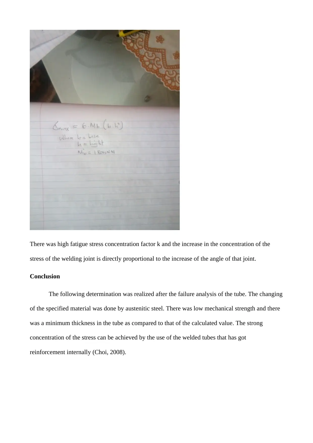
There was high fatigue stress concentration factor k and the increase in the concentration of the
stress of the welding joint is directly proportional to the increase of the angle of that joint.
Conclusion
The following determination was realized after the failure analysis of the tube. The changing
of the specified material was done by austenitic steel. There was low mechanical strength and there
was a minimum thickness in the tube as compared to that of the calculated value. The strong
concentration of the stress can be achieved by the use of the welded tubes that has got
reinforcement internally (Choi, 2008).
Question 2.
Material selection project
Steel-concrete
Introduction
Materials for constructions should flexible to design and make a physical object. This
flexibility is aimed at minimizing the cost of the production and improving the performance goals
of the product.
Performance index.
The steel-concrete performance is based on the fact that it has a poor thermal conductivity. At any
given temperature there is the minimization of the heat transfer by the steel. The selection of the
steel is also based on the stiffness and it's lighter weight that leads to it having a lower density with
higher Young's module. The density of the steel is given by 8050kg/m3 and Young's module of the
steel is given by 200Gpa hence this gives the best preference for its use in the construction of the
submerged tunnel.
Since the thickness of the scale that is used in the bending plates are cube then a division is
done to the cube root of the stiffness with the density to determine the stiffness of the plate.
The steel concrete structure is considered as the best since the fabrication of the steel matches the
other structures in place. The steel plates are placed at the upper part of the construction concrete is
then used in the covering of the steel plates to prevent falling out of the plates (Choi, 2008).
Conclusion
The establishment of the structure made of this material is the efficient method to the
construction of the submerged tunnel due to the compactness of the concrete in higher fluidity. It
⊘ This is a preview!⊘
Do you want full access?
Subscribe today to unlock all pages.

Trusted by 1+ million students worldwide
important and effective since it reduces the cost of production but increases the performance
index(Swinehart,2012).
Question 3.
index(Swinehart,2012).
Question 3.
Paraphrase This Document
Need a fresh take? Get an instant paraphrase of this document with our AI Paraphraser
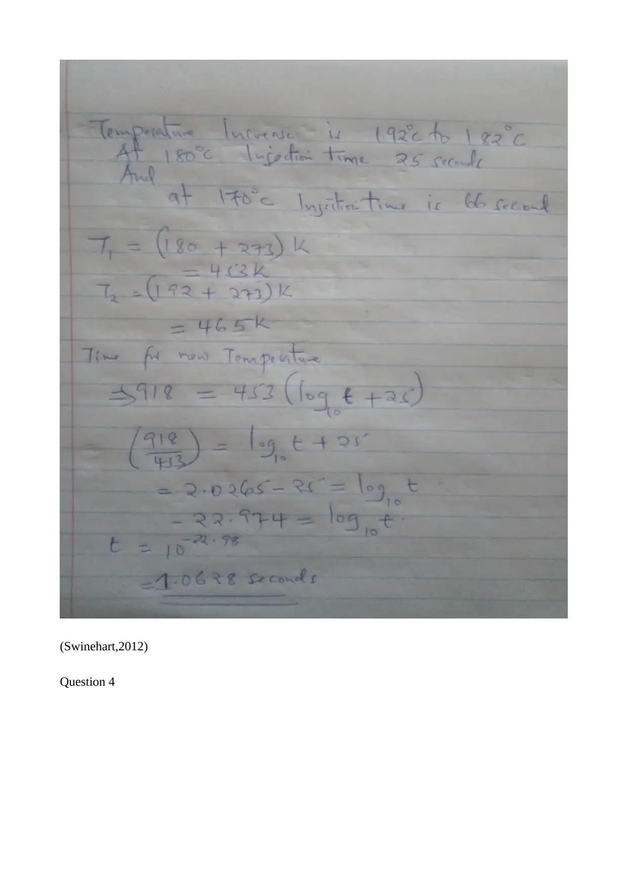
(Swinehart,2012)
Question 4
Question 4
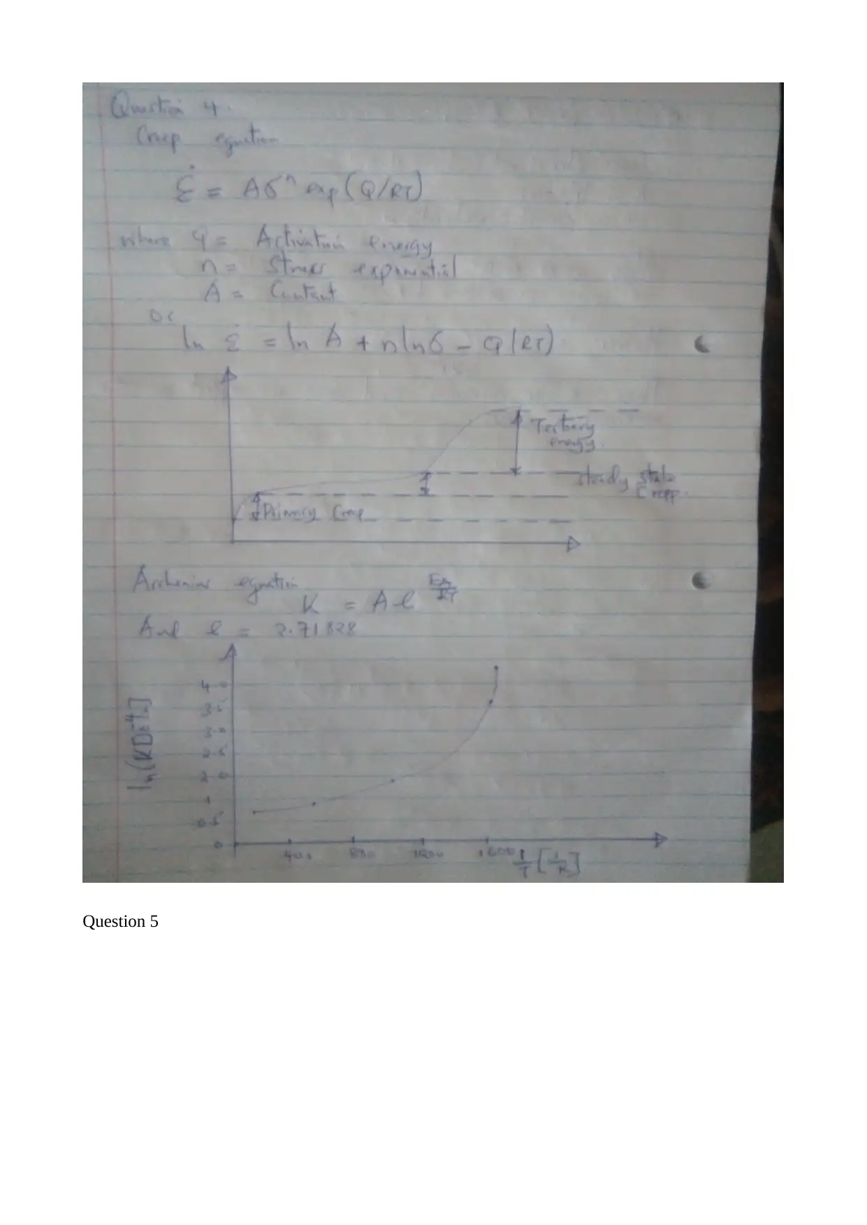
Question 5
⊘ This is a preview!⊘
Do you want full access?
Subscribe today to unlock all pages.

Trusted by 1+ million students worldwide
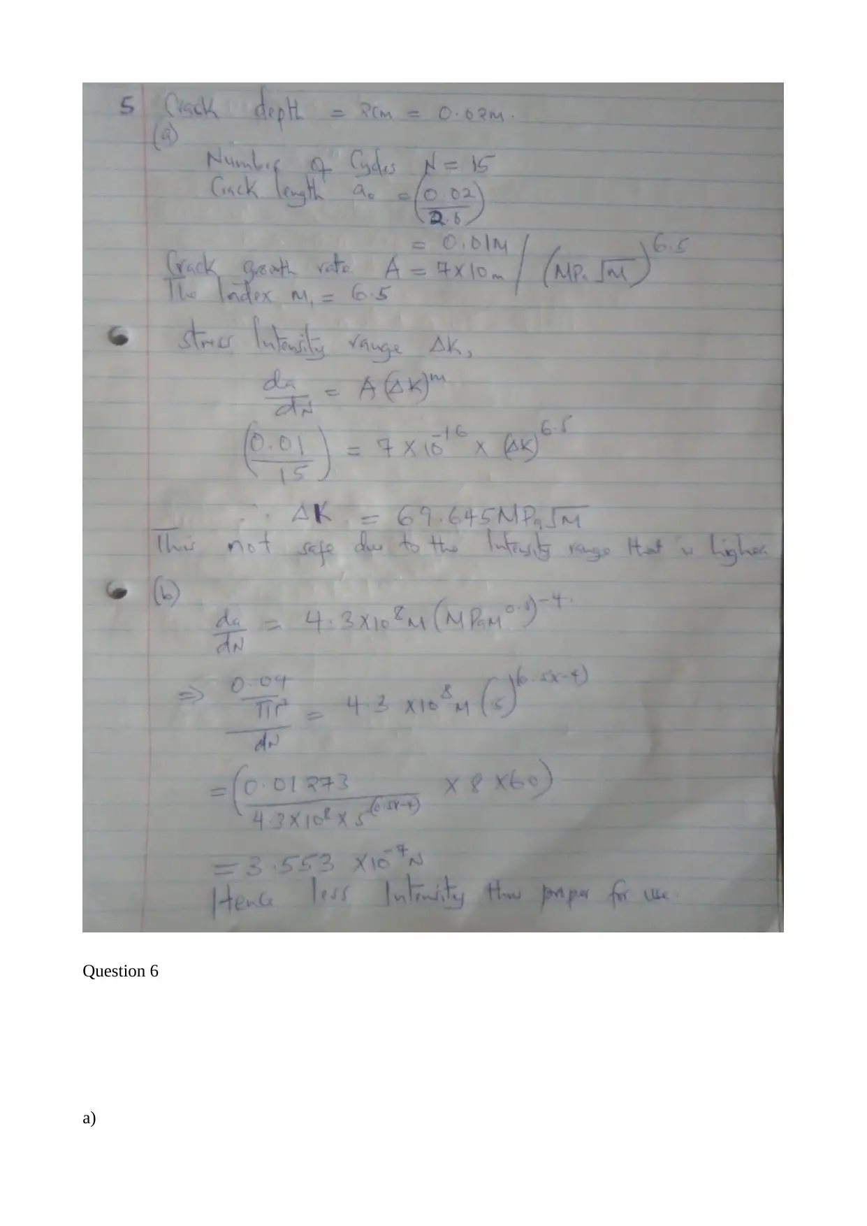
Question 6
a)
a)
Paraphrase This Document
Need a fresh take? Get an instant paraphrase of this document with our AI Paraphraser

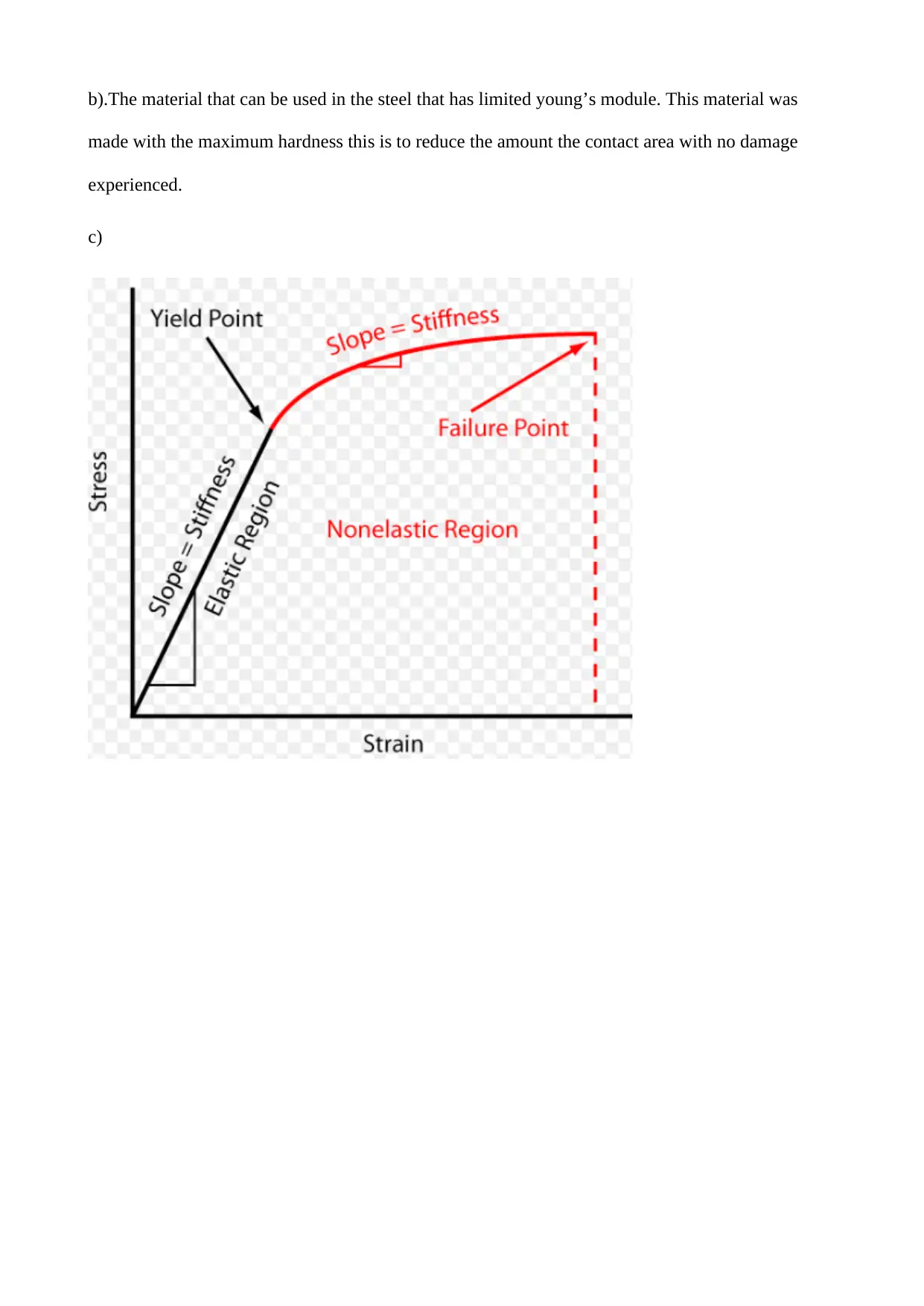
b).The material that can be used in the steel that has limited young’s module. This material was
made with the maximum hardness this is to reduce the amount the contact area with no damage
experienced.
c)
made with the maximum hardness this is to reduce the amount the contact area with no damage
experienced.
c)
⊘ This is a preview!⊘
Do you want full access?
Subscribe today to unlock all pages.

Trusted by 1+ million students worldwide
1 out of 14
Related Documents
Your All-in-One AI-Powered Toolkit for Academic Success.
+13062052269
info@desklib.com
Available 24*7 on WhatsApp / Email
![[object Object]](/_next/static/media/star-bottom.7253800d.svg)
Unlock your academic potential
Copyright © 2020–2026 A2Z Services. All Rights Reserved. Developed and managed by ZUCOL.


