Assessment of Concrete Workability and Sand Quality in Construction
VerifiedAdded on 2020/05/08
|13
|2930
|241
AI Summary
In civil engineering, ensuring high-quality materials is paramount. This report outlines standardized methods for evaluating the workability of concrete through slump testing and assessing the purity of sand by analyzing its silt content. The slump test involves a detailed procedure using specific apparatus to measure concrete's consistency across batches, ensuring uniform quality in construction projects. Meanwhile, the slit test quantifies silt presence in sand, critical for maintaining the durability and strength of structures. Both tests employ precise methodologies, including measurements with calibrated instruments and calculations based on observed values, to ensure material compliance with industry standards.
FIELD TESTING METHODS IN FIELD PAVEMENTS
Objectives
To explain the detail procedure involved in each experiment including their
applications
To demonstrate the requirements of the clients and site conditions
To shed light on the significance of the field testing methods conducted during the
process of the road construction
To renew my experience and knowledge in the field.
Field Tests
Standard Penetration Tests
The standard penetration tests are tests which are usually used to provide information
in regards to the geotechnical engineering soil properties. The tests are inexpensive and
simple compared to the other tests. It is typically used in the approximation of the relative
density of soil including the shear strength parameters.
Description of the Test
The procedure for the standard penetration test constitutes the driving of a thick-
walled sample tube into the ground. Such a tube is pushed into the ground by blows of a
hammer which has a standard weight and falling distance. Further, the tube is driven into the
ground at 150mm. Each of the blows of the hammer for the tube is then recorded for
verification at the sixth minute and eighteenth minute. All the number of blows in the sixth
and eighteenth seconds of the penetration is recorded as the standard penetration test blow
count value. Such a value is referred to as the standard penetration resistance which is the N-
value.
The standard penetration resistance is used to provide a gauge of the density of soils
which are typically difficult to pull up using a borehole sampling technique. Integration of the
Paraphrase This Document
Need a fresh take? Get an instant paraphrase of this document with our AI Paraphraser
standard penetration test with the borehole drilling is usually considered as an improvement
of the comprehensive understanding of a variety of soil types in the underground. The
standard penetration resistance is also used to exhibit the relative density of the subsurface
soil and such information on soil density is applied in empirical geotechnical correlation to
approximate the shear strength properties of a particular soil sample.
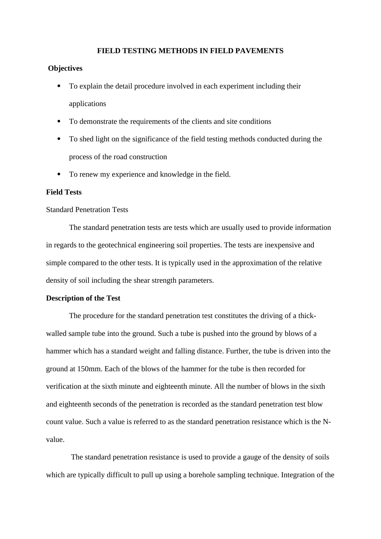
Calibration of the Apparatus
The apparatus is calibrated as follows;
The weight of sand pouring cylinder and sand, W1 (g)
The volume of the calibrating container (Vcm3)
The weight of sand used to fill the conical part on a flat surface, W2.
The weight of sand and sand pouring cylinder after filling the calibrated can,
W3.
The weight of sand needed to fill the calibrated can, Wc= (W1+W2+W3).
Unit weight of sand=Wc/V (g/Cm3)
Measuring Soil Density
of the comprehensive understanding of a variety of soil types in the underground. The
standard penetration resistance is also used to exhibit the relative density of the subsurface
soil and such information on soil density is applied in empirical geotechnical correlation to
approximate the shear strength properties of a particular soil sample.
Calibration of the Apparatus
The apparatus is calibrated as follows;
The weight of sand pouring cylinder and sand, W1 (g)
The volume of the calibrating container (Vcm3)
The weight of sand used to fill the conical part on a flat surface, W2.
The weight of sand and sand pouring cylinder after filling the calibrated can,
W3.
The weight of sand needed to fill the calibrated can, Wc= (W1+W2+W3).
Unit weight of sand=Wc/V (g/Cm3)
Measuring Soil Density
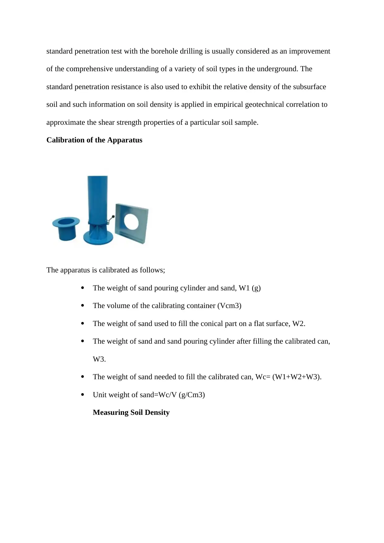
The procedure of Standard Penetration Test
1. Place a tripod on the test hole and arrange the unit
2. Enable the spoon to rest at the bottom of the hole dug.
3. Push the spoon using blows from a hammer which falls 30 inches up to 18
inches to penetrate through the hole.
4. Record all the blows required effect 7 inches of penetration and the first 7
inches of penetration is referred to as the seating drive.
5. Record again the second and third 7 inches of the seating drive and such value
is called the penetration resistance value (N-of the soil)
Precautions During the Test
1. The driving shoe should be replaced using a solid 70-degree cone, and this is
especially when the test is to be conducted in gravely soils.
2. When the tube sample has penetrated less than 27 mm under 60 blows, the
dropping weight should be halted.
3. The sides of the hoe should be supported using drilling mud.
4. Under circumstances in which the soil loosens below the water table, a lot of
care has to be taken into consideration to prevent the entry of water via the
bottom of the bore.
⊘ This is a preview!⊘
Do you want full access?
Subscribe today to unlock all pages.
Trusted by 1+ million students worldwide
Benefits of Standard Penetration Test
It provides accurate and consistent results usually in fine-grained sand unlike in the
clays and coarse sands. The test procedure is significant in regions which are inaccessible by
vehicles since they are used for a preliminary test for the surface conditions.
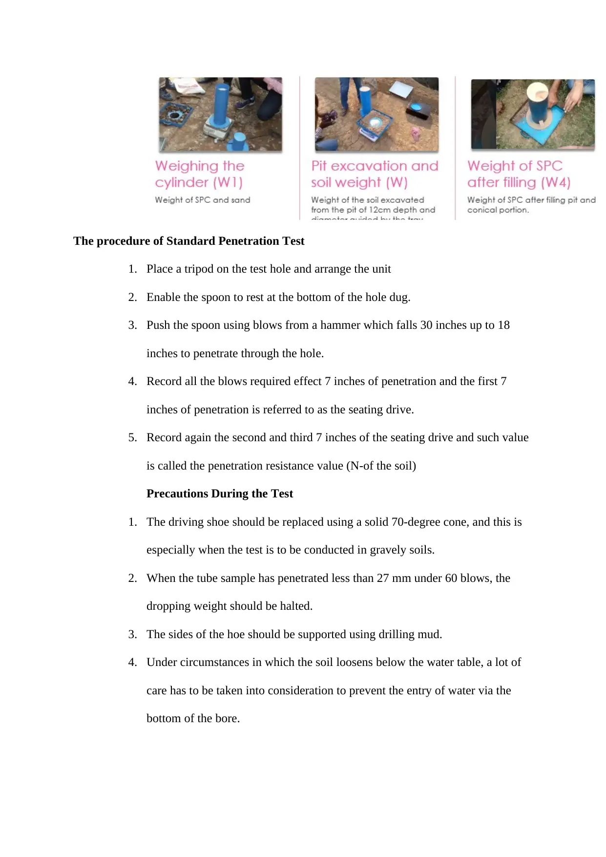
Field Density Test
Sand Replacement Method
In the replacement method, a small pit is usually dug and the weight of soil extracted
is estimated. In the method, sand whose density is identical is placed in the pit. The density
of a particular soil is calculated using the known weight of soil. The sand replacement
method is a technique used in the measurement of field density which involves calibration of
apparatus and measuring of soil density.
Therefore it is a two-stage procedure.
Procedure
Stage 1
1. Estimate the internal dimensions that are height and diameter of the calibrating
can and calculate the internal volume.
2. Put sand in the sand pouring cylinder up to 2cm top clearance. This is to
prevent any spillover during the experiment. Get the weight of the sand.
It provides accurate and consistent results usually in fine-grained sand unlike in the
clays and coarse sands. The test procedure is significant in regions which are inaccessible by
vehicles since they are used for a preliminary test for the surface conditions.
Field Density Test
Sand Replacement Method
In the replacement method, a small pit is usually dug and the weight of soil extracted
is estimated. In the method, sand whose density is identical is placed in the pit. The density
of a particular soil is calculated using the known weight of soil. The sand replacement
method is a technique used in the measurement of field density which involves calibration of
apparatus and measuring of soil density.
Therefore it is a two-stage procedure.
Procedure
Stage 1
1. Estimate the internal dimensions that are height and diameter of the calibrating
can and calculate the internal volume.
2. Put sand in the sand pouring cylinder up to 2cm top clearance. This is to
prevent any spillover during the experiment. Get the weight of the sand.
Paraphrase This Document
Need a fresh take? Get an instant paraphrase of this document with our AI Paraphraser
3. Put the sand pouring cylinder on a glass plate and open the slit through
operations of the valve to enable the sand to flow down. Allow the sand to run
until it fills up the conical portion and then close the slit. Estimate the weight
of the sand used to fill the cone.
4. Put the weight if the sand used to fill the cone in sand pouring cylinder to
enable it to be equal to the weight of the sand in the sand pouring cylinder and
then place the sand pouring cylinder at the top of the calibrated can. Allow the
sand to run until it stops to fill up the conical part of the sand pouring cylinder
and calibrating can. After that close the slit and measure the weight of the
remaining sand in the sand pouring cylinder.
Stage 2: Measurement of Soil Density
Ensure that the ground surface where the soil density is to be calculated is clean and
well leveled.
Put a tray which has a central hole in the soil to be tested.
Dig a pit into the ground via the hole in the plate and the hole is used as a guide to the
diameter of the pit to be placed on the ground.
Gather the amount of soil removed from the ground and measure its weight.
Estimate the amount of moisture of the soil excavated.
Put the sand containing the weight of sand in sand pouring cylinder above the pit, and
this is done to allow the base of the cylinder to cover the pit concentrically.
Unlock the slit of the sand pouring cylinder and let the sand to run freely into the pit.
After the movement has stopped, lock the slit.
Measure the weight of the remaining sand in the sand pouring cylinder.
Precautions
Always remove the tray just prior to the placement of the sand pouring cylinder.
During the test, there should be no vibrations.
There should be no loose material which is left in the pit.
While excavating the pit, an individual should be cautious to avoid digging of a large
pit through levering since a large pit may lead to lower density of the soil being
recorded.
The standard calibrating can have to replace with an internal height which is the same
as the depth of the pit to be dug in the ground, and this is mainly when excavating a
pit with depth above 13cm.
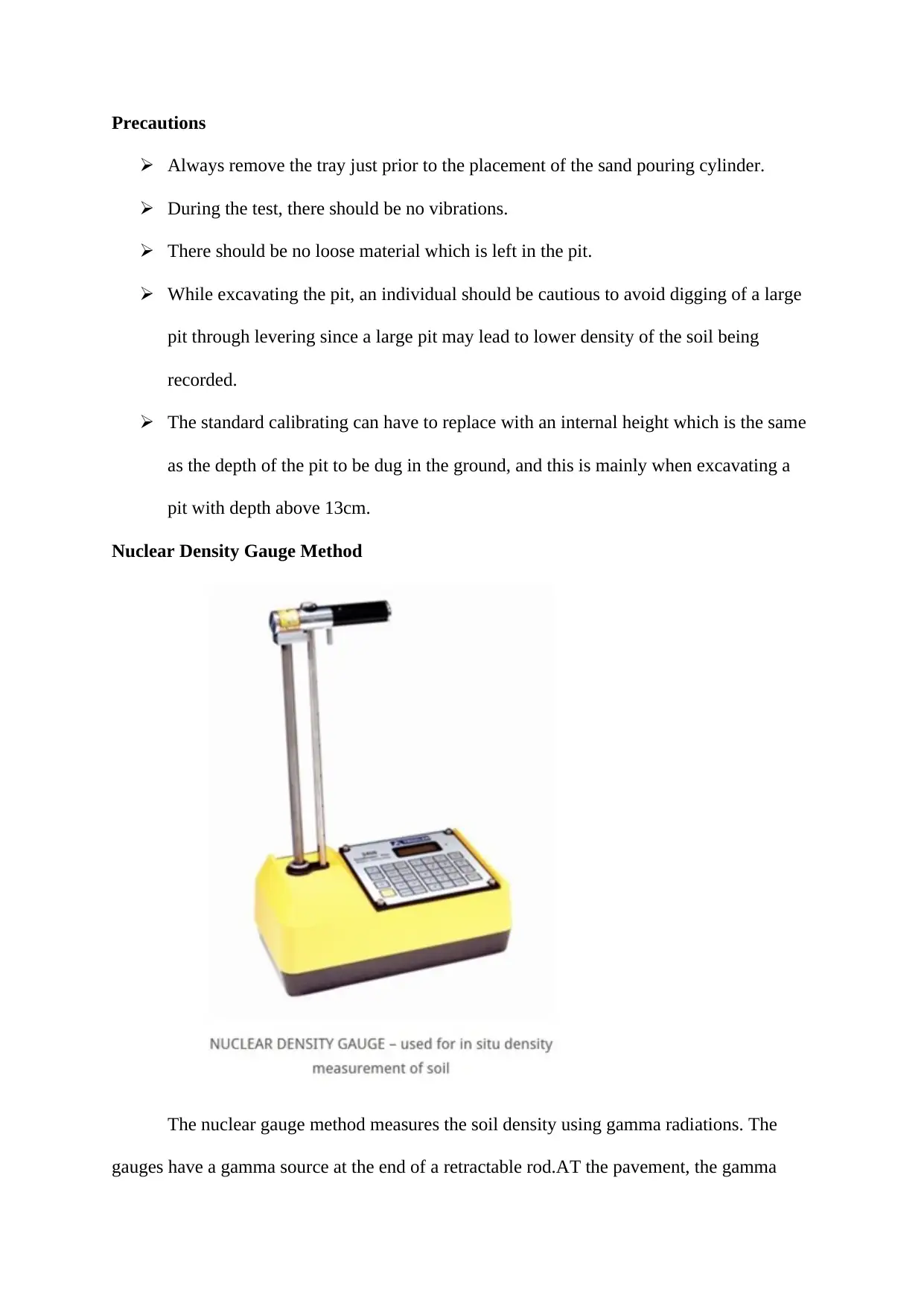
Nuclear Density Gauge Method
The nuclear gauge method measures the soil density using gamma radiations. The
gauges have a gamma source at the end of a retractable rod.AT the pavement, the gamma
Always remove the tray just prior to the placement of the sand pouring cylinder.
During the test, there should be no vibrations.
There should be no loose material which is left in the pit.
While excavating the pit, an individual should be cautious to avoid digging of a large
pit through levering since a large pit may lead to lower density of the soil being
recorded.
The standard calibrating can have to replace with an internal height which is the same
as the depth of the pit to be dug in the ground, and this is mainly when excavating a
pit with depth above 13cm.
Nuclear Density Gauge Method
The nuclear gauge method measures the soil density using gamma radiations. The
gauges have a gamma source at the end of a retractable rod.AT the pavement, the gamma
⊘ This is a preview!⊘
Do you want full access?
Subscribe today to unlock all pages.
Trusted by 1+ million students worldwide

rays produced from a particular source interacts with the electrons, and this is usually through
the process of photoelectric effect, absorption and Compton scattering. The gamma rays are
typically counted using a Geiger Mueller detector. The density of the pavement is then
estimated using the number of gamma rays detected by the detector. There are two typical
modes of the nuclear density gauge used during the determination of the pavement density,
and they include;
Backscatter
Under the backscatter mode, a retractable rod is usually lowered to allow the detector
to detect the gamma rays easily. When the gamma rays interact with the electrons, they lose
energy and thus scattered towards the detector for counting. It is expected that a denser
pavement is an indication of higher detection of the gamma rays by the detector and hence
the pavement density is typically proportional to the counts in the detector.
Direct Transmission
In the direct transmission mode, a retractable rod is lowered in a particular mat via a
pre-drilled hole, and the gamma rays are allowed to interact with the electrons which
eventually lose some amount of energy in the process. During the transmission, the gamma
rays which have been swept away from the detector are not counted. Also, under the above
mode, when the pavement is denser, there is usually a higher probability of the interaction
between the electrons and gamma rays. Additionally, the count of the gamma rays will be
lowered, and hence the pavement density is inversely proportional to the detector count. The
actual density of the pavement is usually related to the gamma count using the calibration
factor.
Advantages of Nuclear Density Gauge
Paraphrase This Document
Need a fresh take? Get an instant paraphrase of this document with our AI Paraphraser
It produces quicker results compared to other modes of measurement of pavement
density. This is in regards to the fact that it only allows for two minute and five
minutes readings, unlike the others which may take several days to read.
The method is also portable since it enables an individual to transport it to another
particular destination easily.
It is non-destructive, and this is primarily when used under backscatter method.
However, when used under the direct mode, just a small penetration is needed to
reach a mat of a diameter of less than 2 inches.
Limitations of Nuclear Density Gauge
The nuclear density gauge usually provides inconsistent results which may as a result of
certain factors such as the poor seating of the gauge, low battery, rock below the surface,
random radiation and poor condition of the surface. The method is also prone to inaccuracy
compare to other techniques which provide precise and precise results.
Precautions
Always do not allow the gauge to become wet
Ensure to clean the paint on a gauge to avoid any false readings.
Only leave the gauge in the filed once it has been attended to by an authorized
individual.
An individual should only transport the nuclear density gauge if you have the
traveling papers which are adequately secured in the vehicle.
Always make sure to charge the batteries of the gauge to avoid inconsistent readings
during the measuring of the pavement density.
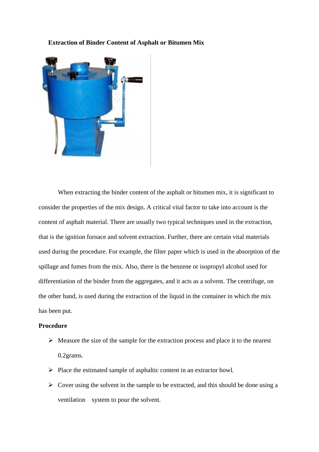
Extraction of Binder Content of Asphalt or Bitumen Mix
When extracting the binder content of the asphalt or bitumen mix, it is significant to
consider the properties of the mix design. A critical vital factor to take into account is the
content of asphalt material. There are usually two typical techniques used in the extraction,
that is the ignition furnace and solvent extraction. Further, there are certain vital materials
used during the procedure. For example, the filter paper which is used in the absorption of the
spillage and fumes from the mix. Also, there is the benzene or isopropyl alcohol used for
differentiation of the binder from the aggregates, and it acts as a solvent. The centrifuge, on
the other hand, is used during the extraction of the liquid in the container in which the mix
has been put.
Procedure
Measure the size of the sample for the extraction process and place it to the nearest
0.2grams.
Place the estimated sample of asphaltic content in an extractor bowl.
Cover using the solvent in the sample to be extracted, and this should be done using a
ventilation system to pour the solvent.
⊘ This is a preview!⊘
Do you want full access?
Subscribe today to unlock all pages.
Trusted by 1+ million students worldwide
Measure the weight of a dry filter paper up to 0.2grams.
Put the filter paper on the extractor bowl
Put into the machine the extractor bowl which has the sample and solvent, lock the
nut to secure the extractor lid and then start the machine.
Halt the centrifuge and gather the liquid discharged in a graduated cylinder.
Add some amount of solvent say 400ml to the solvent and start the machine again.
Stop the machine and collect the discharged liquid. Pour back the liquid and restart
the centrifuge. Weigh the amount of discharged liquid.
Weigh the dried filter.
Remove the original weight of the filter paper from the one weighed after the above
processes.
Place the aggregate in a tared pan and then dry it at a constant temperature of about 94
degrees Celsius and get the weight of the aggregate.
Find the weight of the silica evaporating dish of 250 ml to the nearest 0.02 grams.
Agitate the liquid obtained and then remove 200 ml sample using a pipette.
Evaporate the solvent via gas after pouring the 200 ml in the tared silica dish.
Inflame the residue over a burner for 40 minutes with the aim to ash the bituminous
material and continue with the process until the ashing is finished.
Add ammonium carbonate to the remaining wet ash after it has cooled.
Evaporate the sample to dryness at a very low temperature.
In a room temperature, cool the contents of the dish and find the net weight
Estimate the weight of the residue.
Calculating the Binder Content
The following step is usually involved in the calculation of binder content;
Paraphrase This Document
Need a fresh take? Get an instant paraphrase of this document with our AI Paraphraser
1. Find the weight of sample taken, W1
2. Find the weight of the sample after extraction, W2
3. Get the increased weight of the filter paper, W3 (F2-F1)
4. Get the percentage of the binder in the total mix by, W1-(W1+W3)/W1*100
The result which is obtained is considered as the amount of binder content in the mix. The
method is also referred to as the cold solvent extraction.
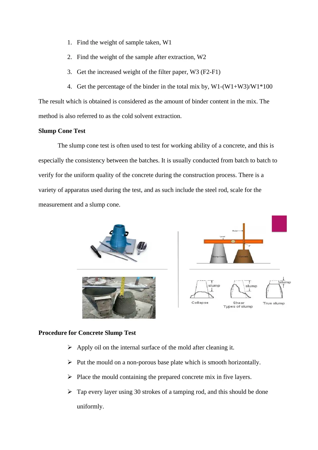
Slump Cone Test
The slump cone test is often used to test for working ability of a concrete, and this is
especially the consistency between the batches. It is usually conducted from batch to batch to
verify for the uniform quality of the concrete during the construction process. There is a
variety of apparatus used during the test, and as such include the steel rod, scale for the
measurement and a slump cone.
Procedure for Concrete Slump Test
Apply oil on the internal surface of the mold after cleaning it.
Put the mould on a non-porous base plate which is smooth horizontally.
Place the mould containing the prepared concrete mix in five layers.
Tap every layer using 30 strokes of a tamping rod, and this should be done
uniformly.
2. Find the weight of the sample after extraction, W2
3. Get the increased weight of the filter paper, W3 (F2-F1)
4. Get the percentage of the binder in the total mix by, W1-(W1+W3)/W1*100
The result which is obtained is considered as the amount of binder content in the mix. The
method is also referred to as the cold solvent extraction.
Slump Cone Test
The slump cone test is often used to test for working ability of a concrete, and this is
especially the consistency between the batches. It is usually conducted from batch to batch to
verify for the uniform quality of the concrete during the construction process. There is a
variety of apparatus used during the test, and as such include the steel rod, scale for the
measurement and a slump cone.
Procedure for Concrete Slump Test
Apply oil on the internal surface of the mold after cleaning it.
Put the mould on a non-porous base plate which is smooth horizontally.
Place the mould containing the prepared concrete mix in five layers.
Tap every layer using 30 strokes of a tamping rod, and this should be done
uniformly.
Eliminate the extra concrete and smoothen the internal surface using a trowel.
Lift the mould slowly from the concrete mix in a vertical position
Estimate the slump by finding the difference between the height of the
specimen tested and that of the mould.
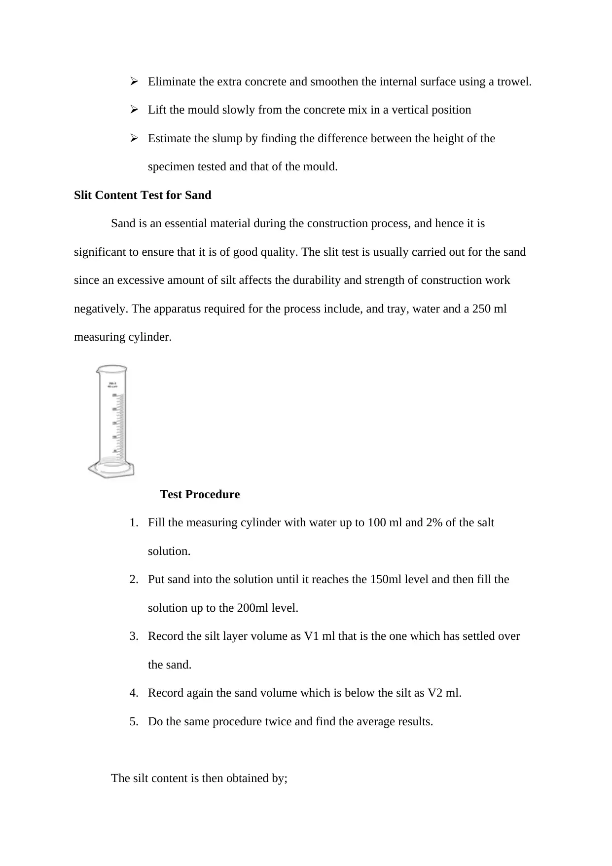
Slit Content Test for Sand
Sand is an essential material during the construction process, and hence it is
significant to ensure that it is of good quality. The slit test is usually carried out for the sand
since an excessive amount of silt affects the durability and strength of construction work
negatively. The apparatus required for the process include, and tray, water and a 250 ml
measuring cylinder.
Test Procedure
1. Fill the measuring cylinder with water up to 100 ml and 2% of the salt
solution.
2. Put sand into the solution until it reaches the 150ml level and then fill the
solution up to the 200ml level.
3. Record the silt layer volume as V1 ml that is the one which has settled over
the sand.
4. Record again the sand volume which is below the silt as V2 ml.
5. Do the same procedure twice and find the average results.
The silt content is then obtained by;
Lift the mould slowly from the concrete mix in a vertical position
Estimate the slump by finding the difference between the height of the
specimen tested and that of the mould.
Slit Content Test for Sand
Sand is an essential material during the construction process, and hence it is
significant to ensure that it is of good quality. The slit test is usually carried out for the sand
since an excessive amount of silt affects the durability and strength of construction work
negatively. The apparatus required for the process include, and tray, water and a 250 ml
measuring cylinder.
Test Procedure
1. Fill the measuring cylinder with water up to 100 ml and 2% of the salt
solution.
2. Put sand into the solution until it reaches the 150ml level and then fill the
solution up to the 200ml level.
3. Record the silt layer volume as V1 ml that is the one which has settled over
the sand.
4. Record again the sand volume which is below the silt as V2 ml.
5. Do the same procedure twice and find the average results.
The silt content is then obtained by;
⊘ This is a preview!⊘
Do you want full access?
Subscribe today to unlock all pages.
Trusted by 1+ million students worldwide
1 out of 13

Your All-in-One AI-Powered Toolkit for Academic Success.
+13062052269
info@desklib.com
Available 24*7 on WhatsApp / Email
![[object Object]](/_next/static/media/star-bottom.7253800d.svg)
Unlock your academic potential
Copyright © 2020–2026 A2Z Services. All Rights Reserved. Developed and managed by ZUCOL.