Report on Modes of Failure and Material Testing in Engineering
VerifiedAdded on 2023/01/18
|10
|1987
|25
Report
AI Summary
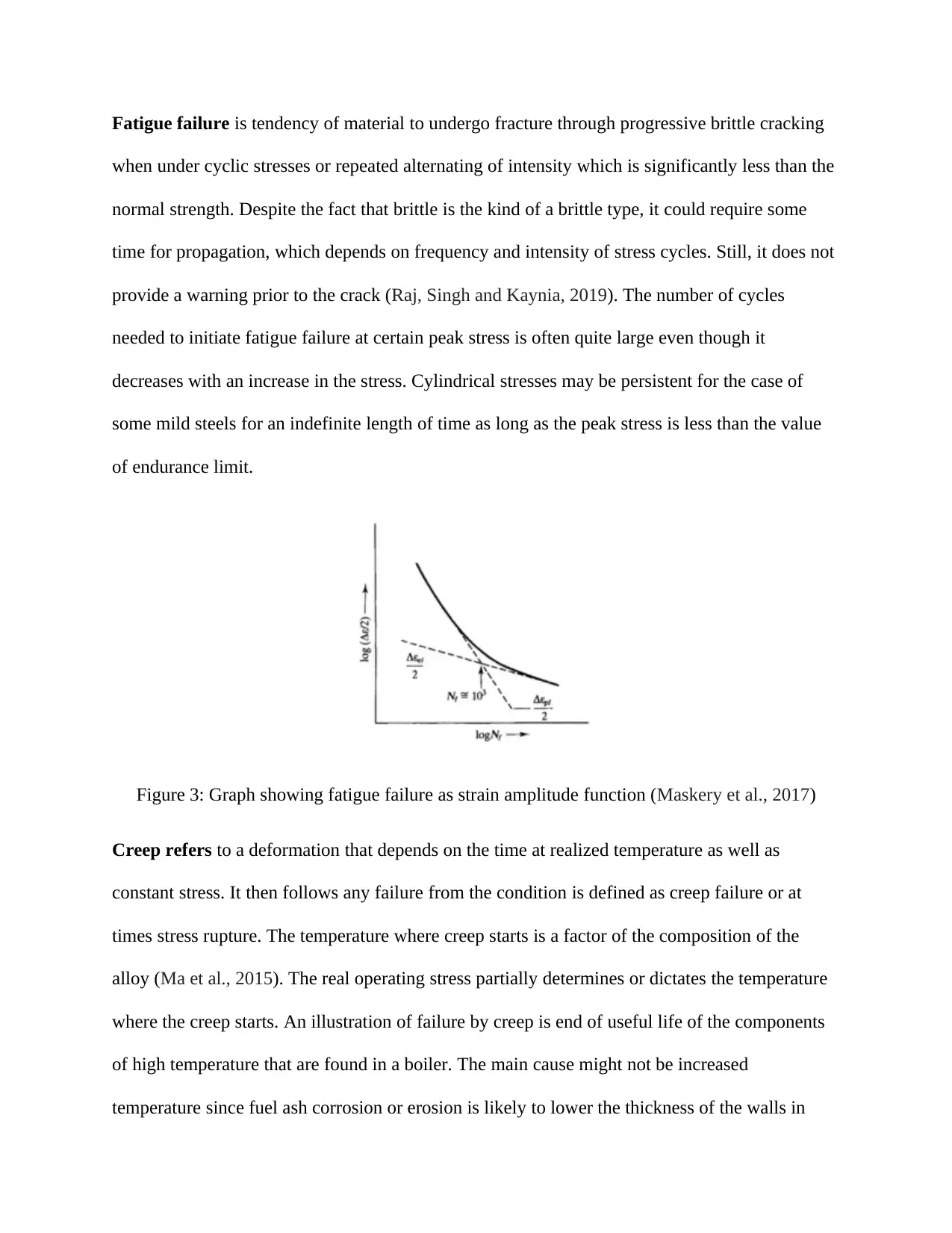
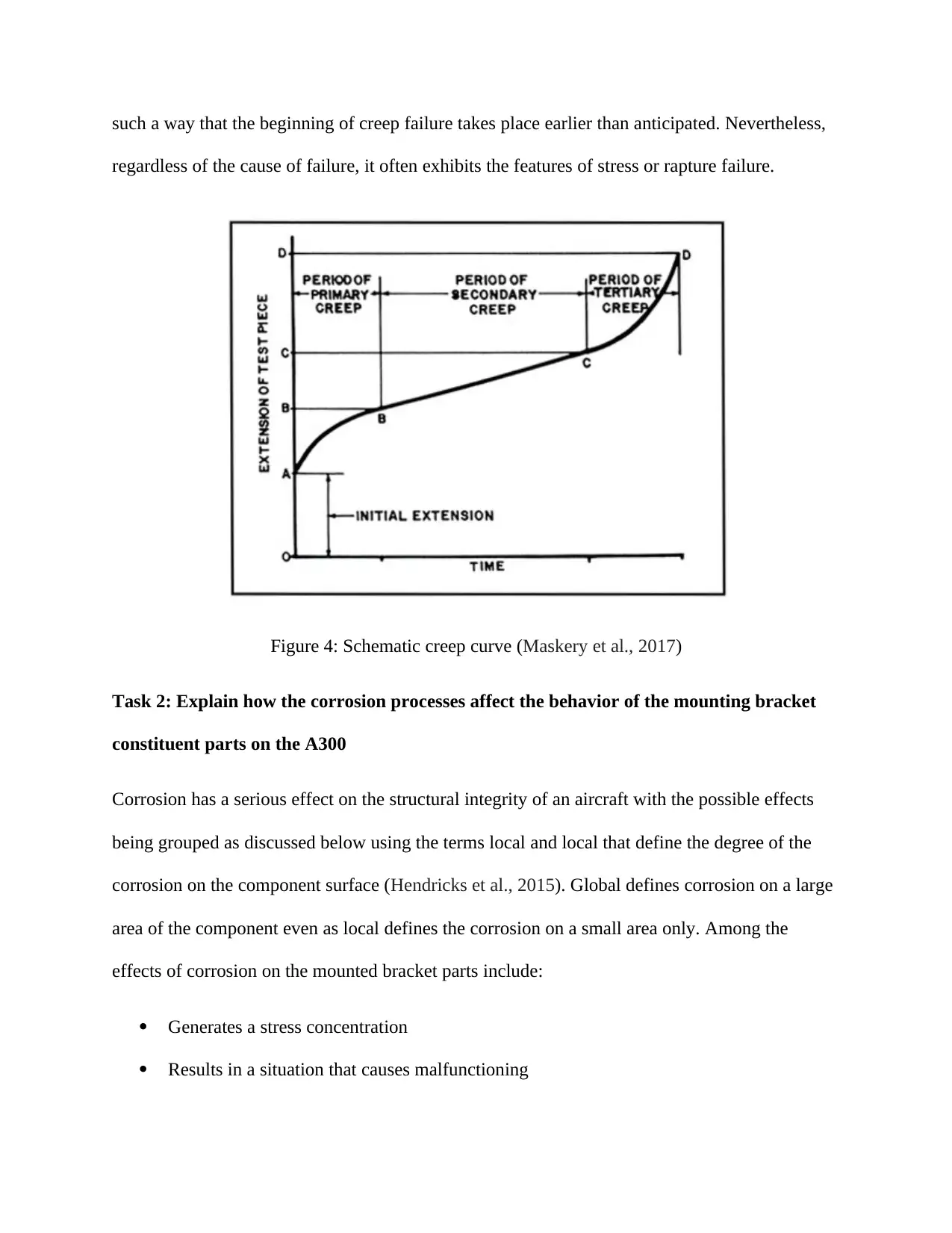
This report provides a detailed analysis of various modes of failure in engineering materials. It begins by defining and differentiating between ductile and brittle fractures, explaining their characteristics, and illustrating their impact on material behavior. The report then explores fatigue failure, discussing its progressive nature and the factors influencing it, followed by an examination of creep, its time-dependent deformation, and the conditions leading to creep failure. The report further investigates the effects of corrosion processes on the behavior of aircraft mounting bracket components, highlighting how corrosion generates stress concentrations, nucleates cracks, and reduces section strength. Finally, the report examines the effects of metal oxidation and thermal shock on engineering materials, detailing the mechanisms and consequences of these degradation processes, including their impact on mechanical properties and structural integrity. The report draws on various sources to support its analysis, providing a comprehensive overview of material failure and degradation.

MODES OF FAILURE AND MATERIAL TESTING
By Name
Course
Instructor
Institution
Location
Date
By Name
Course
Instructor
Institution
Location
Date
Paraphrase This Document
Need a fresh take? Get an instant paraphrase of this document with our AI Paraphraser

Task 1
Ductile fracture refers to a fracture type that is characterized by severe deformation of plastic or
nicking and often taken place before the real fracture. Ductile fracture defines the failure of
materials that are highly ductile and during then the materials tend to pull apart rather than crack.
Massive energy absorption, as well as slow propagation, occurs in ductile fracture prior to the
occurrence of the fracture (Franke, Franke and Harte, 2015). Elaborate plastic deformation or
necking occurs prior to the fracture. The word ductile rupture is a description of the ultimate
failure of materials that are ductile and under tensional loads. Since ductile rupture encompasses
a great extent of plastic deformation, the behavior of the fracture of a propagating cracking
fundamental changes. Some amount of energy from concentrations of stress at the tip of the
crack is given off through plastic deformation prior to crack as it moves along.
The main steps in ductile fracture include formation of void, void coalescence also called
formation of crack propagation of crack as well as failure which usually lead to a cup-and-cone
failure surface shape. The way of propagation of a crack via a material offers insights into the
failure mode. For a ductile fracture, the movement of the crack is low and is often associated
with great amounts of plastic deformation about the crack tip (Maskery et al., 2017). A ductile
crack will often not undergo propagation unless there is application of increased stress and
commonly stop propagating upon removal of the load. The crack may move to a material section
in a ductile material in which the stressed are relatively lower and come to a halt as a result of
blunting impact of plastic deformations which occur at the tip of the crack.
Ductile failure has features that are distinct from the features of brittle failure. Nevertheless, it
may be acknowledge that numerous factures are composed of some of the features of both kinds.
The following are the features of ductile fractures:

The appearance of the ductile fracture is fibrous and dull which is a result of deformation
on the surface of fracture.
There is significant gross permanent or plastic deformation in the area in which the
ductile fracture takes place. In most cases, this could be found only in the region of the
final rupture which might have come with a brittle fracture or fatigue
There is no necessary relationship between the ductile fracture surface and direction of
principal tensile stress as is case with brittle fracture.
Figure 1: Ductile fracture (Maskery et al., 2017)
Brittle fracture refers to the sudden and quite rapid cracking of the equipment when under
stress in which material shows little or no ductility evidence or even plastic degradation prior to
the fracture (Sercombe et al., 2015). Contrary to most of the other tensile members in which the
plasticity of the material strains when under overloaded conditions and tends to be thinner to the
point of the rapture, a surface piece that undergoes fracture does not experience thinking or
⊘ This is a preview!⊘
Do you want full access?
Subscribe today to unlock all pages.

Trusted by 1+ million students worldwide

necking down. Instead this mechanism of damage results in cracking without warning at times
leading to fracture of the equipment into numerous pieces.
Figure 2: Brittle Fracture (Maskery et al., 2017)
Brittle fracture normally results from low temperatures. When the temperature of steel is less
than or at the brittle-to-ductile transition temperature, the material will be susceptible to brittle
force. This combined with critical-sized flow alongside high stress on the flow be it residual or
applied, the material is most likely to experience brittle fracture (Maskery et al., 2017).
Brittle fractures are of two types: intergranular and transgranular fractures. The fractures move
throughout the grain of the material for the case of transgranular fractures. It results in a change
in the direction for grain to another as a result of the various orientation of lattice of the atoms in
every grain following the resistance path. Intergranular fracture takes place when a crack moves
along the boundaries of the grain rather than through the grains (Maskery et al., 2017). The
fracture often takes place when the grain boundary phase is brittle and weak.
Paraphrase This Document
Need a fresh take? Get an instant paraphrase of this document with our AI Paraphraser

Fatigue failure is tendency of material to undergo fracture through progressive brittle cracking
when under cyclic stresses or repeated alternating of intensity which is significantly less than the
normal strength. Despite the fact that brittle is the kind of a brittle type, it could require some
time for propagation, which depends on frequency and intensity of stress cycles. Still, it does not
provide a warning prior to the crack (Raj, Singh and Kaynia, 2019). The number of cycles
needed to initiate fatigue failure at certain peak stress is often quite large even though it
decreases with an increase in the stress. Cylindrical stresses may be persistent for the case of
some mild steels for an indefinite length of time as long as the peak stress is less than the value
of endurance limit.
Figure 3: Graph showing fatigue failure as strain amplitude function (Maskery et al., 2017)
Creep refers to a deformation that depends on the time at realized temperature as well as
constant stress. It then follows any failure from the condition is defined as creep failure or at
times stress rupture. The temperature where creep starts is a factor of the composition of the
alloy (Ma et al., 2015). The real operating stress partially determines or dictates the temperature
where the creep starts. An illustration of failure by creep is end of useful life of the components
of high temperature that are found in a boiler. The main cause might not be increased
temperature since fuel ash corrosion or erosion is likely to lower the thickness of the walls in

such a way that the beginning of creep failure takes place earlier than anticipated. Nevertheless,
regardless of the cause of failure, it often exhibits the features of stress or rapture failure.
Figure 4: Schematic creep curve (Maskery et al., 2017)
Task 2: Explain how the corrosion processes affect the behavior of the mounting bracket
constituent parts on the A300
Corrosion has a serious effect on the structural integrity of an aircraft with the possible effects
being grouped as discussed below using the terms local and local that define the degree of the
corrosion on the component surface (Hendricks et al., 2015). Global defines corrosion on a large
area of the component even as local defines the corrosion on a small area only. Among the
effects of corrosion on the mounted bracket parts include:
Generates a stress concentration
Results in a situation that causes malfunctioning
⊘ This is a preview!⊘
Do you want full access?
Subscribe today to unlock all pages.

Trusted by 1+ million students worldwide

Nucleate cracks
Results in environmentally assisted crack growth under sustained loading and cyclic
conditions
Lowers the section having a concomitant increase in the stress
It generates corrosion debris. This may lead to surface pillowing by different methods
that may to a great extent alter the stress state and structural behavior.
Results in an embrittlement condition in the parts that eventually affect the conduct of the
material (Klein et al., 2011)
Results in a change in the structurally significant item as a result of damage state creation
that is not foreseen in the analysis of the structural damage or strength and fatigue
analysis
Results in a damaged state which is missed in inspection in case the development of the
inspection plan was not done for corrosion or where corrosion was missed.
Produces a damaged state that changes the durability phase of life or even the assessment
of tolerant damage of the parts or even both
Task 4: Effects of various degradation processes on the behavior of engineering materials
Metal oxidation occurs when an ionic chemical reaction takes place on the surface of a metal in
the presence of oxygen. During this reaction, there is a movement of electrons from the metal to
the molecules of oxygen. Negative oxygen ions result are then generated and get into the metal
Paraphrase This Document
Need a fresh take? Get an instant paraphrase of this document with our AI Paraphraser

resulting in the creation of a surface of the oxide. Oxidation is one of the forms of metal
corrosion.
Thermal shock damage takes place in cases where the components are exposed to rapid changes
in the temperature resulting in thermal gradient as well as differential expansions within the
various regions of the component.
Ceramics are known for their high melting points and thus are normally used in situations of high
temperatures. They are normally exposed to rapid changes in temperature. The coefficient of
their thermal expansion is low even though they are stiff as well as brittle and cannot tolerate
high levels of strain that is a result of varying thermal expansion amount in the various parts of
component. The rapid change in the temperature notwithstanding, ceramics alongside other
brittle substances may undergo deformation in case they are exposed to large temperature
gradients.
Ceramics suffer degradation in the strength when they are subjected to server thermal shock as a
result of the damage that results from the shock. Thermal shock also makes ceramic lose their
ductility and reduces the usual LCF life as well as the thermal fatigue life of component. It may
as well result in a brittle fracture that has shorter life compared to normal LCF life.

References
Franke, S., Franke, B. and Harte, A.M., 2015. Failure modes and reinforcement techniques for
timber beams–State of the art. Construction and Building Materials, 97, pp.2-13
Hendricks, C., Williard, N., Mathew, S. and Pecht, M., 2015. Failure modes, mechanisms, and
effects analysis (FMMEA) of lithium-ion batteries. Journal of Power Sources, 297, pp.113-120
Klein, E., Baud, P., Reuschlé, T. and Wong, T.F., 2011. Mechanical behavior and failure mode
of Bentheim sandstone under triaxial compression. Physics and Chemistry of the Earth, Part A:
Solid Earth and Geodesy, 26(1-2), pp.21-25
Ma, Z.S., Xie, Z.C., Wang, Y., Zhang, P.P., Pan, Y., Zhou, Y.C. and Lu, C., 2015. Failure modes
of hollow core-shell structural active materials during the lithiation–delithiation process. Journal
of Power Sources, 290, pp.114-122
Maskery, I., Aboulkhair, N.T., Aremu, A.O., Tuck, C.J. and Ashcroft, I.A., 2017. Compressive
failure modes and energy absorption in additively manufactured double gyroid lattices. Additive
Manufacturing, 16, pp.24-29
Raj, D., Singh, Y. and Kaynia, A.M., 2019. Behavior and Critical Failure Modes of Strip
Foundations on Slopes under Seismic and Structural Loading. International Journal of
Geomechanics, 19(6), p.04019047
Sercombe, T.B., Xu, X., Challis, V.J., Green, R., Yue, S., Zhang, Z. and Lee, P.D., 2015. Failure
modes in high strength and stiffness to weight scaffolds produced by Selective Laser
Melting. Materials & Design, 67, pp.501-508
⊘ This is a preview!⊘
Do you want full access?
Subscribe today to unlock all pages.

Trusted by 1+ million students worldwide

1 out of 10
Related Documents

Your All-in-One AI-Powered Toolkit for Academic Success.
+13062052269
info@desklib.com
Available 24*7 on WhatsApp / Email
Unlock your academic potential
Copyright © 2020–2025 A2Z Services. All Rights Reserved. Developed and managed by ZUCOL.