Materials Science Report: Polymers, Steels, and Ceramics Analysis
VerifiedAdded on 2020/05/28
|11
|3399
|708
Report
AI Summary
This materials science report provides a comprehensive analysis of various topics, including the differences between pearlite, bainite, and martensite in carbon steels, along with their microstructures and properties. It explores Ferrite-Martensite Dual Phase (DP) steels and their advantages in car manufacturing. The report delves into the manufacturing process of carbon fiber reinforced polymer (CFRP) composites, specifically focusing on thermoplastic polymers and chopped carbon fibers, including the critical length calculation and the automated tape laying process. It also discusses the property requirements of hot roller tool steel, the enhancement of material strength through precipitated particles, and the determination of the 18-8 stainless steel point on a ternary phase diagram. Furthermore, the report describes the molecular structure differences between thermoplastics and thermosets, the deformation of polymer structures under tension, and the thermal behavior of crystalline and amorphous structures. Finally, it outlines the factors affecting polymer properties and compares the properties of ceramics to metals, providing typical examples of ceramics.
Question A.1
(a) Discuss the differences between Pearlite, Bainite and Martensite in carbon steels. Sketch the
microstructures and discuss the properties of each phase (e.g. stiffness, strength, toughness,
ductility) with reference to typical applications.
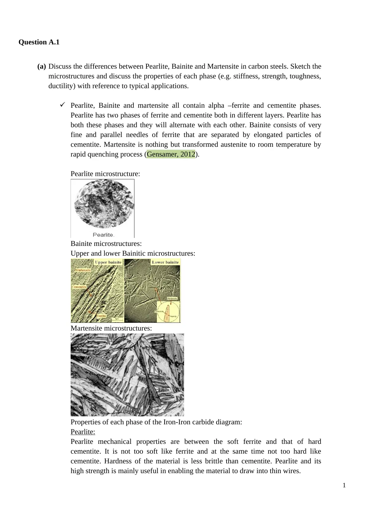
Pearlite, Bainite and martensite all contain alpha –ferrite and cementite phases.
Pearlite has two phases of ferrite and cementite both in different layers. Pearlite has
both these phases and they will alternate with each other. Bainite consists of very
fine and parallel needles of ferrite that are separated by elongated particles of
cementite. Martensite is nothing but transformed austenite to room temperature by
rapid quenching process (Gensamer, 2012).
Pearlite microstructure:
Bainite microstructures:
Upper and lower Bainitic microstructures:
Martensite microstructures:
Properties of each phase of the Iron-Iron carbide diagram:
Pearlite:
Pearlite mechanical properties are between the soft ferrite and that of hard
cementite. It is not too soft like ferrite and at the same time not too hard like
cementite. Hardness of the material is less brittle than cementite. Pearlite and its
high strength is mainly useful in enabling the material to draw into thin wires.
1
(a) Discuss the differences between Pearlite, Bainite and Martensite in carbon steels. Sketch the
microstructures and discuss the properties of each phase (e.g. stiffness, strength, toughness,
ductility) with reference to typical applications.
Pearlite, Bainite and martensite all contain alpha –ferrite and cementite phases.
Pearlite has two phases of ferrite and cementite both in different layers. Pearlite has
both these phases and they will alternate with each other. Bainite consists of very
fine and parallel needles of ferrite that are separated by elongated particles of
cementite. Martensite is nothing but transformed austenite to room temperature by
rapid quenching process (Gensamer, 2012).
Pearlite microstructure:
Bainite microstructures:
Upper and lower Bainitic microstructures:
Martensite microstructures:
Properties of each phase of the Iron-Iron carbide diagram:
Pearlite:
Pearlite mechanical properties are between the soft ferrite and that of hard
cementite. It is not too soft like ferrite and at the same time not too hard like
cementite. Hardness of the material is less brittle than cementite. Pearlite and its
high strength is mainly useful in enabling the material to draw into thin wires.
1
Paraphrase This Document
Need a fresh take? Get an instant paraphrase of this document with our AI Paraphraser
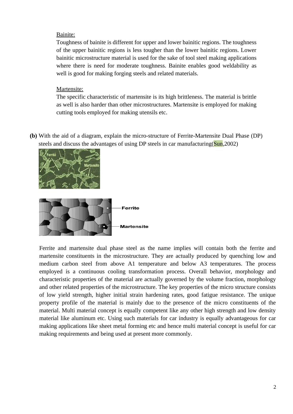
Bainite:
Toughness of bainite is different for upper and lower bainitic regions. The toughness
of the upper bainitic regions is less tougher than the lower bainitic regions. Lower
bainitic microstructure material is used for the sake of tool steel making applications
where there is need for moderate toughness. Bainite enables good weldability as
well is good for making forging steels and related materials.
Martensite:
The specific characteristic of martensite is its high brittleness. The material is brittle
as well is also harder than other microstructures. Martensite is employed for making
cutting tools employed for making utensils etc.
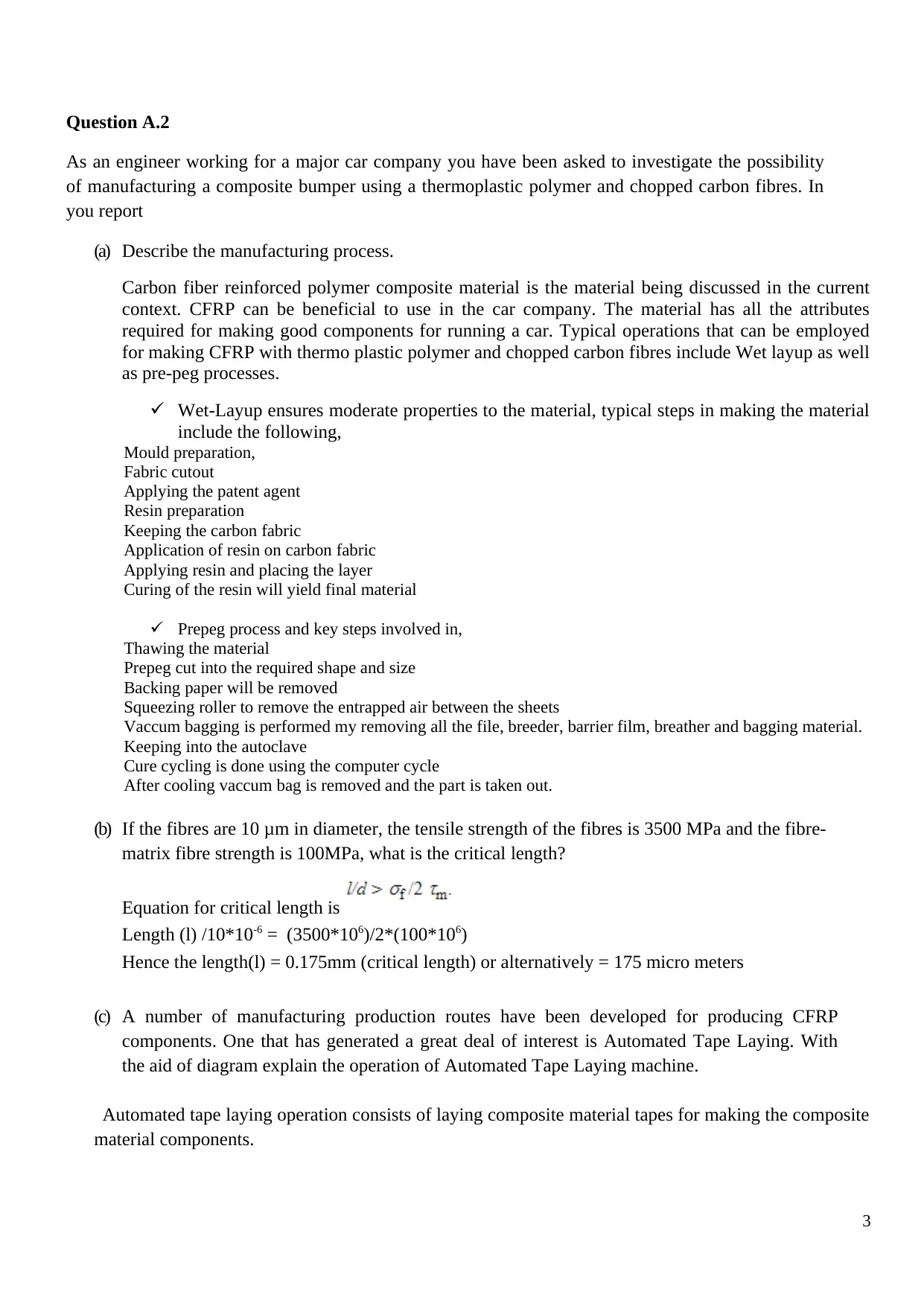
(b) With the aid of a diagram, explain the micro-structure of Ferrite-Martensite Dual Phase (DP)
steels and discuss the advantages of using DP steels in car manufacturing(Sun,2002)
Ferrite and martensite dual phase steel as the name implies will contain both the ferrite and
martensite constituents in the microstructure. They are actually produced by quenching low and
medium carbon steel from above A1 temperature and below A3 temperatures. The process
employed is a continuous cooling transformation process. Overall behavior, morphology and
characteristic properties of the material are actually governed by the volume fraction, morphology
and other related properties of the microstructure. The key properties of the micro structure consists
of low yield strength, higher initial strain hardening rates, good fatigue resistance. The unique
property profile of the material is mainly due to the presence of the micro constituents of the
material. Multi material concept is equally competent like any other high strength and low density
material like aluminum etc. Using such materials for car industry is equally advantageous for car
making applications like sheet metal forming etc and hence multi material concept is useful for car
making requirements and being used at present more commonly.
2
Toughness of bainite is different for upper and lower bainitic regions. The toughness
of the upper bainitic regions is less tougher than the lower bainitic regions. Lower
bainitic microstructure material is used for the sake of tool steel making applications
where there is need for moderate toughness. Bainite enables good weldability as
well is good for making forging steels and related materials.
Martensite:
The specific characteristic of martensite is its high brittleness. The material is brittle
as well is also harder than other microstructures. Martensite is employed for making
cutting tools employed for making utensils etc.
(b) With the aid of a diagram, explain the micro-structure of Ferrite-Martensite Dual Phase (DP)
steels and discuss the advantages of using DP steels in car manufacturing(Sun,2002)
Ferrite and martensite dual phase steel as the name implies will contain both the ferrite and
martensite constituents in the microstructure. They are actually produced by quenching low and
medium carbon steel from above A1 temperature and below A3 temperatures. The process
employed is a continuous cooling transformation process. Overall behavior, morphology and
characteristic properties of the material are actually governed by the volume fraction, morphology
and other related properties of the microstructure. The key properties of the micro structure consists
of low yield strength, higher initial strain hardening rates, good fatigue resistance. The unique
property profile of the material is mainly due to the presence of the micro constituents of the
material. Multi material concept is equally competent like any other high strength and low density
material like aluminum etc. Using such materials for car industry is equally advantageous for car
making applications like sheet metal forming etc and hence multi material concept is useful for car
making requirements and being used at present more commonly.
2
Question A.2
As an engineer working for a major car company you have been asked to investigate the possibility
of manufacturing a composite bumper using a thermoplastic polymer and chopped carbon fibres. In
you report
(a) Describe the manufacturing process.
Carbon fiber reinforced polymer composite material is the material being discussed in the current
context. CFRP can be beneficial to use in the car company. The material has all the attributes
required for making good components for running a car. Typical operations that can be employed
for making CFRP with thermo plastic polymer and chopped carbon fibres include Wet layup as well
as pre-peg processes.
Wet-Layup ensures moderate properties to the material, typical steps in making the material
include the following,
Mould preparation,
Fabric cutout
Applying the patent agent
Resin preparation
Keeping the carbon fabric
Application of resin on carbon fabric
Applying resin and placing the layer
Curing of the resin will yield final material
Prepeg process and key steps involved in,
Thawing the material
Prepeg cut into the required shape and size
Backing paper will be removed
Squeezing roller to remove the entrapped air between the sheets
Vaccum bagging is performed my removing all the file, breeder, barrier film, breather and bagging material.
Keeping into the autoclave
Cure cycling is done using the computer cycle
After cooling vaccum bag is removed and the part is taken out.
(b) If the fibres are 10 μm in diameter, the tensile strength of the fibres is 3500 MPa and the fibre-
matrix fibre strength is 100MPa, what is the critical length?
Equation for critical length is
Length (l) /10*10-6 = (3500*106)/2*(100*106)
Hence the length(l) = 0.175mm (critical length) or alternatively = 175 micro meters
(c) A number of manufacturing production routes have been developed for producing CFRP
components. One that has generated a great deal of interest is Automated Tape Laying. With
the aid of diagram explain the operation of Automated Tape Laying machine.
Automated tape laying operation consists of laying composite material tapes for making the composite
material components.
3
⊘ This is a preview!⊘
Do you want full access?
Subscribe today to unlock all pages.
Trusted by 1+ million students worldwide
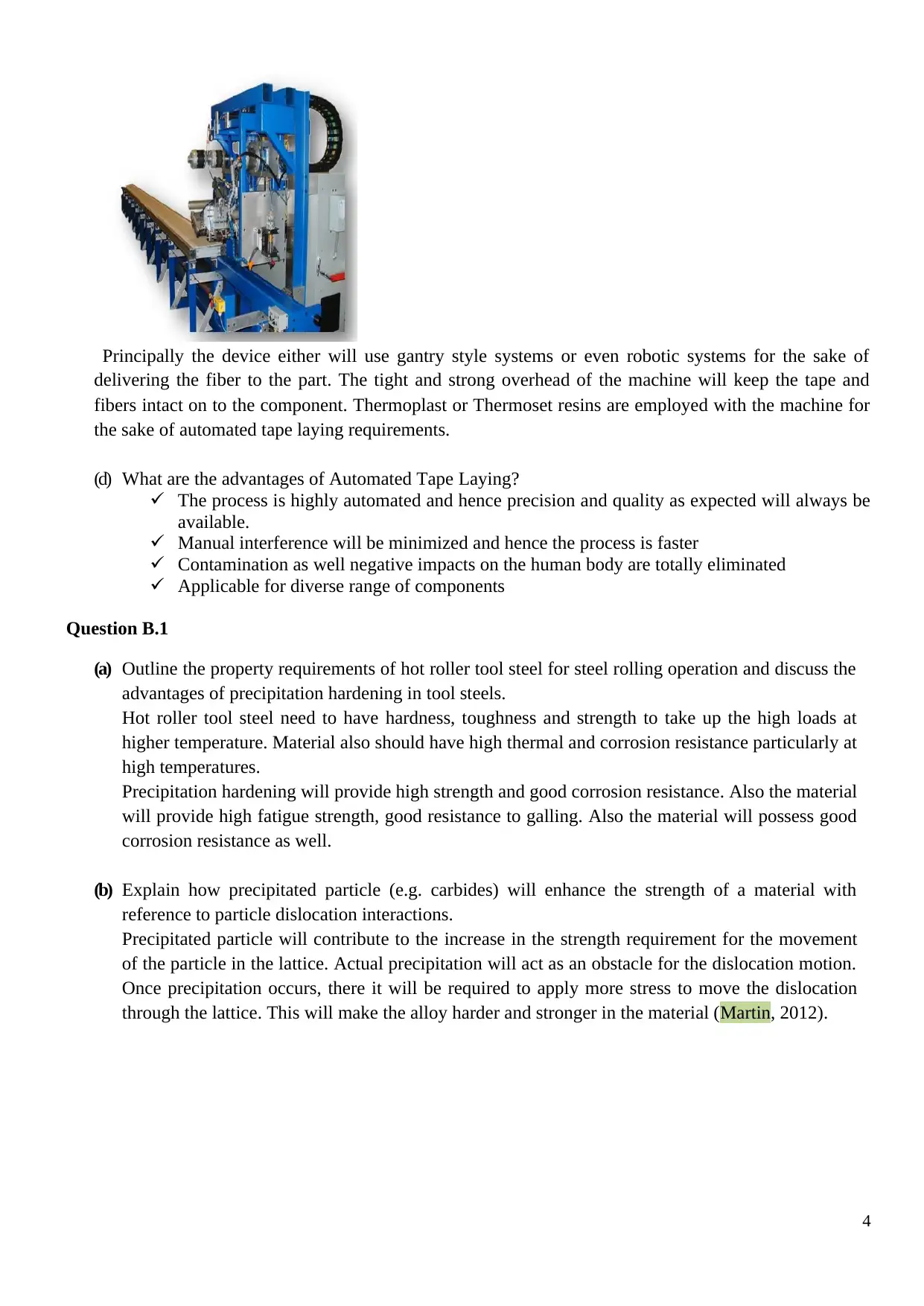
Principally the device either will use gantry style systems or even robotic systems for the sake of
delivering the fiber to the part. The tight and strong overhead of the machine will keep the tape and
fibers intact on to the component. Thermoplast or Thermoset resins are employed with the machine for
the sake of automated tape laying requirements.
(d) What are the advantages of Automated Tape Laying?
The process is highly automated and hence precision and quality as expected will always be
available.
Manual interference will be minimized and hence the process is faster
Contamination as well negative impacts on the human body are totally eliminated
Applicable for diverse range of components
Question B.1
(a) Outline the property requirements of hot roller tool steel for steel rolling operation and discuss the
advantages of precipitation hardening in tool steels.
Hot roller tool steel need to have hardness, toughness and strength to take up the high loads at
higher temperature. Material also should have high thermal and corrosion resistance particularly at
high temperatures.
Precipitation hardening will provide high strength and good corrosion resistance. Also the material
will provide high fatigue strength, good resistance to galling. Also the material will possess good
corrosion resistance as well.
(b) Explain how precipitated particle (e.g. carbides) will enhance the strength of a material with
reference to particle dislocation interactions.
Precipitated particle will contribute to the increase in the strength requirement for the movement
of the particle in the lattice. Actual precipitation will act as an obstacle for the dislocation motion.
Once precipitation occurs, there it will be required to apply more stress to move the dislocation
through the lattice. This will make the alloy harder and stronger in the material (Martin, 2012).
4
Paraphrase This Document
Need a fresh take? Get an instant paraphrase of this document with our AI Paraphraser
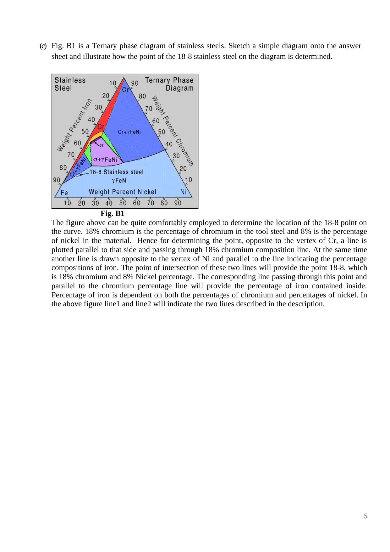
(c) Fig. B1 is a Ternary phase diagram of stainless steels. Sketch a simple diagram onto the answer
sheet and illustrate how the point of the 18-8 stainless steel on the diagram is determined.
Fig. B1
The figure above can be quite comfortably employed to determine the location of the 18-8 point on
the curve. 18% chromium is the percentage of chromium in the tool steel and 8% is the percentage
of nickel in the material. Hence for determining the point, opposite to the vertex of Cr, a line is
plotted parallel to that side and passing through 18% chromium composition line. At the same time
another line is drawn opposite to the vertex of Ni and parallel to the line indicating the percentage
compositions of iron. The point of intersection of these two lines will provide the point 18-8, which
is 18% chromium and 8% Nickel percentage. The corresponding line passing through this point and
parallel to the chromium percentage line will provide the percentage of iron contained inside.
Percentage of iron is dependent on both the percentages of chromium and percentages of nickel. In
the above figure line1 and line2 will indicate the two lines described in the description.
5
Question B.2
(a) With the aid of diagram, describe: (i) the molecule structure difference between thermoplastic and
thermosets, and (ii) the deformation of a linear and cross linked polymer structure under tension
load.
Thermo plastic materials can be remelted again and again for different shapes and component
requirements whereas thermo setting materials are once for all set for the final shapes, once they
are provided with certain shape that is final and that can be remodeled back to its original shape.
Following are the molecular structures of thermoplastic and thermo set materials,
Thermo set polymers: Thermo set polymer molecules are cross linked in all the three dimensions.
Such a cross linking will actually result in very strong structure of the material. Thermo set
plastic materials will actually soften after heating for the first time. When they are allowed to
soften they can take a different shape, As they are set in a permanent and stiff molecular
structure, they will not change further by reheating or even by reshaping like in the case of
thermo plastic materials.
Thermoplastic materials do have linear as well as branched molecular structures. They are quite
flexible at all the ordinary operating temperature ranges. They will become pasty and liquid
masses when they are heated. This is the limitation that will make the thermo plastic materials
applicable only at the room temperature.
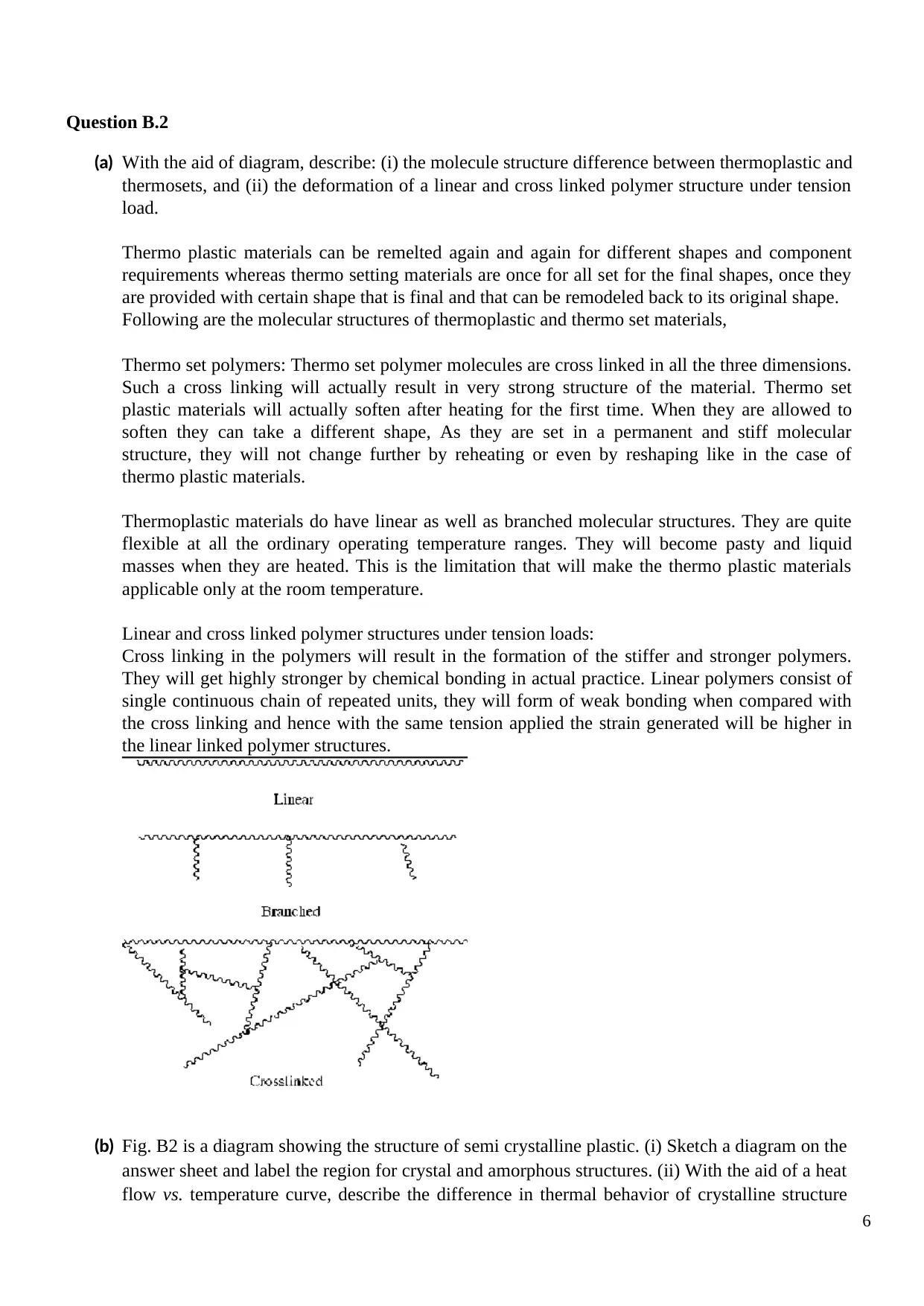
Linear and cross linked polymer structures under tension loads:
Cross linking in the polymers will result in the formation of the stiffer and stronger polymers.
They will get highly stronger by chemical bonding in actual practice. Linear polymers consist of
single continuous chain of repeated units, they will form of weak bonding when compared with
the cross linking and hence with the same tension applied the strain generated will be higher in
the linear linked polymer structures.
(b) Fig. B2 is a diagram showing the structure of semi crystalline plastic. (i) Sketch a diagram on the
answer sheet and label the region for crystal and amorphous structures. (ii) With the aid of a heat
flow vs. temperature curve, describe the difference in thermal behavior of crystalline structure
6
(a) With the aid of diagram, describe: (i) the molecule structure difference between thermoplastic and
thermosets, and (ii) the deformation of a linear and cross linked polymer structure under tension
load.
Thermo plastic materials can be remelted again and again for different shapes and component
requirements whereas thermo setting materials are once for all set for the final shapes, once they
are provided with certain shape that is final and that can be remodeled back to its original shape.
Following are the molecular structures of thermoplastic and thermo set materials,
Thermo set polymers: Thermo set polymer molecules are cross linked in all the three dimensions.
Such a cross linking will actually result in very strong structure of the material. Thermo set
plastic materials will actually soften after heating for the first time. When they are allowed to
soften they can take a different shape, As they are set in a permanent and stiff molecular
structure, they will not change further by reheating or even by reshaping like in the case of
thermo plastic materials.
Thermoplastic materials do have linear as well as branched molecular structures. They are quite
flexible at all the ordinary operating temperature ranges. They will become pasty and liquid
masses when they are heated. This is the limitation that will make the thermo plastic materials
applicable only at the room temperature.
Linear and cross linked polymer structures under tension loads:
Cross linking in the polymers will result in the formation of the stiffer and stronger polymers.
They will get highly stronger by chemical bonding in actual practice. Linear polymers consist of
single continuous chain of repeated units, they will form of weak bonding when compared with
the cross linking and hence with the same tension applied the strain generated will be higher in
the linear linked polymer structures.
(b) Fig. B2 is a diagram showing the structure of semi crystalline plastic. (i) Sketch a diagram on the
answer sheet and label the region for crystal and amorphous structures. (ii) With the aid of a heat
flow vs. temperature curve, describe the difference in thermal behavior of crystalline structure
6
⊘ This is a preview!⊘
Do you want full access?
Subscribe today to unlock all pages.
Trusted by 1+ million students worldwide
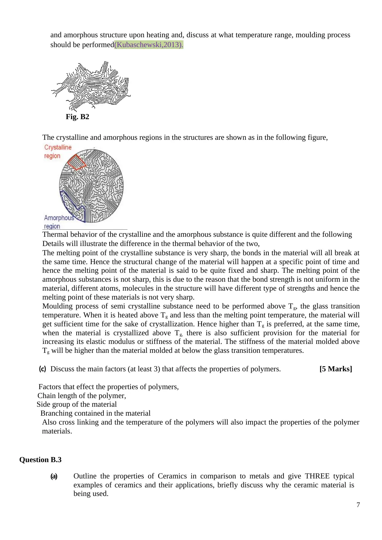
and amorphous structure upon heating and, discuss at what temperature range, moulding process
should be performed(Kubaschewski,2013).
Fig. B2
The crystalline and amorphous regions in the structures are shown as in the following figure,
Thermal behavior of the crystalline and the amorphous substance is quite different and the following
Details will illustrate the difference in the thermal behavior of the two,
The melting point of the crystalline substance is very sharp, the bonds in the material will all break at
the same time. Hence the structural change of the material will happen at a specific point of time and
hence the melting point of the material is said to be quite fixed and sharp. The melting point of the
amorphous substances is not sharp, this is due to the reason that the bond strength is not uniform in the
material, different atoms, molecules in the structure will have different type of strengths and hence the
melting point of these materials is not very sharp.
Moulding process of semi crystalline substance need to be performed above Tg, the glass transition
temperature. When it is heated above Tg and less than the melting point temperature, the material will
get sufficient time for the sake of crystallization. Hence higher than Tg is preferred, at the same time,
when the material is crystallized above Tg, there is also sufficient provision for the material for
increasing its elastic modulus or stiffness of the material. The stiffness of the material molded above
Tg will be higher than the material molded at below the glass transition temperatures.
(c) Discuss the main factors (at least 3) that affects the properties of polymers. [5 Marks]
Factors that effect the properties of polymers,
Chain length of the polymer,
Side group of the material
Branching contained in the material
Also cross linking and the temperature of the polymers will also impact the properties of the polymer
materials.
Question B.3
(a) Outline the properties of Ceramics in comparison to metals and give THREE typical
examples of ceramics and their applications, briefly discuss why the ceramic material is
being used.
7
Paraphrase This Document
Need a fresh take? Get an instant paraphrase of this document with our AI Paraphraser
Ceramics materials do have high thermal resistance when compared to the metals. Also
ceramics materials do possess higher compressive strength when compared with metals.
Also ceramic materials will possess higher brittleness when compared with
metals(Munz,2013).
Typical applications of ceramics include high temperature resistant components like space
craft outer casing elements, applications like tool steels where there will be exposure to
very high operating temperatures, Also ceramic materials are used in the making of
composite materials like cermets, where ceramics will be combined with metals for
making variety of components as well as tool steel materials. Ceramic lining is employed
in automobile cylinders for high temperature resistant applications(Lewis,2013).
Ceramic material is a polymer and unlike metal will not possess corrosion and there is high
thermal resistance and thermal endurance possible. Due to these reasons ceramics are
employed for variety of applications.
(b) Describe the two following toughening mechanisms of ceramics
(i) Transformation Toughening
Transformation toughening process consists of impeding the ceramic structures using stress
induced martensite like materials as second phase for the sake of toughening the structural
ceramic materials. Transformation of such dispersed phase of martensite material will
provide the necessary toughening of the material.
(ii) Micro Cracking
Single phase polycrystalline ceramics are normally subjected to the micro cracking process.
The grains in these materials are anisotropic. In these materials tiny cracks open up on either
way of the main cracks in these materials. Formation of micro cracks in both these sides will
work on to cause two effects, the actual energy required for the formation of the first crack
will be increased. This in turn will limit the tendency of the formation of the crack. Secondly
when the main crack is propagating the secondary cracks formed behind the main crack as
well behind the main crack front will work on to increase the volume of the material, the
increase in the volume of the material will try to close the formation of the main cracks in
the material. This inturn will work to increase the resistance to the propagation of the main
crack.
(c) Outline two typical applications of single crystal materials. In each case, briefly discuss
why the single crystal is being used.
Single crystal lattice will be contained in such single crystal material. The crystal lattice
is unbroken till the edge of the material and will not contain any grain boundaries. As
there are no any grain boundaries the material will offer unique mechanical, optical and
electrical properties.
Some typical applications include applications in optics, electronics and ornaments like
gems. Unique properties of better optical outlook and better physical and mechanical
properties will be make them fit for these applications.
8
Question B.4
The aerospace industry is using Carbon Fiber Reinforced Plastics (CFRP) for an increasing number of its
applications. The reason for this is that CFRP has the material properties that are of great interest to the
aerospace sector, due to its high strength to weight ratio.
(a) With the aid of diagrams explain the tensile stress-strain behavior of CFRP component in a
longitudinal loading and what useful behavior does CFRP have with respect to its
failure mode?
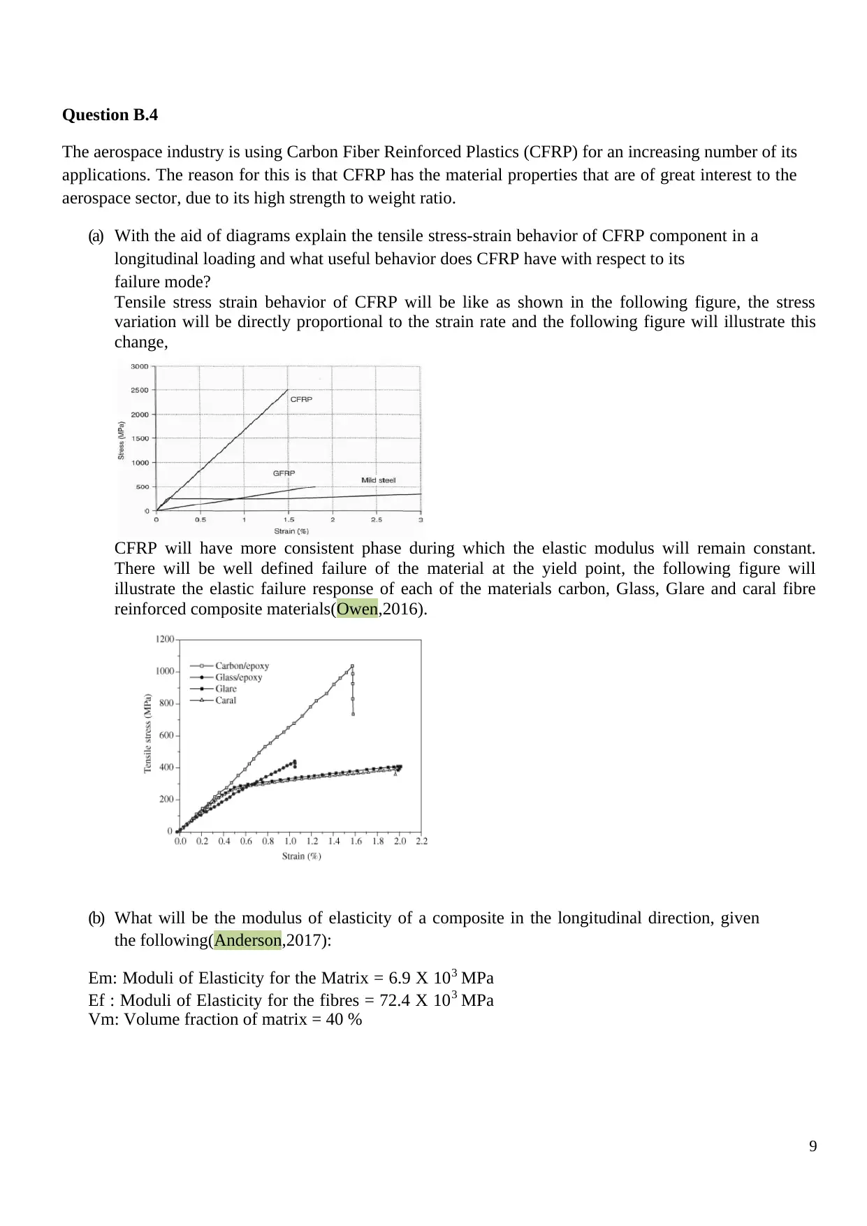
Tensile stress strain behavior of CFRP will be like as shown in the following figure, the stress
variation will be directly proportional to the strain rate and the following figure will illustrate this
change,
CFRP will have more consistent phase during which the elastic modulus will remain constant.
There will be well defined failure of the material at the yield point, the following figure will
illustrate the elastic failure response of each of the materials carbon, Glass, Glare and caral fibre
reinforced composite materials(Owen,2016).
(b) What will be the modulus of elasticity of a composite in the longitudinal direction, given
the following(Anderson,2017):
Em: Moduli of Elasticity for the Matrix = 6.9 X 10³ MPa
Ef : Moduli of Elasticity for the fibres = 72.4 X 10³ MPa
Vm: Volume fraction of matrix = 40 %
9
The aerospace industry is using Carbon Fiber Reinforced Plastics (CFRP) for an increasing number of its
applications. The reason for this is that CFRP has the material properties that are of great interest to the
aerospace sector, due to its high strength to weight ratio.
(a) With the aid of diagrams explain the tensile stress-strain behavior of CFRP component in a
longitudinal loading and what useful behavior does CFRP have with respect to its
failure mode?
Tensile stress strain behavior of CFRP will be like as shown in the following figure, the stress
variation will be directly proportional to the strain rate and the following figure will illustrate this
change,
CFRP will have more consistent phase during which the elastic modulus will remain constant.
There will be well defined failure of the material at the yield point, the following figure will
illustrate the elastic failure response of each of the materials carbon, Glass, Glare and caral fibre
reinforced composite materials(Owen,2016).
(b) What will be the modulus of elasticity of a composite in the longitudinal direction, given
the following(Anderson,2017):
Em: Moduli of Elasticity for the Matrix = 6.9 X 10³ MPa
Ef : Moduli of Elasticity for the fibres = 72.4 X 10³ MPa
Vm: Volume fraction of matrix = 40 %
9
⊘ This is a preview!⊘
Do you want full access?
Subscribe today to unlock all pages.
Trusted by 1+ million students worldwide
Elastic modulus of the composites will be given by,
= Ec = 0.4 * 6.9*103 + 0.6 * 72.4*103 = 46.2 * 103 MPa.
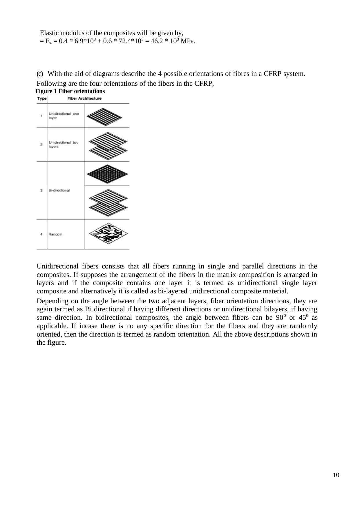
(c) With the aid of diagrams describe the 4 possible orientations of fibres in a CFRP system.
Following are the four orientations of the fibers in the CFRP,
Figure 1 Fiber orientations
Unidirectional fibers consists that all fibers running in single and parallel directions in the
composites. If supposes the arrangement of the fibers in the matrix composition is arranged in
layers and if the composite contains one layer it is termed as unidirectional single layer
composite and alternatively it is called as bi-layered unidirectional composite material.
Depending on the angle between the two adjacent layers, fiber orientation directions, they are
again termed as Bi directional if having different directions or unidirectional bilayers, if having
same direction. In bidirectional composites, the angle between fibers can be 900 or 450 as
applicable. If incase there is no any specific direction for the fibers and they are randomly
oriented, then the direction is termed as random orientation. All the above descriptions shown in
the figure.
10
= Ec = 0.4 * 6.9*103 + 0.6 * 72.4*103 = 46.2 * 103 MPa.
(c) With the aid of diagrams describe the 4 possible orientations of fibres in a CFRP system.
Following are the four orientations of the fibers in the CFRP,
Figure 1 Fiber orientations
Unidirectional fibers consists that all fibers running in single and parallel directions in the
composites. If supposes the arrangement of the fibers in the matrix composition is arranged in
layers and if the composite contains one layer it is termed as unidirectional single layer
composite and alternatively it is called as bi-layered unidirectional composite material.
Depending on the angle between the two adjacent layers, fiber orientation directions, they are
again termed as Bi directional if having different directions or unidirectional bilayers, if having
same direction. In bidirectional composites, the angle between fibers can be 900 or 450 as
applicable. If incase there is no any specific direction for the fibers and they are randomly
oriented, then the direction is termed as random orientation. All the above descriptions shown in
the figure.
10
Paraphrase This Document
Need a fresh take? Get an instant paraphrase of this document with our AI Paraphraser
References:
Anderson, T. L. (2017). Fracture mechanics: fundamentals and applications. CRC press.
Gensamer, M., Pearsall, E. B., Pellini, W. S., & Low, J. R. (2012). The tensile properties of
pearlite, bainite, and spheroidite. Metallography, Microstructure, and Analysis, 1(3-4), 171-189.
Kubaschewski, O. (2013). Iron—Binary phase diagrams. Springer Science & Business Media.
Lewis, M. H. (Ed.). (2013). Glasses and glass-ceramics. Springer Science & Business Media.
Martin, J. W. (2012). Precipitation hardening: theory and applications. Butterworth-
Heinemann.
Munz, D., & Fett, T. (2013). Ceramics: mechanical properties, failure behaviour, materials
selection (Vol. 36). Springer Science & Business Media.
Owen, M. Y. (2016). Fatigue of carbon-fiber-reinforced plastics. Composite materials, 5, 341-
369.
Sun, S., & Pugh, M. (2002). Properties of thermomechanically processed dual-phase steels
containing fibrous martensite. Materials Science and Engineering: A, 335(1), 298-308
11
1 out of 11


Your All-in-One AI-Powered Toolkit for Academic Success.
+13062052269
info@desklib.com
Available 24*7 on WhatsApp / Email
![[object Object]](/_next/static/media/star-bottom.7253800d.svg)
Unlock your academic potential
Copyright © 2020–2026 A2Z Services. All Rights Reserved. Developed and managed by ZUCOL.