MATLAB Assignment: Circuit Analysis, System Response, and Modeling

Verified

Added on  2023/06/14

|17
|2805
|311
Homework Assignment
AI Summary
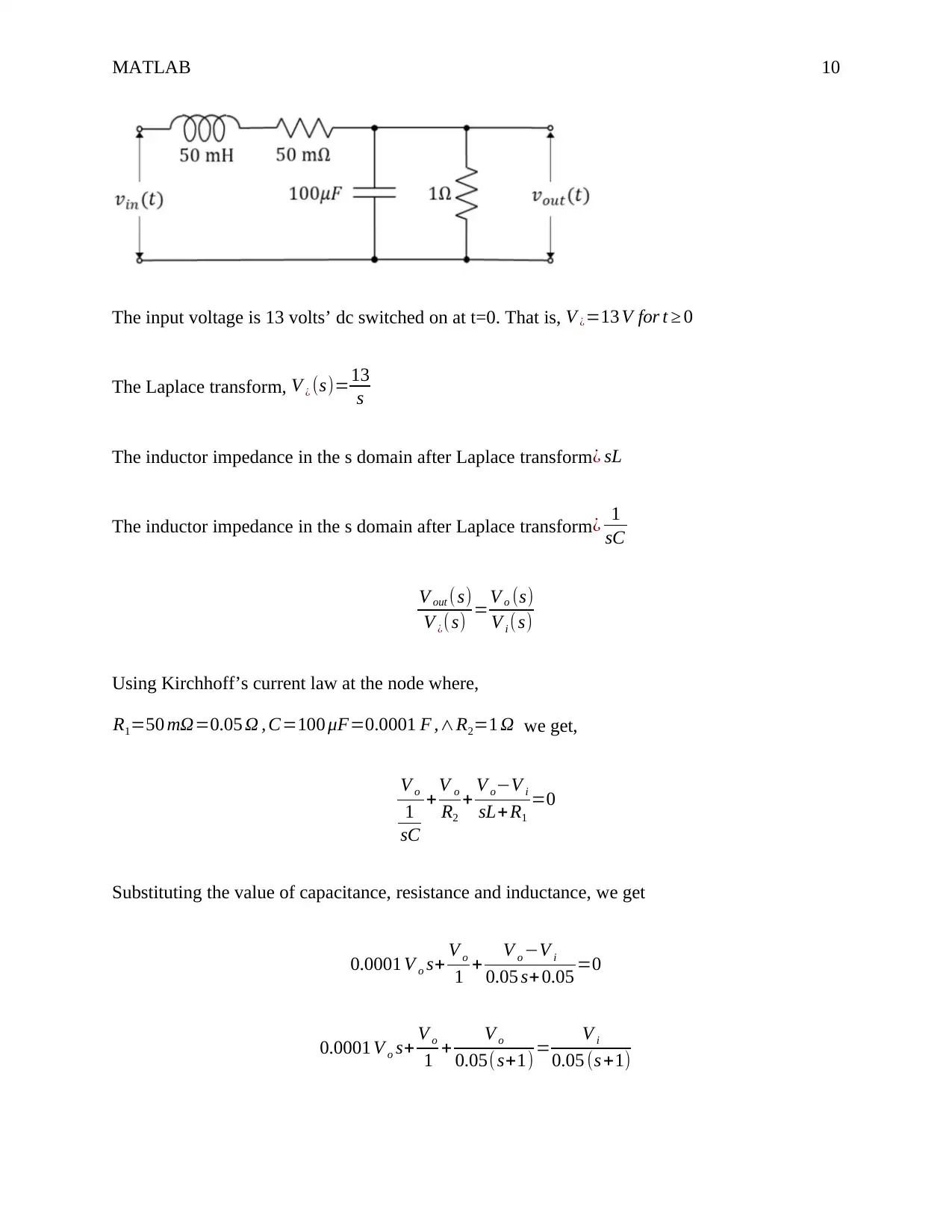
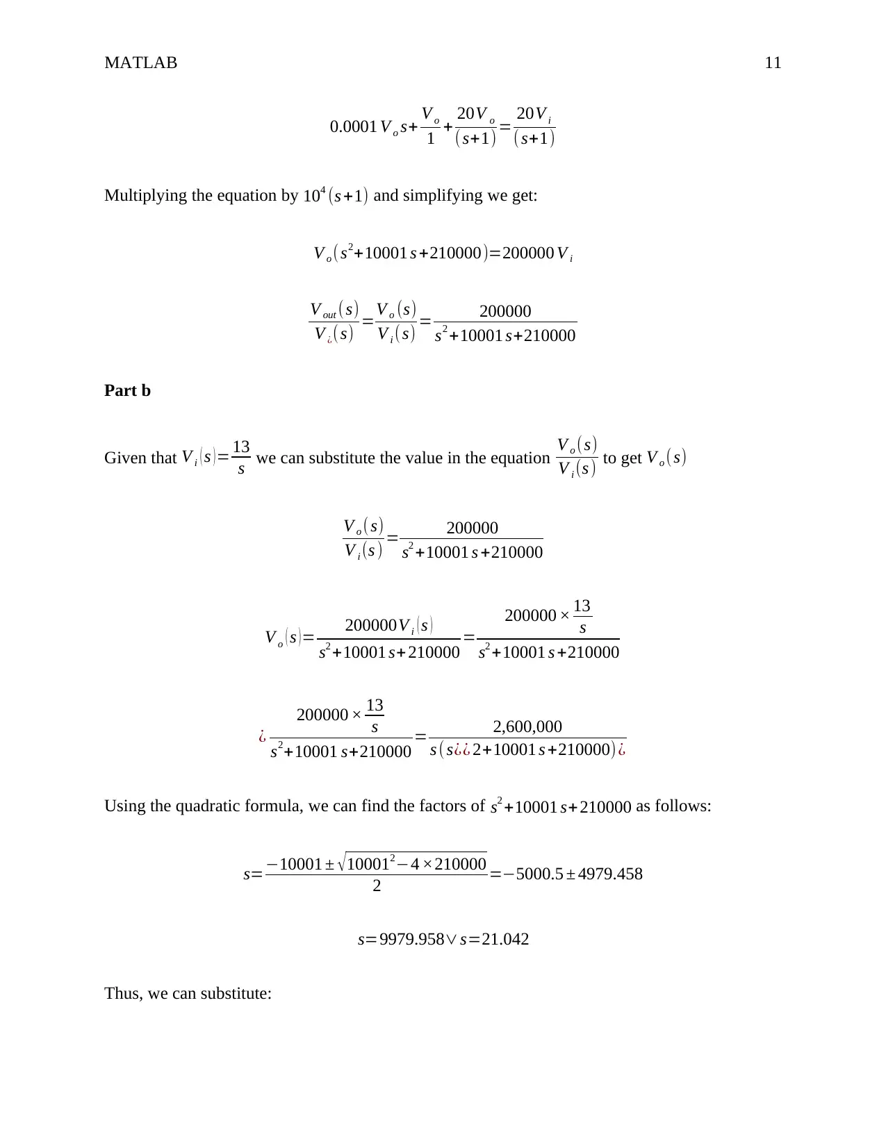
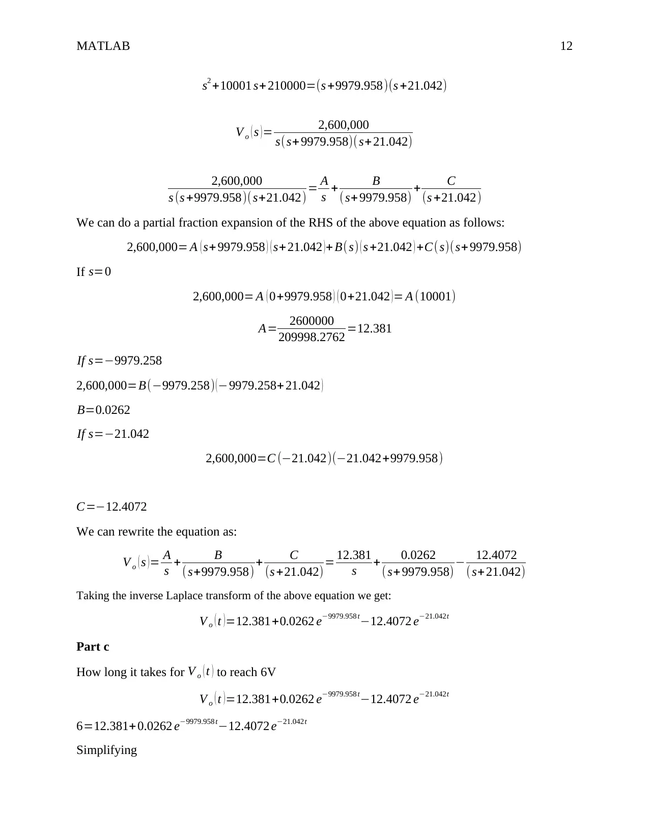
This document presents a solved MATLAB assignment focusing on electrical engineering problems. The assignment includes problems involving Laplace transforms, system modeling, and circuit analysis. Specific topics covered are solving differential equations using Laplace transforms and MATLAB, analyzing transfer functions, and modeling mechanical systems using free body diagrams and transfer functions. The solutions are verified using MATLAB code, and the document includes plots of system responses and Bode plots. The assignment also covers circuit analysis using Kirchhoff's laws and solving for time-domain responses. Desklib provides additional resources such as past papers and solved assignments to aid students in their studies.
Document Page
Running head: MATLAB 1
MATLAB
Name
Institution
tabler-icon-diamond-filled.svg

Paraphrase This Document

Need a fresh take? Get an instant paraphrase of this document with our AI Paraphraser
Document Page
MATLAB 2
MATLAB Assignment
Question 1
Part a
x ' ' +2 x ' + x=5 et + t
Apply Laplace transform on both sides
L { x' ' }+2 L { x' }+L { X }=5 L {et }+L {t }
s2 ˙xsx ( 0 ) ˙x ( 0 ) +2 ( s ˙xx ( 0 ) ) + ˙x= 5
s +1 + 1
s2
But we know that x ( 0 )=0 ˙x ( 0 )=1. Substituting these into the above equation we get:
s2 ˙x1+ s ( s ˙x ) + ˙x= 5
s +1 + 1
s2
˙x ( s2+ s+ 1 )=1+ 5
s +1 + 1
s2
˙x (s+1)2=1+ 5
s+1 + 1
s2
˙x= 1
(s+1)2 + 5
( s+1)3 + 1
s2 ( s+1)2
x=L1
{ 1
(s+ 1)2 }+5 L1
{ 1
(s+ 1)3 }+ L1 { 1
s2 (s +1)2 }
L1
{ 1
(s+ 1)2 }=et t
Document Page
MATLAB 3
5 L1
{ 1
( s+1)3 }=5 et t 2
2
L1
{ 1
s2 ( s+1 )2 }=t+2 et +et t2
x=et t +5 et t2
2 +t +2 et +et t2
Therefore, x=2 et t+2et + 5 et t2
2 +t2
We can prove the answer using the MATLAB code,
syms y(t)
Dy = diff(y);
ode = diff(y,t,2)+2*diff(y,'t',1)+y == 5*exp(-t)+t;
cond1 = y(0) == 0;
cond2 = Dy(0) == 1;
conds = [cond1 cond2];
ySol(t) = dsolve(ode,conds);
ySol = simplify(ySol)
Part b
y +3 ¨y +5 ˙y= x +4 ¨x +6 ˙x +8 x
Apply Laplace transform on both sides (remember all initial conditions are zero)
L { y }+ 3 L { ¨y } +5 L { ˙y }=L{ x }+ 4 L { ¨x }+6 L { ˙x }+8 L {x }
L { y }=s3 Y ( s ) s2 y ( 0 ) s ˙y ( 0 ) ¨y ( 0 ) =s3 Y ( s )
3 L { ¨y }=3 ¿
5 L { ˙y } =5 ¿
Document Page
MATLAB 4
L { x }=s3 X ( s )s2 x ( 0 ) s ˙x ( 0 ) ¨x ( 0 ) =s3 X ( s )
4 L { ¨x }=4 ¿
6 L { ˙x }=6 ¿
8 L { x ) =8 X ( s )
s3 Y ( s ) +3 s2 Y ( s ) +5 sY ( s ) =s3 X ( s ) + 4 s2 X ( s ) + 6 sX ( s ) +8 X ( s )
Simplifying the above equation:
Y ( s ) ( s3+3 s2+5 s ) =X ( s ) ( s3 + 4 s2 +6 s +8)
G ( s ) = Y ( s )
X ( s ) =(s3 +4 s2+ 6 s +8)
( s3 +3 s2 +5 s )
Using the final Value theorem,
lim
n
¿ ¿
Using MATLAB, the impulse response of G ( s ) is shown below.
tabler-icon-diamond-filled.svg

Paraphrase This Document

Need a fresh take? Get an instant paraphrase of this document with our AI Paraphraser
Document Page
MATLAB 5
The MATLAB code used to obtain the above plot is:
sys = tf([1 4 6 8],[1 3 5 0]);
impulse(sys)
We can see that the steady state amplitude equals 1.6. Therefore, we can see that the impulse
response in MATLAB gives the same value as the Final Value theorem.
Question 2
m1=400 kg , m2 =100 kg , DampingCoefficient , B1=1000 Ns /m
Spring constant , k 1=1600 N
m , Spring constant , k2=100000 N
m = 105 N
m
First, we have to draw the free body diagram of the system as shown
Document Page
MATLAB 6
Applying Newton’s second law of motion and writing the expressions of motion of the two
masses:
For mass 1 , m1 ¨Z={K1 ( Z W ) + B1 ( ˙Z ˙W ) }
Finding the Laplace transform and simplifying we get:
( m1 s2+B1 s+k1 ) Z ( s ) =B1 sW ( s ) +k1 W ( s ) equation1
For mass 2 , m2 ¨W =K1 ( ZW ) + B1 ( ˙Z ˙W ) + K 2 ( xW )
Finding the Laplace transform and simplifying we get:
¿
Making W ( s ) the subject of the formula from equation 1, we get
W ( s )= ( m1 s2+ B1 s+k1 ) Z ( s )
B1 s +k1
Document Page
MATLAB 7
Substituting this value in equation 2,
¿
Upon simplification we get:
Z ( s )
R ( s ) = (B¿¿ 1 s+ k1 ) K2
m1 m2 s4 +(m¿¿ 1+m2 )B1 s3 +¿ ¿ ¿ ¿ ¿
Substituting the values in the above equation:
Z ( s )
R ( s ) = (1000 s +1600)105
40000 s4 +500000 s3+(4 ×10⁷ +(500)1600) s2 +108 s+16 ×107
Simplifying
Hence , Z ( s )
R ( s ) = 2500 s +4000
s4 +12.5 s3 +1020 s2+ 6500
Part b
We can use the MATLAB code to plot the transfer function.
H = tf([2500 4000],[1 12.5 1020 0 6500]);
bode(H)
The resulting plot is shown in figure 1 below
tabler-icon-diamond-filled.svg

Paraphrase This Document

Need a fresh take? Get an instant paraphrase of this document with our AI Paraphraser
Document Page
MATLAB 8
Figure 1: Bode Plot of the System Using MATLAB
Given that, r ( t )=3 sin ( 4 πt )
R ( s )=L {3 sin ( 4 πt ) }=3 L {sin ( 4 πt )=3 4 π
s2+16 π2 = 12 π
s2 +16 π 2
Z ( s ) = 2500 s+4000
s4+ 12.5 s3+1020 s2 +6500 R (s )
Z ( s ) = 2500 s+4000
s4+ 12.5 s3+1020 s2 +6500 ( 12 π
s2+16 π2 )
Document Page
MATLAB 9
Part c
When the input is r ( t )=3 sin ( 4 πt ), the peak occurs at t=3 seconds. The peak amplitude at this
time equals -2.7.
The MATLAB code for the above plot is:
H = tf([2500 4000],[1 12.5 1020 0 6500]);
bode(H)
clf
t=0:pi,1000*pi;
u=3*sin(4*pi*t);
lsim(H,u,t)
sys=[1 12.5 1020 0 6500]
roots(sys)
Question 3
Part a
Document Page
MATLAB 10
The input voltage is 13 volts’ dc switched on at t=0. That is, V ¿=13 V for t 0
The Laplace transform, V ¿ (s)=13
s
The inductor impedance in the s domain after Laplace transform ¿ sL
The inductor impedance in the s domain after Laplace transform¿ 1
sC
V out (s)
V ¿(s) =V o (s)
V i (s)
Using Kirchhoff’s current law at the node where,
R1=50 =0.05 Ω , C=100 μF=0.0001 F ,R2=1 Ω we get,
V o
1
sC
+ V o
R2
+ V oV i
sL+ R1
=0
Substituting the value of capacitance, resistance and inductance, we get
0.0001 V o s+ V o
1 + V o V i
0.05 s+ 0.05 =0
0.0001 V o s+ V o
1 + V o
0.05( s+1) = V i
0.05 (s +1)
tabler-icon-diamond-filled.svg

Paraphrase This Document

Need a fresh take? Get an instant paraphrase of this document with our AI Paraphraser
Document Page
MATLAB 11
0.0001 V o s+ V o
1 + 20V o
( s+1)= 20V i
( s+1)
Multiplying the equation by 104 (s +1) and simplifying we get:
V o (s2+10001 s +210000)=200000 V i
V out ( s)
V ¿(s) =V o (s)
V i (s) = 200000
s2 +10001 s+210000
Part b
Given that V i ( s ) = 13
s we can substitute the value in the equation V o (s)
V i (s ) to get V o ( s)
V o ( s)
V i (s ) = 200000
s2 +10001 s +210000
V o ( s )= 200000V i ( s )
s2 +10001 s+ 210000 =
200000 × 13
s
s2 +10001 s +210000
¿
200000 × 13
s
s2+10001 s+210000 = 2,600,000
s ( s¿¿ 2+10001 s +210000) ¿
Using the quadratic formula, we can find the factors of s2 +10001 s+ 210000 as follows:
s=10001 ± 1000124 ×210000
2 =5000.5 ± 4979.458
s=9979.958s=21.042
Thus, we can substitute:
Document Page
MATLAB 12
s2 +10001 s+ 210000=(s +9979.958)(s +21.042)
V o ( s )= 2,600,000
s(s+9979.958)( s+21.042)
2,600,000
s (s +9979.958)( s+21.042)= A
s + B
( s+ 9979.958) + C
(s +21.042)
We can do a partial fraction expansion of the RHS of the above equation as follows:
2,600,000= A ( s+9979.958 ) ( s+21.042 )+ B( s) ( s +21.042 ) +C( s)(s+ 9979.958)
If s=0
2,600,000= A ( 0+9979.958 ) ( 0+21.042 )= A (10001)
A= 2600000
209998.2762 =12.381
If s=9979.258
2,600,000=B(9979.258) ( 9979.258+ 21.042 )
B=0.0262
If s=21.042
2,600,000=C (21.042)(21.042+9979.958)
C=12.4072
We can rewrite the equation as:
V o ( s )= A
s + B
( s+9979.958) + C
(s +21.042)= 12.381
s + 0.0262
( s+ 9979.958) 12.4072
( s+21.042)
Taking the inverse Laplace transform of the above equation we get:
V o ( t ) =12.381+0.0262 e9979.958 t12.4072 e21.042t
Part c
How long it takes for V o ( t ) to reach 6V
V o ( t ) =12.381+0.0262 e9979.958 t12.4072 e21.042t
6=12.381+ 0.0262 e9979.958 t12.4072 e21.042t
Simplifying
chevron_up_icon
1 out of 17
circle_padding
hide_on_mobile
zoom_out_icon
[object Object]