Analysis of Forces and Displacements in Truss Structures Using MATLAB

Verified

Added on  2023/05/28

|5
|1586
|168
Practical Assignment
AI Summary
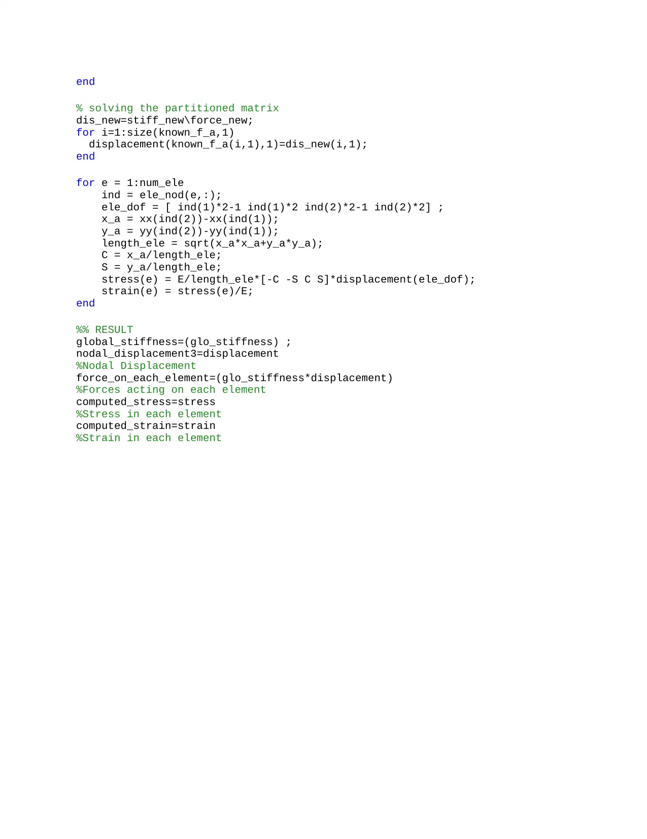
This assignment focuses on analyzing truss structures using the finite element method (FEM) implemented in MATLAB. The primary objective is to determine the forces acting on each joint by applying engineering structure principles and utilizing FEM. The assignment develops a finite element model in MATLAB to compute nodal displacements, axial force, strain, and stress within each member, comparing these results with experimental data. The MATLAB code includes sections for defining material properties (Young's modulus and area), elemental nodes and their coordinates, and the assembly of the global stiffness matrix. Boundary conditions are applied, and the system of equations is solved to find nodal displacements. The assignment also includes a comparative study of nodal displacements for different materials (stainless steel, aluminum, and carbon fiber reinforced plastic), highlighting the impact of material properties on structural behavior. The code computes stress and strain values for each element based on the calculated displacements. This document is available on Desklib, which provides a range of study tools for students.
tabler-icon-diamond-filled.svg

Contribute Materials

Your contribution can guide someone’s learning journey. Share your documents today.
Document Page
Introduction
Truss is a structure that consists of two-force members only, where the members are organized
so that it behaves as a single object. It is assumed to comprise of long, thin members like wood,
steel or concrete joined and bound together in a triangular shape at their endpoints by welding or
gussets. Trusses are either simple, compound or complex, are triangular in shape and bear only
axial force. They are commonly used in bridge construction. Newton's Laws apply to the
structure as a whole, as well as to each node or joint. In order for any node that may be subject to
an external load or force to remain static in space, the following conditions must hold: the sums
of all horizontal forces, all vertical forces, as well as all moments acting about the node equal
zero. Analysis of these conditions at each node yields the magnitude of the forces in each
member of the truss. These may be compression or tension forces. Trusses that are supported at
more than two positions are said to be statically indeterminate, and the application of Newton's
Laws alone is not sufficient to determine the member forces. In order for a truss with pin-
connected members to be stable, it must be entirely composed of triangles. In mathematical
terms, there is necessary condition for stability:
M +R ≥ 2j
M =total number of truss members
j=total number of joints
r=number of reactions (equal to 3 generally)
When m = 2j − 3, the truss is said to be statically determinate, because the (m+3) internal
member forces and support reactions can then be completely determined by 2 j equilibrium
equations.
Some structures are built with more than this minimum number of truss members. Those
structures may survive even when some of the members fail. They are called statically
indeterminate structures, because their member forces depend on the relative stiffness of the
members, in addition to the equilibrium condition described. In a statically indeterminate truss,
static equilibrium alone cannot be used to calculated member force. If we were to try, we would
find that there would be too many “unknowns” and we would not be able to complete the
calculations. Instead we will use a method known as the flexibility method, which uses an idea
know as strain energy.
Objective
The main motive of this experiment is to figure the forces on each joint by the help of
engineering structure by using finite element method.
To develop a finite element model using MATLAB software to calculate the nodal
displacements, axial force, strain and stress in each member and their validation with
experimental results;
tabler-icon-diamond-filled.svg

Secure Best Marks with AI Grader

Need help grading? Try our AI Grader for instant feedback on your assignments.
Document Page
Result
Computed Stress Computed strain
-1.0278 -0.4894
-1.0278 -0.4894
-1.0278 -0.4894
0.5139 0.2447
0.5139 0.2447
1.0278 0.4894
1.0278 0.4894
Nodal Force Nodal displacement
0 0
250 0
0 0.0069
0 -0.0119
0 0
0 -0.0119
0 0.0069
250 0
0 0.0034
500 -0.0218
The values in the experimental force was too different from theoretical values. This can be
happened due to several reasons. As the equipment were not equipped and maintained properly.
There may be some environmental effects on this, as the device is extremely sensible with wind
and noise.
Document Page
There have positive and negative force with tensile and compression at all member. Some
structures are built with more than this minimum number of truss members. Those structures
may survive when some of the members fail or deflection, because their member forces depend
on the relative stiffness of the members. Failure occurs when load effect exceeds the ability of
the structure and can be derived by considering the PDF of ability and load along with their
random distributions. The main goal for safety is to guarantee an ability>load scenario
throughout the design life of structure.
Figure 1: Comparison of nodal displacements between three elements
Figure 1 shows comparative study between Stainless steel, aluminum and carbon fiber reinforced
plastic. It can be clearly seen from the result that steel cannot withstand greater load in
comparison to other two. Aluminum and carbon fiber shows similar behavioral results.
From the comparison of aluminium with carbon fiber we know that material density has a direct
impact on its weight. Carbon fiber composite has a density x 2 times less than aluminium, and
more than 5 times less than steel. Consequently, in a component of the same dimensions,
replacing aluminium with carbon fiber will reduce its weight by 50%. Replacing steel with
carbon fiber will reduce the weight x 5 times.
From the reading of stiffness and strength of a component of the same thickness made from
aluminium, steel and carbon fiber, it can be noted that the component made from carbon fiber of
the same dimensions will be 50% lighter than an aluminium one and more than 5 times lighter
than a steel one.
So from safety point of view, carbon fiber reinforced plastic is safer. But as it does cost very
high, so from cost effectiveness aspect, aluminium should be used.
Code
Clear all;
Clc;
Document Page
%% Inputs
E = 210e9; %Youngs Modulus
A = (pi/4)*(5.98*10^-3)^2; %Area
EA = E*A;
%% Elemental nodes and its coordinates
ele_nod = [ 1 2; 2 3; 3 4; 4 5; 5 1; 5 2; 5 3]; %N
= [starting node,ending node;....]
nod_coor = [ 0 0; 70 121.2436; 210 121.2436; 280 0; 140 0]; %C =
[x_coordinate,y_coordinate;.....]
num_ele = size(ele_nod,1);
num_nod = size(nod_coor,1);
total_nodes = size(nod_coor,1);
xx = nod_coor(:,1);
yy = nod_coor(:,2);
dof = 2*num_nod;
glo_stiffness = zeros(dof);
for e = 1:num_ele
ind = ele_nod(e,:);
ele_dof = [ ind(1)*2-1 ind(1)*2 ind(2)*2-1 ind(2)*2 ] ;
x_a = xx(ind(2))-xx(ind(1));
y_a = yy(ind(2))-yy(ind(1));
length_ele = sqrt(x_a*x_a+y_a*y_a);
C = x_a/length_ele;
S = y_a/length_ele;
ele_stiffness = EA/length_ele * [C*C C*S -C*C -C*S;
C*S S*S -C*S -S*S;
-C*C -C*S C*C C*S;
-C*S -S*S C*S S*S];
glo_stiffness(ele_dof,ele_dof) = glo_stiffness(ele_dof,ele_dof) +
ele_stiffness ;
end
%% Finding Stiffness matrix
displacement=zeros(2*num_nod,1);
force=zeros(2*num_nod,1);
stiffness=zeros(2*num_nod);
%applied loads at DOFs
force(10)=-500;
%Boundary conditions
displacement (1,1)=0.0;
displacement (2,1)=0.0;
displacement (8,1)=0.0;
% % known force array
known_f_a=[3;4;5;6;7;9;10];
for i=1:size(known_f_a,1)
dis_new(i,1)=displacement(known_f_a(i,1),1);
force_new(i,1)=force(known_f_a(i,1),1);
end
for i=1:size(known_f_a,1)
for j=1:size(known_f_a,1)
stiff_new(i,j)=glo_stiffness(known_f_a(i,1),known_f_a(j,1));
end
tabler-icon-diamond-filled.svg

Secure Best Marks with AI Grader

Need help grading? Try our AI Grader for instant feedback on your assignments.
Document Page
end
% solving the partitioned matrix
dis_new=stiff_new\force_new;
for i=1:size(known_f_a,1)
displacement(known_f_a(i,1),1)=dis_new(i,1);
end
for e = 1:num_ele
ind = ele_nod(e,:);
ele_dof = [ ind(1)*2-1 ind(1)*2 ind(2)*2-1 ind(2)*2] ;
x_a = xx(ind(2))-xx(ind(1));
y_a = yy(ind(2))-yy(ind(1));
length_ele = sqrt(x_a*x_a+y_a*y_a);
C = x_a/length_ele;
S = y_a/length_ele;
stress(e) = E/length_ele*[-C -S C S]*displacement(ele_dof);
strain(e) = stress(e)/E;
end
%% RESULT
global_stiffness=(glo_stiffness) ;
nodal_displacement3=displacement
%Nodal Displacement
force_on_each_element=(glo_stiffness*displacement)
%Forces acting on each element
computed_stress=stress
%Stress in each element
computed_strain=strain
%Strain in each element
chevron_up_icon
1 out of 5
circle_padding
hide_on_mobile
zoom_out_icon
logo.png

Your All-in-One AI-Powered Toolkit for Academic Success.

Available 24*7 on WhatsApp / Email

[object Object]